Downloaded 31 times


![70 Water Leak Alarm/Detector 61F-WLA/-GPN-V50
Water Leak Alarm/Detector
61F-WLA/-GPN-V50
• Eliminate Problems Caused from Water Leakage
• 0 to 50 kW variable operating resistance to detect virtually any
liquid.
• Two types available: Water Leak Alarm (61F-WLA) and plug-in
Water Leak Detector (61F-GPN-V50).
• 24 VAC interelectrode voltage causes no electrolytic corrosion.
• Suggested applications include computer room, power plant,
factory, library, warehouse, and basement use.
• Conforms to EMC/IEC Standards (61F-GPN-V50).
• Approved by UL/CSA (61F-GPN-V50)
Ordering Information
When ordering, to complete the part number, be sure to specify the
desired operating voltage.
Specifications
■ Ratings/Characteristics
Note: 1. For detecting leakage of water with high resistivity, use 61F-UHS or 61F-HSL ultra high-sensitivity models. (Refer to page 34.)
2. The Detector may not operate around the setting value of “0.” Adjust the sensitivity depending on the actual application.
Water Leak Alarm 61F-WLA
Water Leak Detector 61F-GPN-V50
Example: 61F-WLA [120/240 VAC]
Desired supply voltage
Item Water Leak Alarm Water Leak Detector
Model 61F-WLA 61F-GPN-V50
Supply voltage 100/200, 110/220, 120/240 VAC 100, 110, 120, 200, 220, 240 VAC
Interelectrode voltage 24 VAC
Operating current 3 mA (AC) max.
Power consumption 8.0 VA max. 3.2 VA max.
Sensitivity Variable (0 to 50 kW)
Error (against the scale) Scale 0: 10 kW
Scale 50: –10 kW(see note 2)
Scale 0: 10 kW
Scale 50: –10 kW(see note 2)
Contact ratings 3 A 250 VAC, SPDT cosf=1
1 A 250 VAC, SPDT cosf=0.4
3 A 250 VAC, DPDT cosf=1
1 A 250 VAC, DPDT cosf=0.4
Indicator Provided (Power and Leak indicators) Provided (Operation indicator)
Alarm buzzer Provided Not provided
Test switch Provided Not provided
Ambient temperature –10•C to 55•C
www.eusens.com
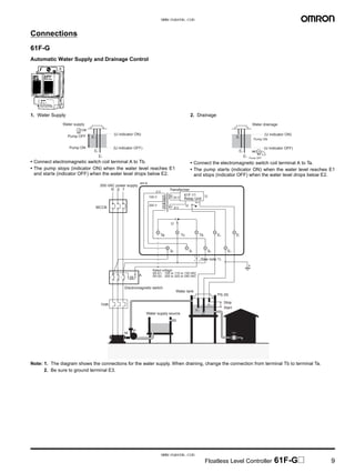
www.eusens.com](https://image.slidesharecdn.com/61ffloatlesslevelcontrollerdatasheet-160830144344/85/61F-Floatless-Level-Controller-Datasheet-70-320.jpg)


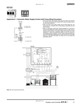
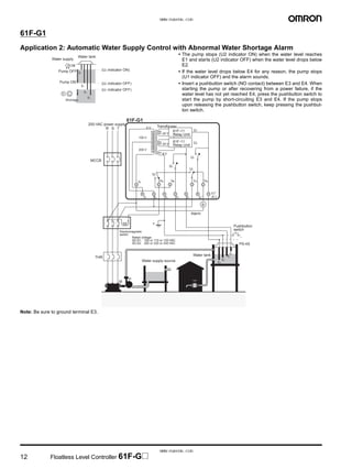
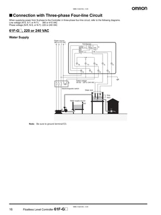
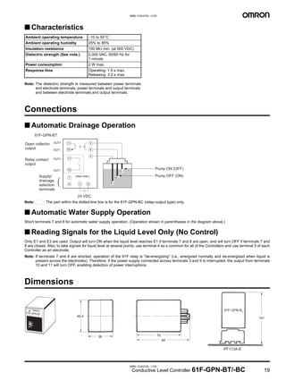
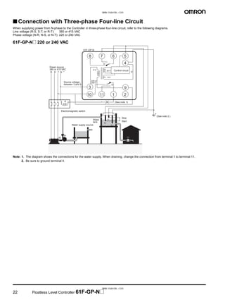
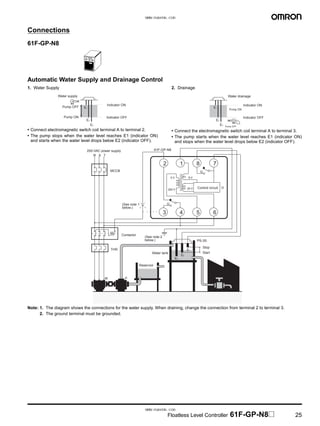
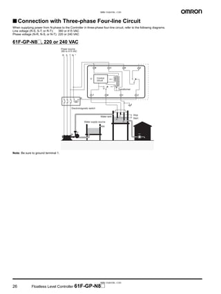
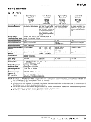
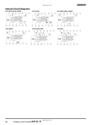
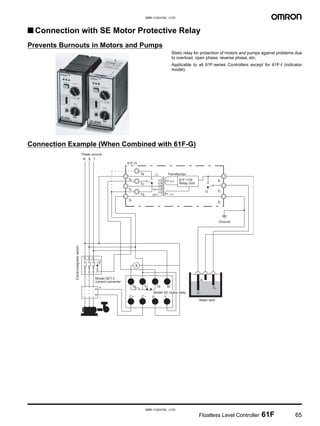
The document summarizes the operating principles and applications of the 61F Floatless Level Controller. It can automatically control liquid levels without a float, using electrodes to electrically detect the liquid level. Models are available for general use or high temperatures. It has applications in water supply, drainage control, and leakage detection.


