1. RCS2CR ROBO Cylinder
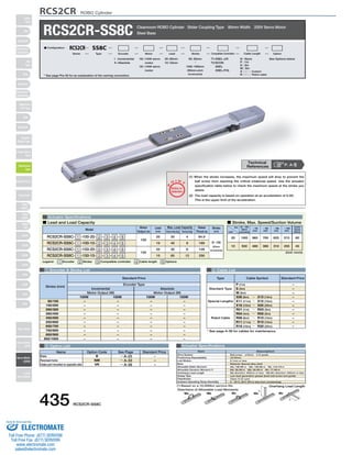
RCS2CR-SS8C Cleanroom ROBO Cylinder Slider Coupling Type 80mm Width 200V Servo Motor
O I N
P
T
Notes on
Selection
T1:XSEL-J/K
T2:SCON
SSEL
XSEL-P/Q
(1) When the stroke increases, the maximum speed will drop to prevent the
ball screw from reaching the critical rotational speed. Use the actuator
specification table below to check the maximum speed at the stroke you
desire.
(2) The load capacity is based on operation at an acceleration of 0.3G.
This is the upper limit of the acceleration.
100 : 100W servo
motor
150 : 150W servo
motor
I : Incremental
A : Absolute
■ Lead and Load Capacity ■ Stroke, Max. Speed/Suction Volume
Model Stroke
Type Cable Symbol Standard Price
P (1m)
S (3m)
M (5m)
X06 (6m) ~ X10 (10m)
X11 (11m) ~ X15 (15m)
X16 (16m) ~ X20 (20m)
R01 (1m) ~ R03 (3m)
R04 (4m) ~ R05 (5m)
R06 (6m) ~ R10 (10m)
R11 (11m) ~ R15 (15m)
R16 (16m) ~ R20 (20m)
L
Overhang Load Length
L
Standard Type
Special Lengths
Robot Cable
Max. Load Capacity Rated
6
128
Drive System
Positioning Repeatability
Lost Motion
Base
Allowable Static Moment
Allowable Dynamic Moment (*)
Overhang Load Length
Grease Type
Cleanliness
Ambient Operating Temp./Humidity
(*) Based on a 10,000km service life.
Directions of Allowable Load Moments
Ma Mb Mc Ma Mc
–
–
–
–
–
–
–
–
–
–
–
* See page A-39 for cables for maintenance.
SA4D : Aluminum
base
SS4D : Steel base
Steel Base
Actuator Specifications
20
30
Legend: 1 Encoder 2 Stroke 3 Compatible controller 4 Cable length 5 Options
1 Encoder & Stroke List 4 Cable List
5 Option List Actuator Specifications
N : None
P : 1m
S : 3m
M : 5m
X □□ : Custom
R □□ : Robot cable
50: 50mm See Options below
〜
1000: 1000mm
(50mm pitch
increments)
20 : 20mm
10 : 10mm
■ Configuration: RCS2CR SS8C
Series Type Encoder Motor Lead Stroke Compatible Controllers Cable Length Option
(Unit: mm/s)
Motor
Output (W)
Lead
(mm) Horizontal (kg) Vertical (kg)
Thrust (N)
(mm)
RCS2CR-SS8C- 1 -100-20- 2 - 3 - 4 - 5
RCS2CR-SS8C- 1 -100-10- 2 - 3 - 4 - 5
RCS2CR-SS8C- 1 -150-20- 2 - 3 - 4 - 5
RCS2CR-SS8C- 1 -150-10- 2 - 3 - 4 - 5
100
150
20
10
10
20
40
60
4
8
12
84.9
169
256
50~1000
(50mm
increments)
Stroke
Lead
50 ~ 600
(50mm
increments)
~ 700
(mm)
~ 800
(mm)
~ 900
(mm)
~ 1000
(mm)
1000 960 765 625 515
500 480 380 310 255
20
10
Suction
Volume
(Nl/min)
80
40
–
–
–
–
–
–
–
–
–
–
–
–
–
–
–
–
–
–
–
–
–
–
–
–
–
–
–
–
–
–
–
–
–
–
–
–
–
–
–
–
Incremental
Motor Output (W)
Absolute
Motor Output (W)
100W 150W 100W 150W
50/100
150/200
250/300
350/400
450/500
550/600
650/700
750/800
850/900
950/1000
Standard Price
Encoder Type
Stroke (mm)
Name Option Code See Page Standard Price
B
NM
VR
→ A-25
→ A-33
→ A-38
Brake
Reversed-home
Intake port mounted on opposite side
–
–
–
* See page Pre-35 for an explanation of the naming convention.
P. A-5 Technical
References
Item Description
Ball screw ø16mm C10 grade
±0.02mm
0.1mm or less
Material: Special alloy steel
Ma: 198.9N∙m Mb: 198.9N∙m Mc: 416.7N∙m
Ma: 36.3N∙m Mb: 36.3N∙m Mc: 77.4N∙m
Ma direction: 450mm or less Mb∙Mc direction: 450mm or less
Low dust generation grease (both ball screw and guide)
Class 10 (0.1μm)
0~40°C, 85% RH or less (non-condensing)
435 RCS2CR-SS8C
Slider
Type
Mini
Standard
Controllers
Integrated
Rod
Type
Mini
Standard
Controllers
Integrated
Table/Arm
/Flat Type
Mini
Standard
Gripper/
Rotary Type
Linear Servo
Type
Cleanroom
Type
Splash-Proof
Controllers
PMEC
/AMEC
PSEP
/ASEP
ROBO
NET
ERC2
PCON
ACON
SCON
PSEL
ASEL
SSEL
XSEL
Pulse Motor
Servo Motor
(24V)
Servo Motor
(200V)
Linear
Servo Motor
Sold & Serviced By:
ELECTROMATE
Toll Free Phone (877) SERVO98
Toll Free Fax (877) SERV099
www.electromate.com
sales@electromate.com
2. Dimensions
Ma moment offset
reference position*3
55
90
45±0.02 15
2-ø8H7 depth 10 4-M8 depth 10
(A)
RCS2CR ROBO Cylinder
(L) Secure at least 100
S (stroke) (170)
3 Compatible Controllers
The RCS2CR series actuators can operate with the controllers below. Select the controller according to your usage.
For Special Orders P. A-9
Cable joint
connector*1
F
50 (reamer and oblong hole pitch)
+0.012
5
0
6
4-ø5H7
depth 6 from bottom of base
D-M8 depth 10
15 15
100 (reamer hole pitch) B (reamer hole pitch) 100 (reamer hole pitch)
45
oblong hole depth 6 from bottom of base
Details of oblong hole
N×100P N×100P
73
Applicable tube OD 12 (ID 8)
L R
(25)
48
17
30
5 5
30
0.5
34
M. E. S. E. Home M. E.* 2
80
70
170
35
35 20 35
56
15
7.5
45
45
7.5 75
24
155 (100W)
173 (150W)
52.5
0 .5
64 (100W)
38 82 (150W)
80
(Reamer hole
tolerance ±0.02)
45
15
100
4-ø5H10 depth 5
50
43
30
5
M. E. S. E.
58
50
73
(25)
(41.5)
80
59
34 0.5
70
(240)
Dimensions of the
Brake Section
* The length L of a brake-equipped
actuator is longer
than that of a standard model
by 26mm; add 0.5kg to weight.
*1. The motor-encoder cable is connected here. See page A-39 for details on cables.
*2. When homing, the slider moves to the ME; therefore, please watch for any interference with the
surrounding objects.
ME: Mechanical end
SE: Stroke end
The values enclosed in "( )" are reference dimensions.
*3. Reference position for calculating the moment Ma.
Stroke 100 200 300 400 500 600 700 800 900 1000
L (100W)
L (150W)
A
B
D
F
N
Weight (kg)
502
520
330
100
8
100
1
7.0
50
452
470
280
50
8
50
1
6.5
602
620
430
200
10
0
2
8.1
150
552
570
380
150
8
150
1
7.6
702
720
530
300
12
100
2
9.2
250
652
670
480
250
12
50
2
8.7
802
820
630
400
14
0
3
10.3
350
752
770
580
350
12
150
2
9.8
902
920
730
500
16
100
3
11.4
450
852
870
680
450
16
50
3
10.9
1002
1020
830
600
18
0
4
12.5
550
952
970
780
550
16
150
3
12.0
1102
1120
930
700
20
100
4
13.6
650
1052
1070
880
650
20
50
4
13.1
1202
1220
1030
800
22
0
5
14.7
750
1152
1170
980
750
20
150
4
14.2
1302
1320
1130
900
24
100
5
15.8
850
1252
1270
1080
850
24
50
5
15.3
1402
1420
1230
1000
26
0
6
16.9
950
1352
1370
1180
950
24
150
5
16.4
■ Dimensions and Weight by Stroke
Name External View Model Description Max. Positioning Points Input Voltage Power Supply Capacity Standard Price See Page
Positioner Mode
Pulse Train Input
Control Type
Program Control 1-6
Axes Type
SSEL-C-1-1001-NP-2-2
SSEL-C-1-1501-NP-2-2
XSEL-3-1-1001-N1-EEE-2-4
XSEL-3-1-1501-N1-EEE-2-4
Solenoid Valve Mode
Positioning is possible
for up to 512 points
512 points
Single-phase AC100V
Single-phase AC200V
Three-phase AC200V
(XSEL-P/Q only)
360VA max.
* When operating a
150W single-axis
model
Operable with the same
controls as the solenoid
valve
7 points
Dedicated to serial
communication
64 points
Dedicated to pulse train
input
(−)
Programmed operation
is possible
Operation is possible on
up to 2 axes
Programmed operation
is possible
Operation is possible on
up to 6 axes
20000 points
20000 points
SCON-C-1001-NP-2-2
SCON-C-1501-NP-2-2
→ P547
→ P577
→ P587
–
–
–
Serial Communication
Type
Program Control 1-2
Axes Type
* For SSEL and XSEL, only applicable to the single-axis model.
* 1 is a placeholder for the encoder type (I: incremental / A: absolute).
* 2 is a placeholder for the power supply voltage (1: 100V, or 2: single-phase 200V).
* 3 is a placeholder for the XSEL type name ("J", "K", "P", or "Q").
* 4 is a placeholder for the power supply voltage (1: 100V, 2: single-phase 200V, 3: 3-phase 200V).
RCS2CR-SS8C 436
Slider
Type
Mini
Standard
Controllers
Integrated
Rod
Type
Mini
Standard
Controllers
Integrated
Table/Arm
/Flat Type
Mini
Standard
Gripper/
Rotary Type
Linear Servo
Type
Cleanroom
Type
Splash-Proof
Controllers
PMEC
/AMEC
PSEP
/ASEP
ROBO
NET
ERC2
PCON
ACON
SCON
PSEL
ASEL
SSEL
XSEL
Pulse Motor
Servo Motor
(24V)
Servo Motor
(200V)
Linear
Servo Motor
Sold & Serviced By:
ELECTROMATE
Toll Free Phone (877) SERVO98
Toll Free Fax (877) SERV099
www.electromate.com
sales@electromate.com