Stronger Together: Developing an Organizational Strategy for Accessible Desig...
Iai rcacr sa5_c_specsheet
1. RCACR ROBO Cylinder
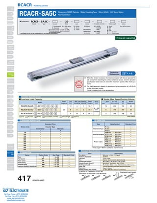
RCACR-SA5C Cleanroom ROBO Cylinder Slider Coupling Type 52mm Width 24V Servo Motor
Series Type Encoder Motor Lead Stroke Compatible Controllers Cable Length Option
N : None
P : 1m
S : 3m
M : 5m
X □□ : Custom
R □□ : Robot cable
50: 50mm See Options below
Power-saving
A1: ACON
RACON
ASEL
A3: AMEC
ASEP
〜
500: 500mm
(50mm pitch
increments)
(1) When the stroke increases, the maximum speed will drop to prevent the
ball screw from reaching the critical rotational speed. Use the actuator
specification table below to check the maximum speed at the stroke you
desire.
(2) The load capacity is based on operation at an acceleration of 0.3G (0.2G
for the 3mm-lead model).
This is the upper limit of the acceleration.
Model Stroke
Type Cable Symbol Standard Price
Standard Type
Special Lengths
Robot Cable
P (1m)
S (3m)
M (5m)
X06 (6m) ~ X10 (10m)
X11 (11m) ~ X15 (15m)
X16 (16m) ~ X20 (20m)
R01 (1m) ~ R03 (3m)
R04 (4m) ~ R05 (5m)
R06 (6m) ~ R10 (10m)
R11 (11m) ~ R15 (15m)
R16 (16m) ~ R20 (20m)
Max. Load Capacity Rated
Item Description
Ball screw ø10mm C10 grade
±0.02mm
0.1mm or less
Material: Aluminum (white alumite treated)
Ma: 18.6N∙m Mb: 26.6N∙m Mc: 47.5N∙m
Ma: 4.9N∙m Mb: 6.8N∙m Mc: 11.7N∙m
Ma direction: 150mm or less; Mb, Mc direction: 150mm or less
Low dust generation grease (both ball screw and guide)
Class 10 (0.1μm)
0~40°C, 85% RH or less (non-condensing)
L
Overhang Load Length
L
12 : 12mm
6 : 6mm
3 : 3mm
O I N
T
Notes on
Selection
(*) Based on a 5,000km service life.
Directions of Allowable Load Moments
Ma Mb Mc Ma Mc
–
–
–
–
–
–
–
–
–
–
–
* See page A-39 for cables for maintenance.
■ Configuration: RCACR SA5C 20
SA4D : Aluminum
base
SS4D : Steel base
Aluminum Base
P
20 : 20W servo
motor
I : Incremental
A : Absolute
Legend: 1 Encoder 2 Stroke 3 Compatible controller 4 Cable length 5 Options
1 Encoder & Stroke List 4 Cable List
5 Option List
Actuator Specifications
Incremental Absolute
–
–
–
–
–
–
–
–
–
–
–
–
–
–
–
–
–
–
–
–
I
50
100
150
200
250
300
350
400
450
500
A
Actuator Specifications
■ Lead and Load Capacity ■ Stroke, Max. Speed/Suction Volume
Standard Price
Stroke (mm) Encoder Type
(Unit: mm/s)
Motor
Output (W)
Lead
(mm) Horizontal (kg) Vertical (kg)
Thrust (N)
(mm)
RCACR-SA5C- 1 -20-12- 2 - 3 - 4 - 5
RCACR-SA5C- 1 -20-6- 2 - 3 - 4 - 5
RCACR-SA5C- 1 -20-3- 2 - 3 - 4 - 5
20
12
6
3
4
8
12
1
2
4
16.7
33.3
65.7
50 ~ 500
(50mm
increments)
Stroke
Lead
50 ~ 450
(50mm increments)
500
(mm)
Suction
Volume (Nl/min)
800 760 50
400 380 30
200 190 15
12
6
3
Name Option Code See Page Standard Price
B
FT
HS
LA
NM
VR
→ A-25
→ A-29
→ A-32
→ A-32
→ A-33
→ A-38
Brake
Foot bracket
Home sensor
Power-saving
Reversed-home
Intake port mounted on opposite side
–
–
–
–
–
–
* See page Pre-35 for an explanation of the naming convention.
P. A-5 Technical
References
* The absolute model can only use ASEL.
The simple absolute type is considered
an incremental model.
Drive System
Positioning Repeatability
Lost Motion
Base
Allowable Static Moment
Allowable Dynamic Moment (*)
Overhang Load Length
Grease Type
Cleanliness
Ambient Operating Temp./Humidity
417 RCACR-SA5C
Slider
Type
Mini
Standard
Controllers
Integrated
Rod
Type
Mini
Standard
Controllers
Integrated
Table/Arm
/Flat Type
Mini
Standard
Gripper/
Rotary Type
Linear Servo
Type
Cleanroom
Type
Splash-Proof
Controllers
PMEC
/AMEC
PSEP
/ASEP
ROBO
NET
ERC2
PCON
ACON
SCON
PSEL
ASEL
SSEL
XSEL
Pulse Motor
Servo Motor
(24V)
Servo Motor
(200V)
Linear
Servo Motor
Sold & Serviced By:
ELECTROMATE
Toll Free Phone (877) SERVO98
Toll Free Fax (877) SERV099
www.electromate.com
sales@electromate.com
2. 40
30
19
2-ø4H7 depth 6 4-M4 depth 9
9
4-ø 4.5 ø8 deep counterbore,
depth 4.5 (for mounting actuator)*4
26
26
10.2 14.5 M 14.5
90 15.5
Actuator width: 52
+0.012
4
(50)
Base end-face
RCACR ROBO Cylinder
*4 If the actuator is secured using only the mounting holes provided on the top surface of the
base, the base may twist to cause abnormal sliding of the slider, or may produce
abnormal noise. Therefore, when using the mounting holes on the top surface of the base,
keep the stroke at 300mm or less.
Base end-face
L
25.7
Ma moment
offset reference
position*3
Base
end-face Base end-face
14.5 R U×100P (All strokes except 50) 14.5
m-M4 depth 7 P (pitch of ø4 hole and oblong hole)
■ Dimensions and Weight by Stroke * Adding a brake will increase the actuator's weight by 0.3kg.
No Brake
With Brake
No Brake
With Brake
M
N
P
R
U
m
3 Compatible Controllers
The RCACR series actuators can operate with the controllers below. Select the controller according to your usage.
For Special Orders P. A-9
Cable joint
connector*1
Slot ø8 hole
Symmetric
Standard (optional)
Applicable tube OD ø6
18.2
45
st
3 3
0
5
Secure at least 100
Reference
surface
A
5
(52)
50 Bottom of base Motor section width: 52
Motor section height: 48
1
32
20
Slider height: 50
40
26
1
ME SE
Home ME*2
Details of the slotted area
for adjusting slider position
Details of section A Details of oblong hole
(Actuator's reference side)
(240)
39
±0.02
Incremental 84.2 (123.2 if brake-equipped)
Absolute 99.2 (138.2 if brake-equipped)
N (ø4 hole pitch)
Oblong hole depth 5
from bottom of base
26
2-ø4H7 depth 5 from bottom of base
50 (when stroke is 50)
50
(Reamer hole
tolerance ±0.02)
Dimensions
*1 The motor-encoder cable is connected here. See page A-39 for details on cables.
*2 After homing, the slider moves to the ME; therefore, please watch for any interference with the surrounding objects.
ME: Mechanical end SE: Stroke end
*3 Reference position for calculating the moment Ma.
Stroke 50 100 150 200 250 300 350 400 450 500
L
Incremental
Absolute
Weight (kg)
265.4
304.4
280.4
319.4
142
50
35
42
−
4
1.3
315.4
354.4
330.4
369.4
192
100
85
42
1
4
1.4
365.4
404.4
380.4
419.4
242
100
85
92
1
4
1.5
415.4
454.4
430.4
469.4
292
200
185
42
2
6
1.6
465.4
504.4
480.4
519.4
342
200
185
92
2
6
1.7
515.4
554.4
530.4
569.4
392
300
285
42
3
8
1.8
565.4
604.4
580.4
619.4
442
300
285
92
3
8
1.9
615.4
654.4
630.4
669.4
492
400
385
42
4
10
2
665.4
704.4
680.4
719.4
542
400
385
92
4
10
2.1
715.4
754.4
730.4
769.4
592
500
485
42
5
12
2.2
Name External View Model Description Max. Positioning Points Input Voltage Power Supply Capacity Standard Price See Page
* This is for the single-axis ASEL.
* 1 is a placeholder for the encoder type (I: incremental / A: absolute).
* 2 is a placeholder for the code *LA* if the power-saving option is specified.
Solenoid Valve Type
AMEC-C-20I2-NP-2-1 Easy-to-use controller, even for beginners
3 points
AC100V 2.4A rated – → P477
ASEP-C-20I2-NP-2-0 Operable with same signal as solenoid valve.
Supports both single and double solenoid types.
No homing necessary with simple absolute type.
DC24V
(Standard)
1.3A rated
4.4A max.
(Power-saving)
1.3A rated
2.5A max.
–
→ P487
Splash-Proof
Solenoid Valve Type
ASEP-CW-20I2-NP-2-0 –
Positioner Type ACON-C-20I2-NP-2-0
Positioning is possible for up to 512 points 512 points
–
→ P535
Safety-Compliant
Positioner Type
ACON-CG-20I2-NP-2-0 –
Pulse Train Input Type
(Differential Line Driver)
ACON-PL-20I2-NP-2-0
Pulse train input type with
differential line driver support
(−)
–
Pulse Train Input Type
(Open Collector)
ACON-PO-20I2-NP-2-0
Pulse train input type with
open collector support –
Serial
Communication Type
ACON-SE-20I2-N-0-0 Dedicated to serial communication 64 points –
Field Network Type RACON-202 Dedicated to field network 768 points – → P503
Program Control
Type
ASEL-C-1-2012-NP-2-0
Programmed operation is possible
Operation is possible on up to 2 axes
1500 points – → P567
RCACR-SA5C 418
Slider
Type
Mini
Standard
Controllers
Integrated
Rod
Type
Mini
Standard
Controllers
Integrated
Table/Arm
/Flat Type
Mini
Standard
Gripper/
Rotary Type
Linear Servo
Type
Cleanroom
Type
Splash Proof
Controllers
PMEC
/AMEC
PSEP
/ASEP
ROBO
NET
ERC2
PCON
ACON
SCON
PSEL
ASEL
SSEL
XSEL
Pulse Motor
Servo Motor
(24V)
Servo Motor
(200V)
Linear
Servo Motor
Sold & Serviced By:
ELECTROMATE
Toll Free Phone (877) SERVO98
Toll Free Fax (877) SERV099
www.electromate.com
sales@electromate.com