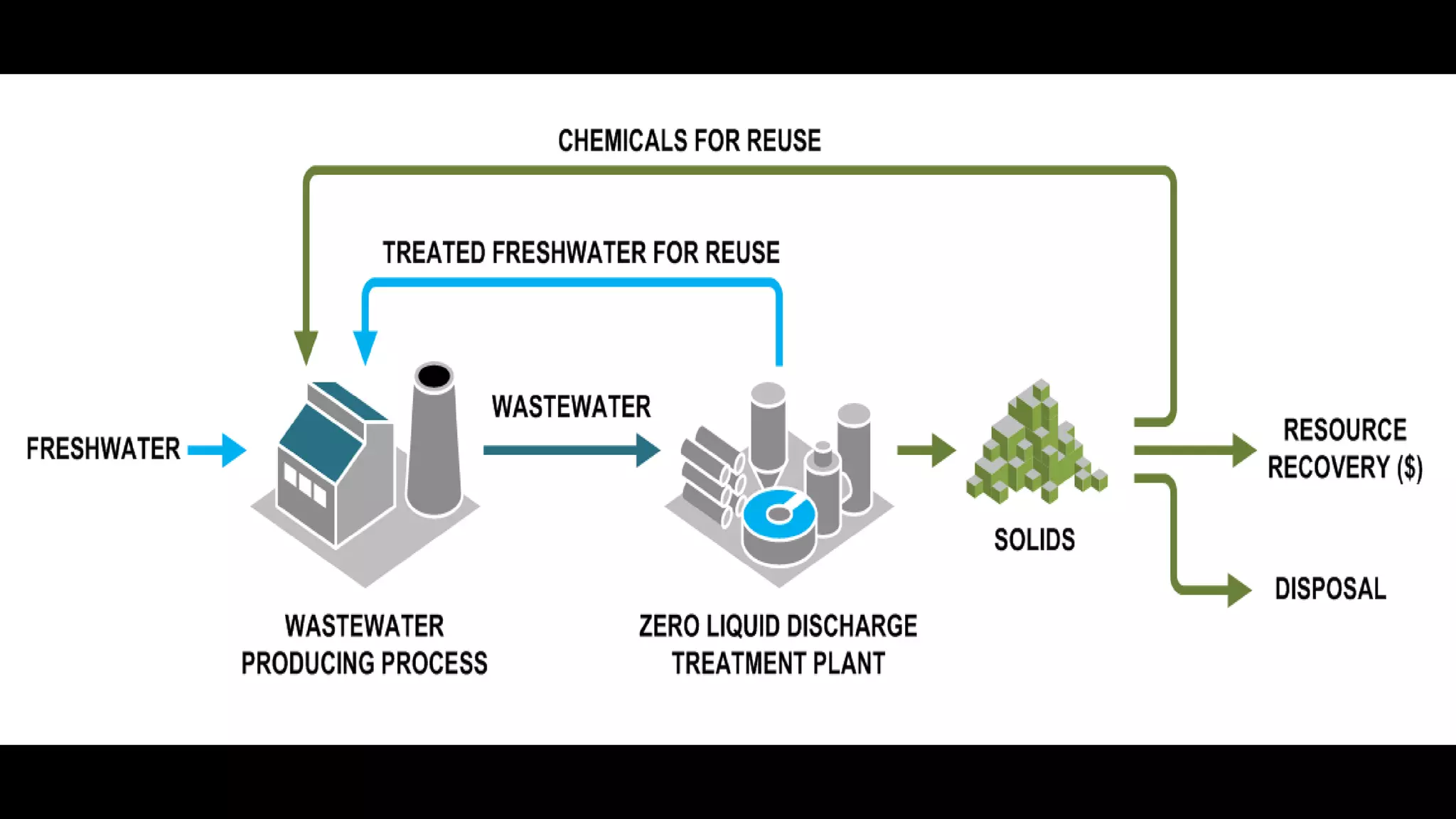
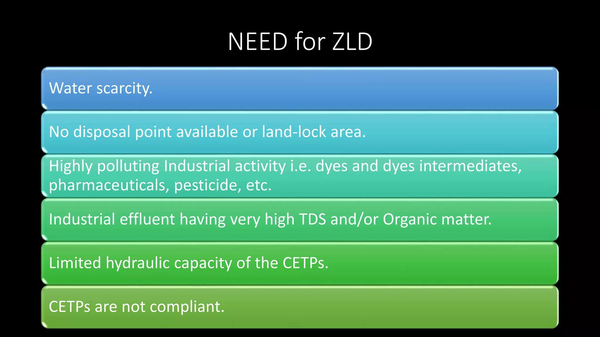
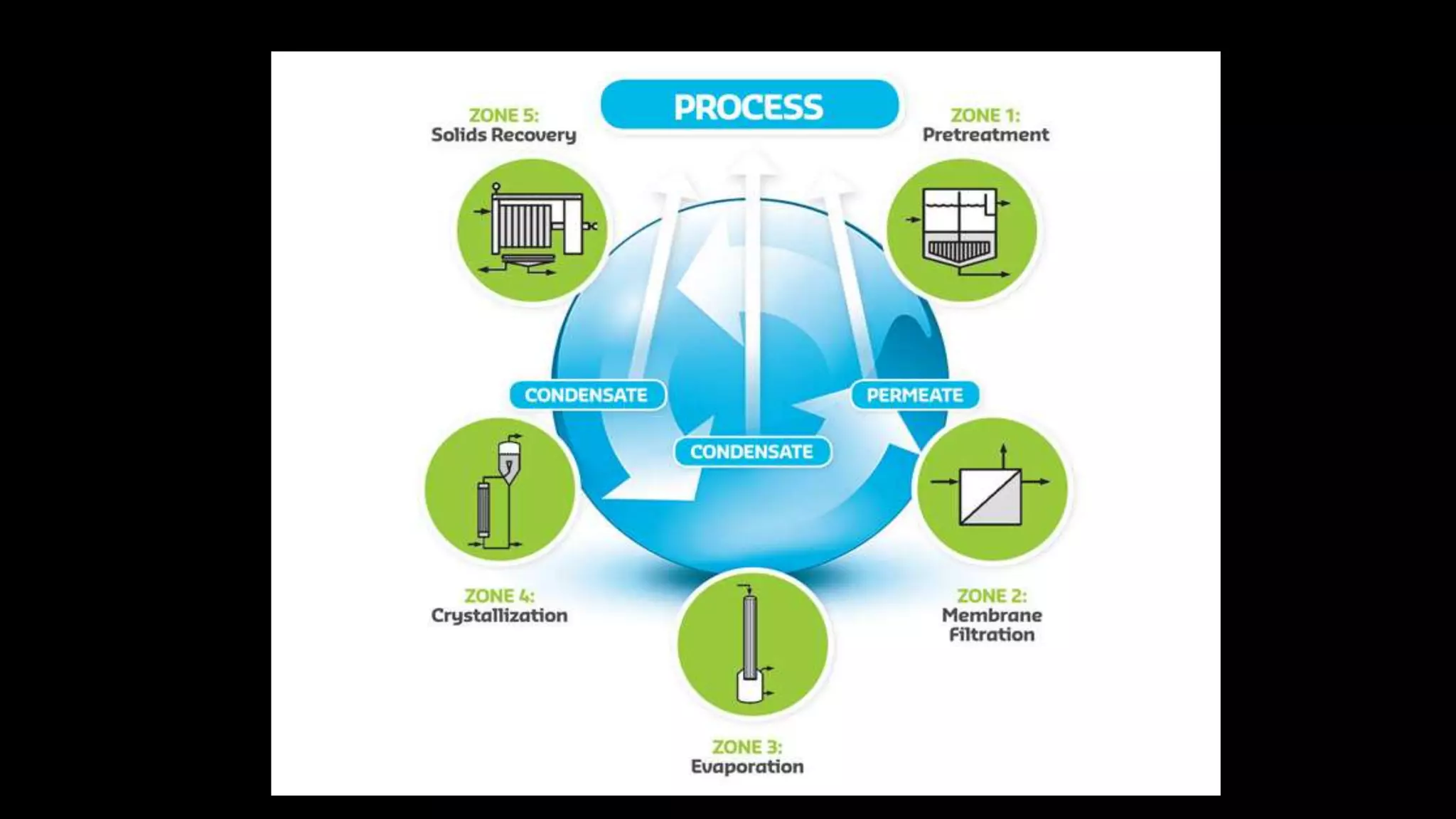
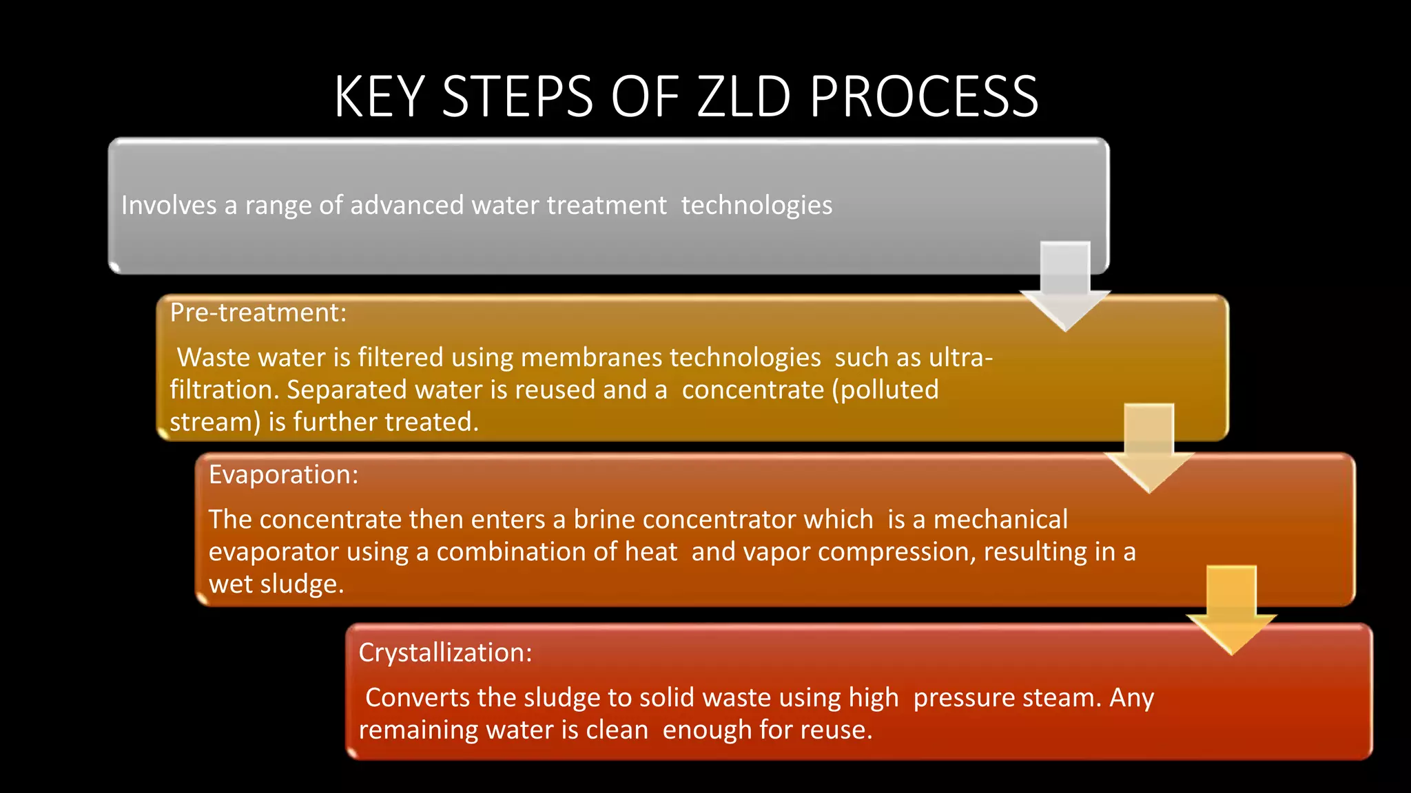
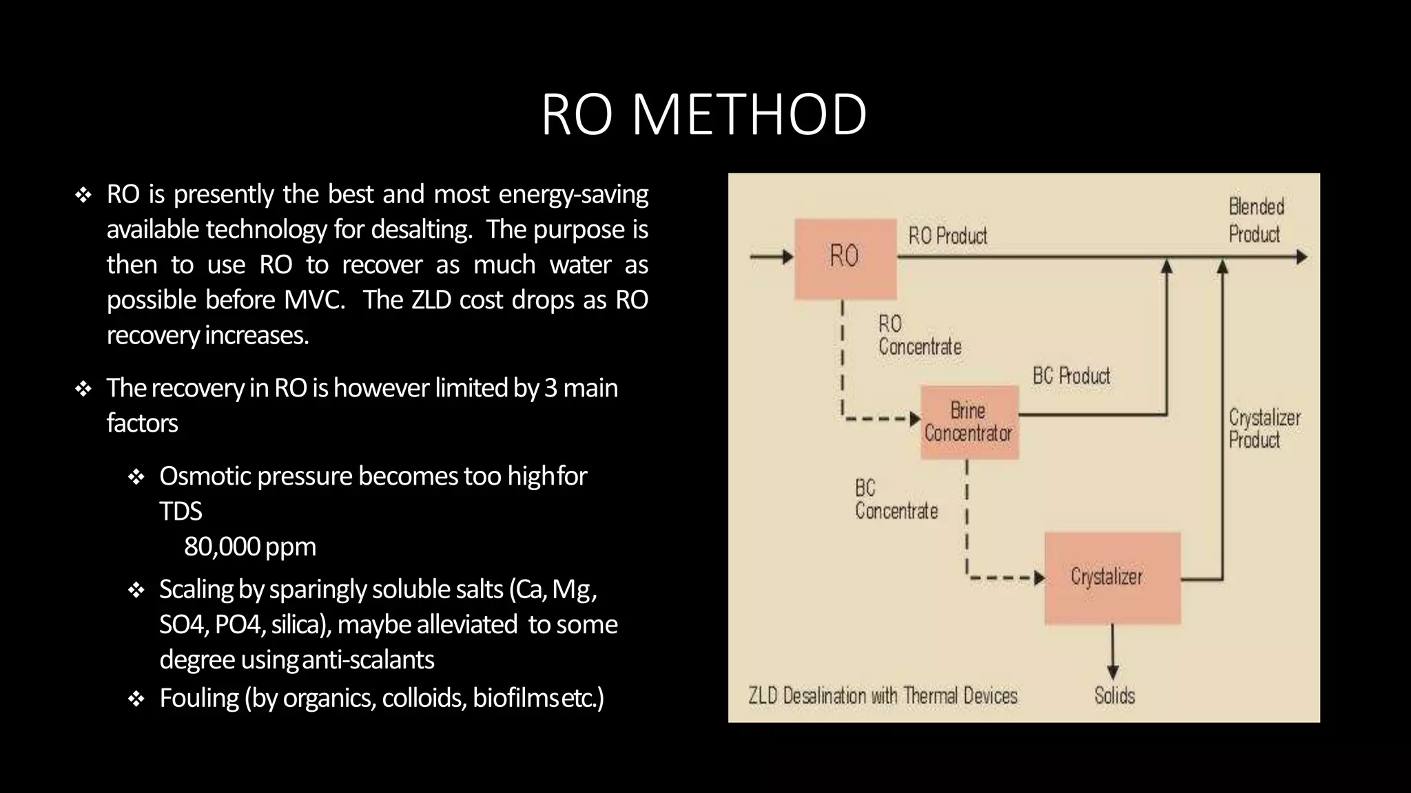
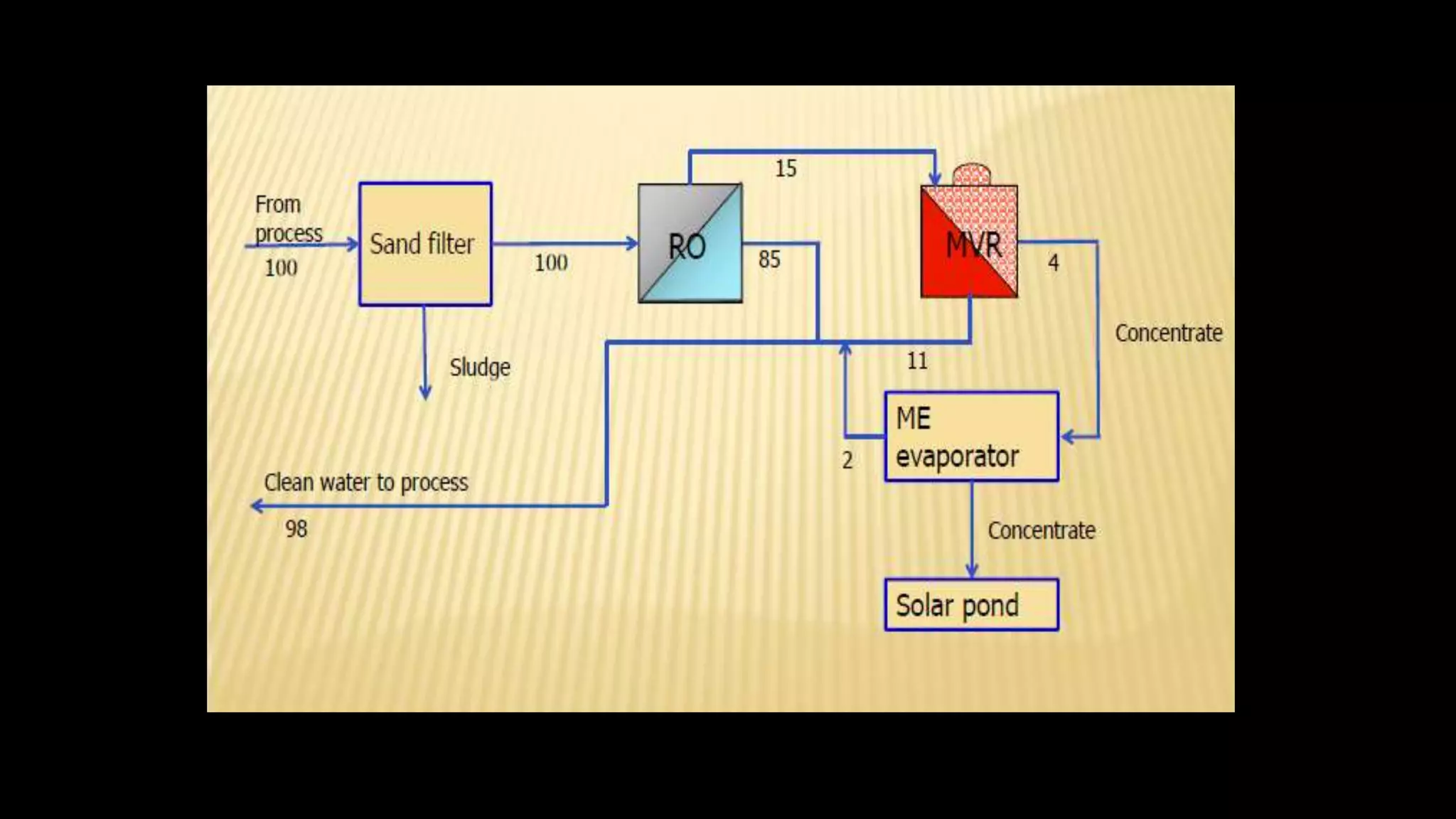
This document discusses zero liquid discharge (ZLD) systems. It provides background on the need for ZLD due to water scarcity issues. It then describes the key steps in a ZLD process, which involves pre-treatment, evaporation, and crystallization to separate water for reuse from solids for disposal. Common technologies used are reverse osmosis, mechanical vapor recompression, and multiple effect evaporators. The document concludes with two case studies of industries that have implemented ZLD systems successfully.
2. CONTENTS
CONCEPT OF ZLD
BACKGROUND
SOME FACTS
NEED FOR ZLD
BENEFITS OF ZLD
ZLD OPTIONS
KEY STEPS OF ZLD
CASE STUDIES
EMERGING TECHNOLOGIES IN ZLD CONCEPT
APPLICATION OF ZLD
CHALLENGES OF ZLD
REFRENCES
3. CONCEPT OF ZLD
• Broadly defined as the separation of
an aqueous waste to its water and
solids components.
• Wherein, the water is reused and
solids (usually with some moisture)
are disposed as a waste or by-
product.
An industrial
plant
without
discharge of
waste
waters
4.
5. BACKGROUND
• Water is a finite resource and cannot be replaced/duplicated.
• Water resources are theoretically ‘renewable’ through hydrological
cycle, but pollution, contamination, climate change, temporal and
seasonal variations have affected the water quality and reduced the
amount of ‘usable water’.
• The ground water levels are declining very fast and Rainfall is
unevenly distributed over time and space.
6.
7. SOME FACTS
India has more than 18 percent of the world’s population, but has only 4 percent of world’s
renewable water resources with 2.4 percent of world’s land area.
India With a growing population and rising needs of a fast developing nation as well as the given
indicators of the impact of climate change, per capita availability of water is likely to go down
from 1545 cubic metre per year in 2011 to 1341 cubic metre per year in 2025.
Also region wise it varies from 10 cm rainfall in Rajasthan to 1000 cm in North Eastern Region.
There are further limits on utilizable quantities of water owing to uneven distribution over time,
as 75 percent of annual rainfall is received in just four months.
The increasing demand of water for various purposes will further strain with the possibility of
deepening water conflicts among different user groups as drinking water need is going to rise by
44 percent, irrigation need by 10 percent, industry need by 81 percent respectively by 2025.
8. NEED for ZLD
Water scarcity.
No disposal point available or land-lock area.
Highly polluting Industrial activity i.e. dyes and dyes intermediates,
pharmaceuticals, pesticide, etc.
Industrial effluent having very high TDS and/or Organic matter.
Limited hydraulic capacity of the CETPs.
CETPs are not compliant.
9. BENEFITS OF ZLD
Water Conservation / Generates make up water (reduces demand of fresh water)
Reduces the wastewater discharge i.e. reduces water pollution
Preferred option for industry where disposal of effluent is major bottleneck Prevents exploitation of hydraulic capacity of
disposal system
Reduces cost of disposal at common infrastructure
Separation of salts / residual solvents improve efficiency of ETP and CETP Separated solids valuable by-product which helps
in reducing the pay back period Mixed solvent separated in stripper can be reused or used as AFR / Co-processing.
Ease in getting environmental permissions.
More focus on production/ business rather than tracking after regulatory authorities
10. ZLD OPTIONS
Characterization
and segregation
of effluents.
Use of waste
stream as raw
material.
Conventional
P+S+T treatment
Salt separation
by centrifuge
Alternate
evaporative
method (MVC)
Evaporative
thermal
process(MEE)
Water spray
drier
Coprocessing
Incineration
11.
12. KEY STEPS OF ZLD PROCESS
Involves a range of advanced water treatment technologies
Pre-treatment:
Waste water is filtered using membranes technologies such as ultra-
filtration. Separated water is reused and a concentrate (polluted
stream) is further treated.
Evaporation:
The concentrate then enters a brine concentrator which is a mechanical
evaporator using a combination of heat and vapor compression, resulting in a
wet sludge.
Crystallization:
Converts the sludge to solid waste using high pressure steam. Any
remaining water is clean enough for reuse.
13. RO METHOD
RO is presently the best and most energy‐saving
available technology for desalting. The purpose is
then to use RO to recover as much water as
possible before MVC. The ZLD cost drops as RO
recoveryincreases.
TherecoveryinROishoweverlimitedby3main
factors
Osmotic pressurebecomestoo highfor
TDS
80,000ppm
Scalingbysparinglysolublesalts(Ca,Mg,
SO4,PO4,silica),maybealleviated tosome
degreeusinganti‐scalants
Fouling(byorganics,colloids,biofilmsetc.)
15. Process wastewater is fed by the feed
pump through the feedstock heat
exchanger and into the circulating
stream. The feedstock heat exchanger
is used to heat the wastewater by
transferring sensible heat from the hot
condensate to the cooler feed.
The recirculation pump circulates
wastewater from the separation tank
through the main heat exchanger, to
the orifice plate, and back into the
separation tank. The latent heat from
the compressed vapor is transferred to
the wastewater via the main heat
exchanger.
The liquid and vapor then flow to the
separation tank where they are
separated. The liquid steam exits the
tank at the bottom and flows back to
the recirculation pump. The vapor
stream exits the tank at the top and
flows to the vapor compressor(s).
The vapor compressor compresses the
vapor (raising the temperature and
pressure), and sends the vapor to the
main heat exchanger, where it transfers
its latent heat to the wastewater in the
recirculation loop.
High temperature condensate exits the
main heat exchanger and flows to the
condensate tank, where any remaining
vapor is separated. The hot condensate
is then pumped to the feedstock heat
exchanger, where it transfers sensible
heat to the incoming feed wastewater.
Upon reaching steady-state at the
target concentration, the concentrated
wastewater is purged from the
recirculation loop, using the residue
valve. Depending on the energy
balance, energy can be added to the
system by electric heaters / process
steam or excess energy can be
removed from the system by the steam
relief valve.
17. Process
MVRE uses a
compressor to
increase the
pressure of the
water vapor, or
steam, produced.
An increase in
vapor pressure
increases the
condensation
temperature of the
steam, rendering it
usable to heat the
original mixture in
a heat-transfer
apparatus.
It is this resulting
temperature
difference
produced by
compressing the
steam that enables
a highly efficient
heat transfer to
occur.
As the steam
condenses in the
heating chamber, it
releases its latent
heat of
vaporization to
further heat the
original mixture,
which in turn
produces more
steam. This
recycling of heat is
what renders
MVRE so efficient.
20. CASE STUDY :ARVIND MILLS,SANTEJ
AHMEDABAD
The Arvind Limited , modern and state of
art composite textile complex, is set up in
1997, at Village Santej of Gandhinagar
District in Gujarat. Total Area is 421 Acres.
Main products of this Textile complex is
• Shirting fabrics
• Knit Fabrics
• Cotton Trousers Fabric.
• Denim Fabric
21. • Basically this area Khakharia is water scare area and no water was
available except bore well water . More over there was no discharge
point was available for effluent discharge after treatment.
• So being a textile industry and a intensive water usage this complex is
planned with the objective of minimizing water consumption by
recycling entire effluent, thus the net withdrawal of the water from
bore wells is limited to only evaporation losses.
• No discharge point was available for the treated effluents in
1997.Hence , Effluent Recycle Plant has been established to recycle
the waste water fit for process reuse , for CPP, cooling tower and also
for plantation and gardening in the complex.
• Cost of the ETP Plant is 100 Crores with 45 Acres land area covered in
1997.
22. The textile operations need
Process water and produce
waste water that is colored ,
alkaline in nature and having
COD and BOD load and is
amicable to conventional
treatment.
Capacity of waste water
• Treatment and Recycling
Plant designed for the
complex is 17000 m3/day
23. SLUDGE MANAGEMENT
Sludge is de-watered through Belt Press and Dried and disposed to
TSDF site of NEPL , Odhav
24. RO REJECT MANAGEMENT
• Total 94 % Good water is recovered by 3 stage RO system @ 65 Rs/M3
which includes all variable and fixed cost.
• The 6 % Reject is subject to treat in MVRE Plant Total 35 Crore
Invested.
• MVRE Plant includes MVR Evaporator and MEE-Crystallizer for Salt
Recovery and Re-use.
• The Operation cost is 750 Rs/M3.
• The Distilled water is used for Steam generation in Boilers.
• The Dry salt is pure, so used in Dyeing process.
26. SALT RECOVERY AND REUSE
• Resource Recovery : Recovery of
salt from RO Reject by new MVR
Technology at cost of 35 Cr Rs.
• Daily 25 MT/Day Pure GlauberSalt
is Recovered.
27. RE-USE OF SEWAGE
• Arvind Garment Exports Pvt Ltd, Near Dehgam will use 2000 M3/Day
Raw sewage of town and after in house treatment will be used in
Garment washing.
• In Ankur Division , Ahmedabad is using 1500 M3/Day Raw sewage in
January-2016 after in house treatment for textile fabric processing .
• 1600 M3/day Sewage Effluent generated from 5000 Nos of Arvind &
Smart value homes LLP township project with TATA housing near
Arvind Santej Plant. used to produce DM water against Raw water
presently used in Arvind. This will reduce raw water extraction from
Ground to 900 M3/day.
28. RAIN WATER RECHARGE PONDS
• Two Ground water recharge ponds of 5700m3 &
9000 m3 capacity are excavated in 1999-2000 to
protect the natural resource.
Rain Water recharged from 1999-2014
Total 768505 M3
30. CASE STUDY :BOMBAY RAYON TEXTILE
DYEING , BANGALORE
Process:
• Bleaching, Neutralizing, Washing, Dyeing, Acid washing, Washing,
• Soaping, Hot washing, Fixing & Softening.
Effluent:
• Sand filter to trap suspended solids
• Pre-concentration in RO, recycle of water to process
• Reject to MVR evaporation, recycle of condensate to process
• Concentrate to ME evaporator for final concentration, recycle of condensate to
process
• Concentrate to solar drying pond
• Plant capacity 3 x 500KLD In operation since year 2006
31.
32. EMERGING TECHNOLOGIES OF ZLD
SPARRO PROCESS
•Slurry Precipitation and Recycle Reverse Osmosis (SPARRO)
• Developed for treating hard waste water from mining industry