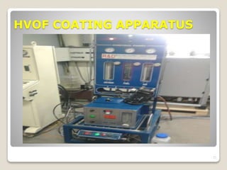
DISSERTATION REPORT
ON
COATING EVALUATION OF THE
SLURRY EROSION BEHAVIOUR IN
HYDROPOWER PLANT
PRESENTED BY – YOGENDRA KUMAR
UNI. ROLL NO. -2194210
COURSE- M TECH MECHANICAL (MACHINE DESIGN)
GUIDE – Mr. B.N. AGRAWAL (HOD ME)
1
INTRODUCTION
 Hydro power plants suffer from silts erosion of underwater parts.
 Particularly in monsoon season,
 90% of the silt particle size is 0.2mm and contains quartz with
hardness 7-8 on Mohs scale value.
 The various parts of the plant are subjected to an environment
that contains silt particles carried by water.
 Land erosion and landslides due to heavy rain in monsoon.
2
MODEL OF HYDROPOWER PLANT
3
WEAR
Wear is defined as the progressive volume loss of
material from target surface.
It may be due to erosion, abrasion or corrosion.
The wear due to corrosion is caused by chemical
reactions,
which can be prevented by adopting suitable
measures.
The wear due to erosion or abrasion can be
minimized by controlling the affecting parameters.
4
TYPES OF EROSION WEAR
A. Adhesive Wear
B. Abrasive Wear
C. Corrosive Wear
D. Surface Fatigue Wear
E. Erosive wear
5
TYPES OF EROSION
EROSION
Slurry
Erosion
Liquid
Impingement
Cavitation
Erosion
Solid particle
6
FACTORS EFFECTING SLURRY EROSION
 Operating conditions.
 Erodent’s.
 Properties of target surface.
7
ERODED BLADES AT SALAL &
BIRACIAL POWER STATIONS
8
MATERIALS USED IN TURBINE
BLADE
9
PROPRTIES OF MATERIALS
A. High tensile strength
B. High fatigue strength
C. High hardness
D. High resilience
10
SURFACE COATING TECHIQUES
The service life of any component can be improved
by providing a protective coating on the surface
exposed to solid particle impact.
11
Electroplating
Physical vapour deposition
Chemical vapour deposition
Thermal spray
ELECTROPLATING
12
ADVANTAGES
1. well-understood
technology
2. good conductors of
electricity.
DISADVANTAGES
1. Obtaining a uniform
thickness with
electroplating is
difficult.
2. Slow rate of deposition
PHYSICAL VAPOR DEPOSITION
ADVANTAGES
environmentally
friendly
better quality than
electroplating
13
DISADVANTAGES
dissipate large heat
loads
High capital costs
CHEMICAL VAPOR DEPOSITION
In this process, the substrate is placed inside a reactor to which a
number of gases are supplied. The fundamental principle of the
process is that a chemical reaction takes place between the source
gases. The product of that reaction is a solid material with
condenses on all surfaces inside the reactor.
14
THERMAL SPRAY
A. Thermal spraying techniques are coating processes in
which melted (or heated) materials are sprayed onto a
surface.
B. The "feedstock" (coating precursor) is heated by
electrical (plasma or arc) or chemical means
(combustion flame).
C. Thermal spraying can provide thick coatings (approx.
thickness range is 20 micrometers to several mm,
depending on the process and feedstock).
15
The Plasma Spray Process is basically the spraying of
molten or heat softened material onto a surface to
provide a coating.
16
PLASMA SPRAYING
DETONATION THERMAL SPRAYING PROCESS
detonation gun consists of a long water cooled barrel. This
barrel has valves for inlet of powder and gases. The oxygen
and fuel (most commonly acetylene) is feed to this barrel
through gas inlet valve. The powder is also fed to this
barrel along with gases.
17
WIRE ARC SPRAY
Wire arc spray is a form of thermal spraying where two
consumable metal wires are fed independently into the
spray gun. These wires are then charged and an arc is
generated between them.
18
FLAME SPRAYING
In this method, the combustion of fuel gas takes place in a
torch which is used to generate a hot flame. The gas and
powder can be introduced axially or perpendicularly to the
torch. The particles in molten state accelerate towards the
work piece.
19
High Velocity Oxygen Fuel(HVOF)
Thermal Spray Process
A mixture of gaseous or liquid fuel and oxygen is fed into a
combustion chamber, where they are ignited and combusted
continuously. The resultant hot gas at a high pressure emanates
through a converging–diverging nozzle and travels through a
straight section.
20
COLD SPRAY COATING
The Cold Spray process basically uses the energy stored in high
pressure compressed gas to propel fine powder particles at very high
velocities (500 - 1500 m/s). Compressed gas (usually helium) is fed via a
heating unit to the gun where the gas exits through a specially designed
nozzle (Level type convergent-divergent nozzle mostly) at very high
velocity
21
OBJECTIVE OF THIS THESIS
A. Our main objective is reduce the level of erosion from
turbine blades and also increase the efficiency of
hydropower plant.
B. HVOF thermal spray coating technique is used for
coating.
C. The various coatings are WC-Co-Cr, Cr2C3+NiCr and
diamalloy.
D. The jet type erosion tester is used to study the erosion
wear of base material with and without coating with
different compositions.
E. It is experimentally observed that HVOF thermal spray
coating on 16/5 steel helps in reducing the erosion wear
of hydro turbine materials.
22
EXPERIMENTAL WORK
23
WORKING OF JET EROSION TESTER
24
In jet erosion, testing a high velocity jet strikes a flat
specimen at some adjustable angle. In jet erosion
tests, the amount of material removed is determined
by the weight loss. The material which accumulates
on the specimen surface interferes with the incoming
particle. The weight loss of the specimen
corresponds to the average erosion over the surface.
PREPRATION OF SAMPLES
25
A. The steel mostly used in modern turbine industry i.e.
16Cr5Ni is to be used for testing purpose.
B. The high velocity oxy fuel (HVOF) thermal spray
technique has been used for coating. Both sides of the
samples were used for testing for coated and non coated
materials.
C. Blasting of samples is necessary before applying the
coating so as to supplement the adhesion of the coatings
to the surface of sample
ABRASIVE BLASTING MACHINE
26
HVOF COATING APPARATUS
27
TEST PROCEDURE
28
A. Cleaning the specimen properly
B. Drying, if required
C. Weighing the specimen (initial weight)
D. Clamp the specimen in test rig
E. Setting the holder at required angle
F. Weight the required sand as per concentration of
slurry
G. Mixing the proper amount of water and sand in
tank
H. Adjust the flow rate to obtain desired value of
velocity
I. Weighing the specimen after erosion to measure
the mass loss
J. Repeat the steps from D to I as per requirement.
CONCLUSIONS
29
1. Erosion wear rate of 16/5 steel is found uniform with
respect to time.
2. For 16/5 uncoated steel maximum erosion is at 30 impact
angle and minimum at 90.
3. For all coatings maximum erosion is at 90
4. Only WC-Co-Cr coating has minimum erosion at 60
5. At higher angles WC-Co-Cr coated steel shows better
performance but at lower angles +NiCr shows a slightly
better performance.
FUTURE SCOPRE
30
A. The erosion wear studies can be performed with other
coating techniques.
B. The computational approach can be used to simulate the
similar work with different operating conditions.
C. The effect of erosion wear of pump impeller of ash
disposal system can be studied.
D. The similar erosion wear studies can be extended by
using other types of pot tester and different slurry
concentration.
31
...........

Yogendra mtech ppt erosion techniques

  • 1.
    DISSERTATION REPORT ON COATING EVALUATIONOF THE SLURRY EROSION BEHAVIOUR IN HYDROPOWER PLANT PRESENTED BY – YOGENDRA KUMAR UNI. ROLL NO. -2194210 COURSE- M TECH MECHANICAL (MACHINE DESIGN) GUIDE – Mr. B.N. AGRAWAL (HOD ME) 1
  • 2.
    INTRODUCTION  Hydro powerplants suffer from silts erosion of underwater parts.  Particularly in monsoon season,  90% of the silt particle size is 0.2mm and contains quartz with hardness 7-8 on Mohs scale value.  The various parts of the plant are subjected to an environment that contains silt particles carried by water.  Land erosion and landslides due to heavy rain in monsoon. 2
  • 3.
  • 4.
    WEAR Wear is definedas the progressive volume loss of material from target surface. It may be due to erosion, abrasion or corrosion. The wear due to corrosion is caused by chemical reactions, which can be prevented by adopting suitable measures. The wear due to erosion or abrasion can be minimized by controlling the affecting parameters. 4
  • 5.
    TYPES OF EROSIONWEAR A. Adhesive Wear B. Abrasive Wear C. Corrosive Wear D. Surface Fatigue Wear E. Erosive wear 5
  • 6.
  • 7.
    FACTORS EFFECTING SLURRYEROSION  Operating conditions.  Erodent’s.  Properties of target surface. 7
  • 8.
    ERODED BLADES ATSALAL & BIRACIAL POWER STATIONS 8
  • 9.
    MATERIALS USED INTURBINE BLADE 9
  • 10.
    PROPRTIES OF MATERIALS A.High tensile strength B. High fatigue strength C. High hardness D. High resilience 10
  • 11.
    SURFACE COATING TECHIQUES Theservice life of any component can be improved by providing a protective coating on the surface exposed to solid particle impact. 11 Electroplating Physical vapour deposition Chemical vapour deposition Thermal spray
  • 12.
    ELECTROPLATING 12 ADVANTAGES 1. well-understood technology 2. goodconductors of electricity. DISADVANTAGES 1. Obtaining a uniform thickness with electroplating is difficult. 2. Slow rate of deposition
  • 13.
    PHYSICAL VAPOR DEPOSITION ADVANTAGES environmentally friendly betterquality than electroplating 13 DISADVANTAGES dissipate large heat loads High capital costs
  • 14.
    CHEMICAL VAPOR DEPOSITION Inthis process, the substrate is placed inside a reactor to which a number of gases are supplied. The fundamental principle of the process is that a chemical reaction takes place between the source gases. The product of that reaction is a solid material with condenses on all surfaces inside the reactor. 14
  • 15.
    THERMAL SPRAY A. Thermalspraying techniques are coating processes in which melted (or heated) materials are sprayed onto a surface. B. The "feedstock" (coating precursor) is heated by electrical (plasma or arc) or chemical means (combustion flame). C. Thermal spraying can provide thick coatings (approx. thickness range is 20 micrometers to several mm, depending on the process and feedstock). 15
  • 16.
    The Plasma SprayProcess is basically the spraying of molten or heat softened material onto a surface to provide a coating. 16 PLASMA SPRAYING
  • 17.
    DETONATION THERMAL SPRAYINGPROCESS detonation gun consists of a long water cooled barrel. This barrel has valves for inlet of powder and gases. The oxygen and fuel (most commonly acetylene) is feed to this barrel through gas inlet valve. The powder is also fed to this barrel along with gases. 17
  • 18.
    WIRE ARC SPRAY Wirearc spray is a form of thermal spraying where two consumable metal wires are fed independently into the spray gun. These wires are then charged and an arc is generated between them. 18
  • 19.
    FLAME SPRAYING In thismethod, the combustion of fuel gas takes place in a torch which is used to generate a hot flame. The gas and powder can be introduced axially or perpendicularly to the torch. The particles in molten state accelerate towards the work piece. 19
  • 20.
    High Velocity OxygenFuel(HVOF) Thermal Spray Process A mixture of gaseous or liquid fuel and oxygen is fed into a combustion chamber, where they are ignited and combusted continuously. The resultant hot gas at a high pressure emanates through a converging–diverging nozzle and travels through a straight section. 20
  • 21.
    COLD SPRAY COATING TheCold Spray process basically uses the energy stored in high pressure compressed gas to propel fine powder particles at very high velocities (500 - 1500 m/s). Compressed gas (usually helium) is fed via a heating unit to the gun where the gas exits through a specially designed nozzle (Level type convergent-divergent nozzle mostly) at very high velocity 21
  • 22.
    OBJECTIVE OF THISTHESIS A. Our main objective is reduce the level of erosion from turbine blades and also increase the efficiency of hydropower plant. B. HVOF thermal spray coating technique is used for coating. C. The various coatings are WC-Co-Cr, Cr2C3+NiCr and diamalloy. D. The jet type erosion tester is used to study the erosion wear of base material with and without coating with different compositions. E. It is experimentally observed that HVOF thermal spray coating on 16/5 steel helps in reducing the erosion wear of hydro turbine materials. 22
  • 23.
  • 24.
    WORKING OF JETEROSION TESTER 24 In jet erosion, testing a high velocity jet strikes a flat specimen at some adjustable angle. In jet erosion tests, the amount of material removed is determined by the weight loss. The material which accumulates on the specimen surface interferes with the incoming particle. The weight loss of the specimen corresponds to the average erosion over the surface.
  • 25.
    PREPRATION OF SAMPLES 25 A.The steel mostly used in modern turbine industry i.e. 16Cr5Ni is to be used for testing purpose. B. The high velocity oxy fuel (HVOF) thermal spray technique has been used for coating. Both sides of the samples were used for testing for coated and non coated materials. C. Blasting of samples is necessary before applying the coating so as to supplement the adhesion of the coatings to the surface of sample
  • 26.
  • 27.
  • 28.
    TEST PROCEDURE 28 A. Cleaningthe specimen properly B. Drying, if required C. Weighing the specimen (initial weight) D. Clamp the specimen in test rig E. Setting the holder at required angle F. Weight the required sand as per concentration of slurry G. Mixing the proper amount of water and sand in tank H. Adjust the flow rate to obtain desired value of velocity I. Weighing the specimen after erosion to measure the mass loss J. Repeat the steps from D to I as per requirement.
  • 29.
    CONCLUSIONS 29 1. Erosion wearrate of 16/5 steel is found uniform with respect to time. 2. For 16/5 uncoated steel maximum erosion is at 30 impact angle and minimum at 90. 3. For all coatings maximum erosion is at 90 4. Only WC-Co-Cr coating has minimum erosion at 60 5. At higher angles WC-Co-Cr coated steel shows better performance but at lower angles +NiCr shows a slightly better performance.
  • 30.
    FUTURE SCOPRE 30 A. Theerosion wear studies can be performed with other coating techniques. B. The computational approach can be used to simulate the similar work with different operating conditions. C. The effect of erosion wear of pump impeller of ash disposal system can be studied. D. The similar erosion wear studies can be extended by using other types of pot tester and different slurry concentration.
  • 31.