Download to read offline
![Harbinder Singh et al Int. Journal of Engineering Research and Applications www.ijera.com
ISSN : 2248-9622, Vol. 4, Issue 5( Version 1), May 2014, pp.138-142
www.ijera.com 138 | P a g e
Steering Wheel Shaped Frequency Reconfigurable Antenna for
Cognitive Radio
Harbinder Singh1
, Ranju Kanwar2
, Malika Singh3
1
(M. Tech Student, Department of ECE, PCET, Punjab, India)
2, 3
(Assistant Professor, Department of ECE, PCET, Punjab, India)
ABSTRACT
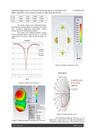
This paper depicts an outline to design a novel compact and low profile frequency reconfigurable microstrip
patch antenna for possible applications in cognitive radio systems to act as a fast switching antenna capable of
operating in seven different frequencies in the range of 6.25 to 8.25 GHz. The antenna structure comprises a
center rectangular encircled patch, in which rectangular patch is driven patch and the encirclement is for
frequency reconfigure ability. The reconfiguration ability of the antenna is obtained by placing four radio
frequency micro-electromechanical system (RF-MEMS) switches in between encircled patch and driven patch.
Different switch configurations were investigated and the same was evaluated for diverse frequency ranges.
Keywords - Cognitive radio, CST, MEMS, Microstrip antennas, Software Define Radio.
I. INTRODUCTION
The electromagnetic spectrum is a shared
resource, limited and regulated, that is more and
more congested with the increasing number of users
of wireless devices. The further exploitation of the
available frequencies by other services possesses
practical and regulatory difficulties. According to
recent literature, a significant amount of the licensed
spectrum remains unused or underutilized for more
than 90% of the time [1], [2]. This fact has triggered
the wireless communication community to find new
and more efficient ways of utilizing the frequency
spectrum. The concept of Cognitive Radio (CR) [3]
has emerged as a possible solution.
In general, CR refers to full communication
system architectures that are able to sense the
environment for primary (licensed) users and utilize
available spectrum not currently being used. The
basic architecture of a cognitive radio system
generally includes two antennas. One is wideband
antenna that continuously senses the wireless
medium and simultaneously searches for unused
frequency bands. The other is a reconfigurable
narrowband antenna that dynamically modifies its
resonance frequency to perform the required
communication within the unused frequency bands.
Also, wide-narrowband reconfigurable antennas can
be used for both sensing and communication
purposes. But due to the difficulty in providing
sufficient isolation between sensing and
communication antennas, it is suggested to use two
different antennas for quick sensing and filtering
operation in limited space. These required features of
cognitive radio systems provide many unique
challenges to antenna designers. Some of these
challenges and requirements are detailed in [4].
Frequency reconfigurable antennas have received
increasing attention for such type of software defined
radio (SDR) applications, where it is required to have
a single common aperture antenna that can be
dynamically reconfigured to transmit or receive on
multiple frequency bands. Such common-aperture
antennas lead to considerable savings in size, weight
and cost.
In the recent years various frequency
reconfigurable patch antennas for cognitive radio has
been reported [5]-[17]. In general the reconfiguration
is obtained by adjusting the path of currents on the
antenna or by altering the geometry of the radiating
device. This can be done either mechanically or
electrically. Mechanically reconfigurable antennas
consist of mechanically movable parts in which
frequency reconfiguration is obtained by adjusting
the movable parts [6], [11]. The shortcoming of such
design was that the overall antenna size required was
distinct with respect to the tuned frequency.
Moreover, the actuator used to produce the
mechanical movements was very problematical and
engaged much space, which led to a bulky and
expensive structure. Electrically reconfigurable
antennas are found more popular. The switching
mechanisms used in electrically reconfigurable
antenna are solid state switches such as PIN diodes
[5], [10], [17], varactors [13] and radio frequency
micro-electromechanical system (RF-MEMS)
switches [9], [14], [16]. RF-MEMS switches are
chosen as the switching elements for antenna
reconfiguration due to their satisfactory RF properties
including low insertion loss (0.1-0.2 dB) in the on
state and high isolation (25-35 dB) in the off state
RESEARCH ARTICLE OPEN ACCESS](https://image.slidesharecdn.com/x4501138142-140716025103-phpapp01/85/X4501138142-1-320.jpg)
![Harbinder Singh et al Int. Journal of Engineering Research and Applications www.ijera.com
ISSN : 2248-9622, Vol. 4, Issue 5( Version 1), May 2014, pp.138-142
www.ijera.com 139 | P a g e
over an extremely wide band (DC to 40GHz) that
makes them a perfect contender among all[18], [19].
In this paper, a novel steering wheel shaped
frequency reconfigurable antenna design is presented
as a new band switching patch antenna. The antenna
structure comprises a rectangular encircled patch
with four RF-MEMS switches capable of operating in
seven different operating frequencies in 6.25 to 8.25
GHz. In this present simulation study, shorting pins
are used as switching element for verification, but
scaling in frequency allows the use of MEMS
switches for future study. The proposed antenna
design is studied and simulated using CST
Microwave Studio.
The paper is organized as follows. Section II
discusses the frequency reconfigurable concept and
introduces our newly proposed design, Section III
discusses the results.
II. ANTENNA DESIGN
The proposed frequency reconfigurable
patch antenna consists of rectangular encircled patch
with four MEMS switches D1, D2, D3 and D4, as
shown in Fig. 1. A 50Ω coaxial feed is located at the
center of patch with external and internal diameter of
5.7 mm and 1 mm respectively. The antenna is
designed on a low cost FR4 (lossy) substrate which is
1.574 mm thick and having dielectric constant ∈ 𝑟 =
4.3. The dimensions of the optimized antenna are
given in Table 1.
(a)
(b)
Figure1 (a), 1(b): Front and bottom view of antenna
design
Table 1: Parameter description of antenna design
Parameter Description Dimensions(mm)
Lg length of ground
and substrate
37.8
Wg width of ground
and substrate
45.8
Lp length of
rectangular patch
16
Wp width of
rectangular patch
22
Wd width of diode
connecting strips
1
Ro outer radius of
circular patch
17
Ri inner radius of
circular patch
15
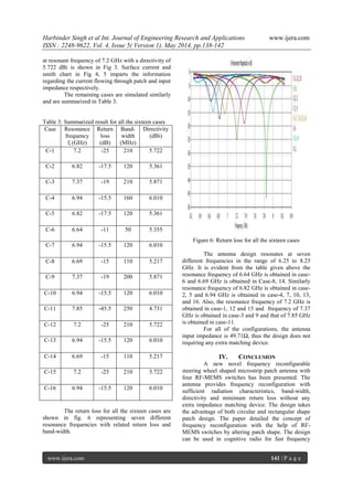
III. RESULT AND DISCUSSIONS
By the implementation of RF-MEMS
switches, one can vary the dimension of radiating
patch and hence the resonating frequencies. The
frequency reconfiguration concept is introduced by
changing the dimensions of the radiating patch,
which further culminates in variation of current and
the resonating frequency. Thus alteration in patch
dimensions strongly controls the resonant modes of
the patch antenna, and this altered patch dimensions
results in a desired operating frequency bands.
In the given antenna design we proposed
four RF-MEMS switches amid rectangular patch and
circular patch. The switches will offer 24
i.e. 16
different configurations as given in Table 2. For
simulation of antenna ideal switching mode of RF-
MEMS switches is considered i.e. in ON state the
switch is replaced by short circuiting a conducting
pin and in OFF state the switch is considered as open
circuit.
Table 2: Different switching configuration of RF-
MEMS switches
Case D1 D2 D3 D4
C-1 OFF OFF OFF OFF
C-2 OFF OFF OFF ON
C-3 OFF OFF ON OFF
C-4 OFF OFF ON ON
C-5 OFF ON OFF OFF
C-6 OFF ON OFF ON
C-7 OFF ON ON OFF
C-8 OFF ON ON ON
C-9 ON OFF OFF OFF
C-10 ON OFF OFF ON
C-11 ON OFF ON OFF
C-12 ON OFF ON ON
C-13 ON ON OFF OFF](https://image.slidesharecdn.com/x4501138142-140716025103-phpapp01/85/X4501138142-2-320.jpg)
![Harbinder Singh et al Int. Journal of Engineering Research and Applications www.ijera.com
ISSN : 2248-9622, Vol. 4, Issue 5( Version 1), May 2014, pp.138-142
www.ijera.com 142 | P a g e
switching in the range of 6.25 to 8.25 GHz, capable
of operating in seven different frequencies.
Future work includes comparison of measured and
simulated result by implementation of RF-MEMS
switches
REFERENCES
[1] B. Wang and K. J. R. Liu, “Advances in
cognitive radio networks: A survey”, IEEE
J. Sel. Topics Signal Process., vol. 5, no. 1,
Feb. 2011, pp. 5–23.
[2] K.-L. Yau, P. Komisarczuk, and P. Teal, “A
context-aware and intelligent dynamic
channel selection scheme for cognitive radio
networks”, 4th International Conference on
Cognitive Radio Oriented Wireless
Networks and Communications, Hannover,
Germany, June 2009, pp. 1 –6.
[3] J.Mitola and G. Q.Maguire, “Cognitive
radio:Making software radios more
personal” ,IEEE Pers. Commun., vol. 6, no.
4, Aug. 1999, pp. 13–18.
[4] P. S. Hall, P. Gardner, and A. Faraone,
“Antenna requirements for software defined
and cognitive radios”, Proc. IEEE, vol. 100,
no. 7, 2012, pp. 2262–2270
[5] Ghanshyam Singh, Mithilesh Kumar,
“Design of Frequency Reconfigurable
Microstrip Patch Antenna”, IEEE 6th
International Conference on Industrial and
Information Systems, Sri Lanka, Aug. 16-19,
2011
[6] Y. Tawk, J. Costantine, C. G.
Christodoulou, “A Rotatable Reconfigurable
Antenna for Cognitive Radio Applications”,
IEEE Transactions on Antennas and
Propagation, 2011
[7] Rahul Agrawal, Girish Awadhwal, M.K.
Meshram, S.P. Singh, “A Novel
Reconfigurable Multiband Patch Antenna”,
IEEE Students Conference on Electrical,
Electronics and Computer Science,2012
[8] N. Ramli, M. T. Ali, A. L. Yusof, S.
Muhamud, “A Frequency Reconfigurable
Stacked Patch Microstrip Antenna
(FRSPMA) using C-Foam in Stacked
Substrate”, IEEE Asia-Pacific Conference
on Applied Electromagnetics (APACE
2012), Melaka, Malaysia, December 11 - 13,
2012.
[9] Hesamedin Joodaki, Hossein Vailee,
Mohammad Bayat, “Reconfigurable Dual
Frequency Microstrip MIMO Patch Antenna
Using RF MEMS Switches for WLAN
Application”, IEEE 25th
Chinese Control
and Decision Conference, 2013
[10] Lei Ge, Kwai-Man Luk, “A Band-
Reconfigurable Antenna Based On Directed
Dipole”, IEEE Transactions on Antennas
and Propagation, Vol. 62, No. 1, January
2014
[11] H. L. Zhu, X. H. Liu, S. W. Cheung, T. I.
Yuk, “Frequency-Reconfigurable Antenna
Using Metasurface”, IEEE Transactions on
Antennas and Propagation, Vol. 62, No. 1,
January 2014
[12] Adam Narbudowicz, Xiulong Bao, Max
Ammann, Hammam Shakhtour, Dirk
Heberling, “Circularly Polarized Antenna
With Steerable Dipole-Like Radiation
Pattern”, IEEE Transactions on Antennas
and Propagation, Vol. 62, No. 2, February
2014
[13] Thomas Apperley, Michal Okoniewski, “An
Air Gap Based Frequency Switching
Method for the Dielectric Resonator
Antenna”, IEEE Antennas and Wireless
Propagation Letters, 2014
[14] Harish Rajagopalan, Joshua M. Kovitz,
Yahya Rahmat-Samii, “MEMS
Reconfigurable Optimized E-Shaped Patch
Antenna Design”, IEEE Transactions on
Antennas and Propagation, Vol. 62, No. 3,
March 2014
[15] Deepali K. Borakhade, S.B.Pokle, “Design
Approach for Frequency Reconfigurable
Vivaldi Antenna with Pentagoan Slot
Resonator”,IEEE International Conference
on Electronic Systems, Signal Processing
and Computing Technologies, 2014
[16] Simone Genovesi, Alessio Di Candia,
Agostino Monorchio, “Compact and Low
Profile Frequency Agile Antenna for Multi
standard Wireless Communication
Systems”, IEEE Transactions on Antennas
and Propagation, Vol. 62, No. 3, March
2014
[17] Lev Pazin, Yehuda Leviatan,
“Reconfigurable Rotated-T Slot Antenna for
Cognitive Radio Systems”, IEEE
Transactions on Antennas and Propagation,
2014
[18] G. M. Rebeiz, RF MEMS: Theory, Design
and Technology. New York, NY, USA:
Wiley, 2003.
[19] I. Kim and Y. Rahmat-Samii, “RF MEMS
Switchable slot patch antenna integrated
with bias network”, IEEE Trans. Antennas
Propag., vol. 59, no. 12, Dec. 2011, pp.
4811–4815.](https://image.slidesharecdn.com/x4501138142-140716025103-phpapp01/85/X4501138142-5-320.jpg)

This paper presents a novel steering wheel shaped frequency reconfigurable microstrip patch antenna designed for cognitive radio systems, capable of operating at seven different frequencies from 6.25 to 8.25 GHz. The antenna employs four RF-MEMS switches to achieve reconfiguration and was simulated using CST Microwave Studio, demonstrating favorable characteristics such as low return loss and good directivity. The results highlight the potential applications of this antenna design in efficient frequency spectrum utilization for cognitive radio technologies.


![Xarxa 29 [castellano]](https://cdn.slidesharecdn.com/ss_thumbnails/xarxa29castellano-120903074845-phpapp01-thumbnail.jpg?width=640&height=640&fit=bounds)


![5G Explained! A High Level Overview [Introduction]](https://cdn.slidesharecdn.com/ss_thumbnails/5gexplainedahighleveloverview-260119165306-cc137a3e-thumbnail.jpg?width=640&height=640&fit=bounds)


