This document proposes variations to a capacitive fed suspended rectangular microstrip antenna (RMSA) configuration to achieve compact broadband and dual-band responses. Initially, a reference antenna is designed with a radiating patch and smaller feed patch above a ground plane. Measured results show an impedance bandwidth of 39%. To achieve broadband response, three slots are cut into the ground plane, extending the bandwidth to 41.9%. To achieve dual-band response, two additional slots are loaded into the radiating patch while keeping the ground plane slots. Measured results validate a dual-band response with 12.65% and 10.29% bandwidths at the lower and upper bands respectively.
![International Journal of Informatics and Communication Technology (IJ-ICT)
Vol.7, No.1, April 2018, pp. 49~56
ISSN: 2252-8776, DOI: 10.11591/ijict.v7i1.pp49-56 49
Journal homepage: http://iaescore.com/journals/index.php/IJICT
Slot Loaded Capacitive fed Suspended RMSA with
Meandered Ground Plane
Ravi M. Yadahalli*1
, Nandini M. Ammanagi2
1
Department of Electronics and Communication Engineering, S.G. Balekundri Institute of Technology, India
2
Department of Electronics and Telecommunication Department, V.E.S. Institute of Technology, India
Article Info ABSTRACT
Article history:
Received jan 26, 2018
Revised Mar 8, 2018
Accepted Mar 15, 2018
In this paper, variations in the capacitive fed suspended RMSA configurations
have been proposed. Initially, the reference antenna consists of rectangular
patch of size of (35.5 X 45.6) mm2
and a small rectangular feed patch of size
of (1.4 X 4) mm2
residing on the same substrate suspended above the ground
plane. Coaxial probe is used to feed the small patch which in turn excites the
radiator patch electromagnetically, yielding a large impedance bandwidth
(BW) of 39%, with good gain and broadside radiation pattern. By, meandering
the ground plane of reference antenna with three rectangular slots, the
prototype antenna is fabricated and measurement has been carried out to
validate the result for compact broadband response. Later, by loading a pair of
rectangular slots in the radiating patch of the reference antenna in addition to
the rectangular slots in the ground plane, the prototype antenna is fabricated
and measurement has been carried out to validate the result for compact dual
band response.
Keyword:
Coupled capacitive feed
Dual band
Electromagnetically
Meandering slots
Rectangular microstrip antenna
(RMSA)
Reference antenna (RA)
Slot loaded
Copyright © 2018 Institute of Advanced Engineering and Science.
All rights reserved.
Corresponding Author:
Ravi M. Yadahalli,
Department of Electronics and Communication Engineering,
S.G. Balekundri Institute of Technology,
Shivabasava Nagar, Belagavi – 590010, Karnataka, India.
Email: yadahalliravim@gmail.com
1. INTRODUCTION
Microstrip Antennas (MSA’s) are popular as it is used in most of the wireless communication systems
offering various advantages. However, the limitation of its narrow bandwidth (BW) restricts its application in
many of the wideband communication systems. Though, there are many approaches [1] to improve the
bandwidth, one of the way is to increase the thickness between the patch and the ground plane.
Probe feed or coaxial feed is popular and widely used in MSA as, it can feed the patch at any arbitrary
position without much difficulty. However, as the height of the substrate increases the inductance associated
with the probe length may lead to unavoidable impedance mismatch. This impedance mismatch can be
compensated by embedding slots in the microstrip patch, changing the shape of probe or by using a novel feed
technique such as capacitive or proximity fed patch [2-3]. A capacitive fed MSA proposed in [2] provides a
wide bandwidth of 50% for C band at 5.9 GHz with RT Duroid substrate (RO3003) having
Ɛr = 3.0 and thickness of 1.56 mm. Also, antenna can be made to resonate at any frequency in L, S, C or X-
band by optimizing the design parameters.
Increase in the bandwidth of MSA due to increase in the height of the substrate or decrease in Ɛr of
the substrate both result in the reduction of the resonant frequency of MSA which in turn reduces the antenna
size. As, reported in [4-5], the meandering technique (embedding slots) in the antenna’s ground plane proved
to be an efficient method of reducing the size and enhancing the bandwidth of MSA. Variations in slots in
radiating patch and ground plane were analysed for compact and broadband operations [6-7]. Dual Frequency](https://image.slidesharecdn.com/8-201019035149/85/8-nan-ijece-edit-sat-1-320.jpg)
![ ISSN: 2252-8776
IJ-ICT Vol. 7, No. 1, April 2018 : 49– 56
50
MSA’s operating at two separate bands for transmit and receive is preferred in all wireless applications
[8-10].
The basic configuration of the proposed antenna is discussed with its design details in Section 2 and
Section 3 provides simulation and experimental validation of the prototype.
2. ANTENNA GEOMETRY
To begin with, Reference Antenna (Capacitive fed RMSA) is designed and optimized to resonate at 2
GHz using FR4 substrate. Later, the ground plane of the RA is meandered using rectangular slots. Further,
along with the meandered ground plane dual rectangular slots are etched in the radiating patch of RA.
The geometry of the reference antenna and the proposed antennas are discussed in detail below.
2.1. Design of Capacitive fed RMSA
The basic geometry of reference antenna (RA), consisting of a rectangular radiating patch of size (L,
W) = (35.5, 45.6) mm, is designed to resonate at fr = 2 GHz for the fundamental TM10mode [1]. The substrate
is positioned on top of the ground plane at a height filled with air as a substrate. Adjacent to the radiating patch,
there is a small rectangular feed patch placed in the same plane. Instead of a direct feed to the MSA, an
electromagnetically coupled capacitive feed is used for improvement in the bandwidth with broadside radiation
characteristics. This feeding mechanism provides compensation for the increased feed inductance.
Figure 1. Geometry of Reference Antenna Configuration
Table1. Typical Dimensions of RA at 2 GHz
Parameter Dimension
Length of the radiating patch ( L ) 35.5 mm
Width of the radiating patch ( W ) 45.6 mm
Feed patch Length ( s ) 4 mm
Feed patch Width ( t ) 1.4 mm
Distance between feed patch & radiating
patch ( d )
1 mm
Air gap between the substrates ( g ) 15 mm
Dielectric constant ( Ɛr) 4.4
Substrate thickness ( h ) 1.6 mm
The basic principle underlying the operation of the reference antenna is capacitive coupling between
the driven patch and the radiating patch. The gap introduces a capacitance into the feed, so that it can cancel
out the inductance added by the probe feed. Figure 1 shows the geometry of the prototype wherein a larger
patch works as radiator and the smaller one acts as a feed patch using which radiator is excited by capacitive
means. Coaxial probe feed is positioned at the center of the feed patch to excite it. A finite ground plane with](https://image.slidesharecdn.com/8-201019035149/85/8-nan-ijece-edit-sat-2-320.jpg)
![IJ-ICT ISSN: 2252-8776
Slot Loaded Capacitive fed Suspended RMSA with Maender Ground Plane (Ravi M. Yadahalli)
51
size 75x75 mm2
is used in the design. The radiating patch and feed patch used for the RA are both
rectangular in shape.
The design parameters of the RA are listed in Table 1. By optimizing the dimensions of the feed patch
(t & s), distance (d) between the feed patch and the radiator patch and air gap distance (g) between the substrate
and the ground plane, Impedance bandwidth of RA can be significantly increased to 39%. The air gap distance
[2] given by,
g≈=0.16 λc–h√Ɛr (1)
Where λc is the wavelength corresponding to the centre frequency of the operational band, h is the
height of the substrate and Ɛr is dielectric constant of the substrate.
This is because, by adding air between radiating patch and the ground plane the effective dielectric
constant below the patch reduces, thus increasing the bandwidth and efficiency of the antenna [11]. Optimizing
the air gap distance ‘g’ is very important design parameter, as it is responsible for merging the two close
resonance frequencies into a single operational band below -10dB return loss. A slight shift in the resonant
frequency is also observed. This is due to the fact that as air gap increases, the effective dielectric constant
changes leading to a change in effective width and length of the patch. The distance (d) between the radiating
patch and the feed patch have a very small effect on the bandwidth although it affects the impedance matching.
The impedance bandwidth of the antenna slightly decreases with an increase in the feed patch width (t),
provided other parameters are kept constant, but the bandwidth loss can be recovered to its actual value by
decreasing the length of feed patch [12]. Considering an improvised bandwidth, impedance matching and
broadside radiation characteristics, the various parameters such as s, t, d, g are optimized for the RA and are
shown in Table 1.
2.2. Design of Capacitive fed RMSA with Meandered Ground Plane
Three rectangular slots of same length (~λ0/4) and width (~λ0/100) operating at a frequency of 2 GHz
are cut in the ground plane of the RA. The slots are aligned side by side with an equal spacing of L/4 from each
other as shown in Figure 2. The width of slot is 1mm. The length of the slot is (Li +Lo), where Li is the slot
length inside the projected image of radiator patch in ground plane and Lo is the length of slot outside the
projected image of radiator patch in ground plane [4-5]. Coaxial probe is used to excite the feed patch at the
centre which in turn excites the radiating patch.
Figure 2. Geometry of Proposed Antenna Configuration I](https://image.slidesharecdn.com/8-201019035149/85/8-nan-ijece-edit-sat-3-320.jpg)
![ ISSN: 2252-8776
IJ-ICT Vol. 7, No. 1, April 2018 : 49– 56
52
2.3. Design of Slot Loaded Capacitive fed RMSA with Meandered Ground Plane
In addition to the geometry shown in Figure 2 Dual rectangular slots of same length and width are
loaded at the non- radiating edges of the radiating patch of the RA. The slots lie very close and run along the
radiating edges of the radiating patch as shown in Figure 3 The length of the slot Ls=44.6mm (~λ0/2) and width
Ws=1mm (~λ0/100) operating at 2 GHz.
Figure 3.Geometry of Proposed Antenna Configuration II
3. EXPERIMENTAL RESULTS AND DISCUSSION
The characteristics of the RA and the proposed antennas are investigated by using MOM based
electromagnetic solver Hyperlynx 3D EM Software [13]. The proposed antennas are fabricated using FR4
substrate (with dielectric constant 4.4, loss tangent 0.02, thickness 1.6mm). The simulation results are validated
using Rohde & Schwarz ZVH-8 Vector Network Analyzer.
3.1. Experimental Results of Capacitive fed RMSA
The reference antenna with the proposed geometry as shown in Figure 1. having dimensions
listed in Table 1). The pin of SMA connector is extended by using a copper wire to excite the feed patch
through the air gap.
Figure 4. |S11| Characteristics of Reference Antenna](https://image.slidesharecdn.com/8-201019035149/85/8-nan-ijece-edit-sat-4-320.jpg)
![IJ-ICT ISSN: 2252-8776
Slot Loaded Capacitive fed Suspended RMSA with Maender Ground Plane (Ravi M. Yadahalli)
53
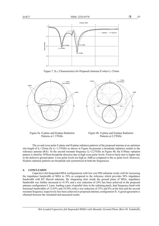
Figure 5a. E-plane and H-plane Radiation
Pattern at 2GHz
Figure 5b. E-plane and H-plane Radiation
Pattern at 2.5GHz
Figure 5c. E-plane and H-Plane Radiation
Pattern at 2.89GHz
Figure 5d.Variation of Gain Vs
Frequency Characteristics
Figure 4 shows the |S11|characteristics of Reference Antenna. For RA, fundamental resonant mode
TM10 is excited at 2.42 GHz with 10dB return loss. The measured return loss (S11) is much below -10dB
(VSWR < 2) corresponding to a frequency range of (1.94-2.89) GHz providing aimpedance bandwidth of
950MHz (39%). The simulated and measured results are in close agreement with each other.
The co and cross polarized E-plane and H-plane radiation patterns of prototype at selected frequencies
within the operational band are shown in the Figure 5a, Figure 5b, and Figure 5c for frequencies at 2GHz,
2.5GHz and 2.89GHz respectively. H-plane radiation patterns are broadside and symmetrical at all frequencies,
however there is small asymmetry in E-plane radiation patterns especially at high frequencies due to
asymmetrical feed arrangement. As, the total substrate thickness increases, the probe length increases, thus the
feed patch acts as a top loaded monopole antenna which radiates and is responsible for the high cross polar
levels. The gain versus frequency plot as shown in Figure 5d shows a peak gain of 7.07dBi at 2.5GHz with
gain reducing at higher frequencies due to an increase in cross polar levels.
3.2. Experimental Results of Capacitive fed RMSA with Meandered Ground Plane
For the Proposed Antenna I shown in Figure 2, the slot length Lo for the prototype is fixed to be at 10
mm [4, 5]. A parametric study is carried out by varying the slot length Li from 0 to 35mm, keeping Lo fixed at
10mm and their width’s Ws constant at 1mm. The effect of varying the slot length Li on parameters such as
resonant frequency and impedance bandwidth of the proposed antenna is studied. As the slot length Li increases](https://image.slidesharecdn.com/8-201019035149/85/8-nan-ijece-edit-sat-5-320.jpg)
![ ISSN: 2252-8776
IJ-ICT Vol. 7, No. 1, April 2018 : 49– 56
54
from 0mm to 35mm (~λ0/4), lowering in the resonant frequency and increase in the impedance bandwidth is
observed. The resonant frequency decreases due to the path length of the surface current around the slots. The
meandering technique (embedding slots) in the ground plane of antenna effectively reduces the quality factor
of the proposed antenna and accounts for enhanced bandwidth.
In case of slot length (Li=35 mm & Lo=10mm), the resonant frequency is lowered to 1.8GHz i.e. the
resonant frequency is approximately 0.76 times that of RA giving a size reduction of about 23%.
Figure 6. |S11| Characteristics for Proposed Antenna I when Li=35mm
To further validate the results, the simulated and measured S11 characteristics are shown in Figure 6.
The measured return loss is much below -10dB (VSWR < 2) corresponding to a range of frequencies (1.49-
2.28) GHz, providing animpedance bandwidth of 41.9% at the optimized slot length. The simulated and
measured results are in reasonable agreement with each other. Front to back ratio and the backward radiation
increases due to the embedded slots in the ground plane resulting in bi-directional radiation patterns in both
E and H planes.
3.3. Experimental Results of Slot Loaded Capacitive fed RMSA with Meandered Ground Plane
For the Proposed Antenna Configuration II shown in Figure 3, dual rectangular slots are loaded in the
radiating patch having length Ls=44.6mm and width Ws=1mm [7]. A parametric study is carried out by varying
the slot length Li (length inside the projected image of radiator patch) from 0 to 35mm keeping Ls at 44.6mm
and width Ws at1mm. The effect of varying the slot length Li on parameters such as resonant frequency and
impedance bandwidth of the proposed antenna is studied.
As the slot length Li increases from 0mm to 35mm, lowering in both the resonant frequencies is
observed. In case of slot length (Li=35 mm & Lo=10mm), the first resonant frequency (fr1) is reduced to
1.56GHz which is about 0.64 times that of RA, giving a size reduction of 35% and second resonance (fr2) is
reduced to 2.2GHz which is about 0.92 times that of RA, giving a size reduction of 8%. The proposed antenna
does not provide any higher order resonant frequency if the slot length is further increased. At this optimal slot
length, there is a significant reduction in size and bandwidth of the proposed antenna with frequency ratio
(fr2/fr1) of 1.42 resulting in a compact dual band characteristic. Results clearly indicate that, fr1 has a bandwidth
of 12.65% and fr2 has a bandwidth of 10.29%.
To further validate the results, |S11| characteristics are shown in Figure 7. The simulated and measured
results are in close agreement with each other.](https://image.slidesharecdn.com/8-201019035149/85/8-nan-ijece-edit-sat-6-320.jpg)
![ ISSN: 2252-8776
IJ-ICT Vol. 7, No. 1, April 2018 : 49– 56
56
REFERENCES
[1] G. Kumar, K.P. Ray. “Broadband Microstrip Antennas”, Artech House, Norwood, Mass, USA, 2001.
[2] Veeresh G. Kasbegoudar, Dibyant S. Upadhyay, K. J. Vinoy. Research Article “Design Studies of Ultra-Wideband
Microstrip Antennas with a Small Capacitive Feed”, Hindawi Publishing Corporation. International Journal of
antennas and Propagation, Volume 2007, Article ID 67503, 8 pages doi:10.1155/2007/67503.
[3] Amit A. Deshmukh. “Broadband proximity fed ring microstrip antenna arrays”, AEU - International Journal of
Electronics and Communications, 2014; 68(8) August: 710-716.
[4] K.L. Wong. “Compact and Broadband microstrip antennas”, Wiley, New York, 2002.
[5] Jieh-SenKuo, Kin-Lu Wong. “A Compact Microstrip Antenna with meandering slots in the Ground Plane”,
Microwave and Optical technology Letter , 2001; 29(2) April: 95-97.
[6] UshaKiran, Vani R. M. , Ravi M. Yadahalli, P. V. Hunagund, and Sara F. Farida “Microstrip-Line-Fed Rectangular
Microstrip Antenna with Open end Meandering slots in the ground plane for compact broadband operation”,
Microwave and Optical Technology Letters, 2007; 49(4) April: 824-827.
[7] UshaKiran, R.M. Yadahalli, Vani R.M., Sara F Farida, P.V. Hunagund. “Compact Broadband Dual frequency slot
loaded rectangular microstrip antenna with ground plane meandering slots and stacking”, Microwave and Optical
Technology Letters, 2007; 49(10) October: 2477-2481.
[8] S.S. Zhong, Y.T. Lo. ”Single element rectangular microstrip antenna for dual frequency operation”, Electronic
Letters, 14th April, 1983: 19(8): 298-300.
[9] S.C. Gao, L.W. Li. T.S. Yeo, M.S. Leong. “A dual-frequency compact microstrip patch antenna”, Radio Science,
2001; 36(November-December): 1669-1682.
[10] S. Maci, G. BiffiGentilli, P. Plazzesi, C. Salvador. “Dual band slot loaded patch antenna”, IEEE Proc.- Microw,
Antennas Propagation, 1995; 142(3) June: 225-232.
[11] ChoonSae Lee, VahaknNalbandian. “Impedance matching of a dual frequency microstrip antenna with an airgap”,
IEEE Transactions on Antennas and Propagation, 1993; 41(5) May: 680-682.
[12] Veeresh G. Kasbegoudar, K. J. Vinoy. “Coplanar Capacitively coupled probe fed Microstrip antennas for Wideband
applications”, IEEE Transactions on Antennas and Propagation, 2010; 58(10) October: 3131-3138.
[13] Hyperlynx3D EM Software from Mentor Graphics (formerly called IE3D).](https://image.slidesharecdn.com/8-201019035149/85/8-nan-ijece-edit-sat-8-320.jpg)


![5G Explained! A High Level Overview [Introduction]](https://cdn.slidesharecdn.com/ss_thumbnails/5gexplainedahighleveloverview-260119165306-cc137a3e-thumbnail.jpg?width=640&height=640&fit=bounds)


