The document discusses the design and performance of a truncated corner square patch antenna optimized for WLAN applications, achieving circular polarization at 5.8 GHz and 9.2 GHz. The antenna is built on an FR4 substrate and demonstrates a peak gain of 7.5 dB and 6.4 dB at the respective frequencies. Results indicate good impedance matching, high efficiency, and the potential for application in body-centric communication systems.
![International Journal of Innovative Technology and Exploring Engineering (IJITEE)
ISSN: 2278-3075, Volume-8 Issue-8 June, 2019
1328
Published By:
Blue Eyes Intelligence Engineering
& Sciences Publication
Retrieval Number: H7516068819/19©BEIESP
Abstract: An antenna having a square radiating aperture named
as patch is truncated at its opposite corners and power excitation
is applied through its edge. This structure is best suitable for
WLAN applications. Because of truncation the distribution of
current over the patch is controlled and improves the axial ratio
of the antenna, hence achieves circular polarization at two
operating frequencies which are of 5.8 GHz and 9.2 GHz
respectively. To validate the simulated results, prototype of
proposed structure is done on FR4 substrate with a relative
permittivity of 4.4 and thickness of 1.6 mm. Current design
producing a peak realized gain of 7.5 dB at 5.8 GHz and 6.4 dB at
9.2 GHz. The complete structure was designed and simulated for
results at CST microwave studio-based Antenna Magus tool and
the measured results are analyzed with aniritsu combinational
analyzer in anechoic chamber.
Index Terms: Circular Polarization (CP), Axial Ratio (AR),
Edge-Fed, WLAN.
I. INTRODUCTION
The Microstrip Patch Antenna (MPA) is the most
popularly used antenna for wireless communication
applications. The MPAs commonlywork about the half-wave
resonance frequency to obtain nominally real-valued input
impedance. The fringing fields of MPA virtually increases its
effective length, so in real, the patch length is less than a half
wavelength in the dielectric medium. MPAs are
uncomplicated and reasonably priced to manufacture, and
can fabricate using modern printed-circuit technology[1-6].
In generally radiating aperture of MPA designed, so that
its maximum radiating pattern is normal to radiating
aperture of patch, this is achieved by appropriately selecting
the mode of excitation underneath the patch [7-9]. For a
MPA, the length of the element is usuallybetween a third and
half a wavelength in the substrate. Numerous authors
presented in literature that by varying the feed arrangements
one can achieve Circular and elliptical polarization. Another
method proposed were suggesting that slender modifications
made on the radiating aperture of antenna element, can
produce two orthogonal modes with equal amplitudes and
90° time-phase difference. For instance, truncating any two
opposite corners of square patch, can achieve quadrature
phase coupling between the orthogonal TM01 and TM10
Revised Manuscript Received on June 7, 2019
Dr. Praveen Kumar Kancherla, Associate Professor, Dept of ECE, CMRIT
cavity modes and hence nearly circular polarization may
be achieved.
Currently the antennas are flattering an essential part of
body-centric communication systems and have latent
applications for example health monitoring, surveillance and
emergency services etc. These systems usually require wide
band antennas with compact in size; with multiple
application frequencies this is possible through the rising
technologies [10-12].
The printed monopole antenna design (both radiating
patch and corresponding ground) is more flexible. To meet
the given specifications, the overall structure of antenna need
more optimization, this is ever a challenging task to antenna
engineers [13-18]. Modern communication systems are
demanding multifunctional devices, means a single system
or element need to perform multiple numbers of tasks, for
example single antenna with multiple operating frequencies
and pattern selectivity. To achieve so, multiband and
wideband antennas with high bandwidth and considerable
gain [19-22] and High-speed data rates.
II. ANTENNA GEOMETRY
The MPA proposed in this article, consists of a square
shaped patch element with 50 ohm impedance matching at
the feed line via power divider arrangement. The complete
antenna design is presented in below Fig 1. Corresponding
antenna side view is depicted in Fig 2. The description of
dimensional parameters and its design values are tabulated
and given in Table 1.
Fig 1. Model of Edge feed square MPA, truncated at its
opposite corners to produce circular polarization.
Circularly Polarization of Edge-Fed Square
Patch Antenna using Truncated Technique for
WLAN Applications
Praveen Kumar Kancherla](https://image.slidesharecdn.com/paper12019-220304085211/85/Paper-1-2019-1-320.jpg)
![International Journal of Innovative Technology and Exploring Engineering (IJITEE)
ISSN: 2278-3075, Volume-8 Issue-8 June, 2019
1328
Published By:
Blue Eyes Intelligence Engineering
& Sciences Publication
Retrieval Number: H7516068819/19©BEIESP
Abstract: An antenna having a square radiating aperture named
as patch is truncated at its opposite corners and power excitation
is applied through its edge. This structure is best suitable for
WLAN applications. Because of truncation the distribution of
current over the patch is controlled and improves the axial ratio
of the antenna, hence achieves circular polarization at two
operating frequencies which are of 5.8 GHz and 9.2 GHz
respectively. To validate the simulated results, prototype of
proposed structure is done on FR4 substrate with a relative
permittivity of 4.4 and thickness of 1.6 mm. Current design
producing a peak realized gain of 7.5 dB at 5.8 GHz and 6.4 dB at
9.2 GHz. The complete structure was designed and simulated for
results at CST microwave studio-based Antenna Magus tool and
the measured results are analyzed with aniritsu combinational
analyzer in anechoic chamber.
Index Terms: Circular Polarization (CP), Axial Ratio (AR),
Edge-Fed, WLAN.
I. INTRODUCTION
The Microstrip Patch Antenna (MPA) is the most
popularly used antenna for wireless communication
applications. The MPAs commonlywork about the half-wave
resonance frequency to obtain nominally real-valued input
impedance. The fringing fields of MPA virtually increases its
effective length, so in real, the patch length is less than a half
wavelength in the dielectric medium. MPAs are
uncomplicated and reasonably priced to manufacture, and
can fabricate using modern printed-circuit technology[1-6].
In generally radiating aperture of MPA designed, so that
its maximum radiating pattern is normal to radiating
aperture of patch, this is achieved by appropriately selecting
the mode of excitation underneath the patch [7-9]. For a
MPA, the length of the element is usuallybetween a third and
half a wavelength in the substrate. Numerous authors
presented in literature that by varying the feed arrangements
one can achieve Circular and elliptical polarization. Another
method proposed were suggesting that slender modifications
made on the radiating aperture of antenna element, can
produce two orthogonal modes with equal amplitudes and
90° time-phase difference. For instance, truncating any two
opposite corners of square patch, can achieve quadrature
phase coupling between the orthogonal TM01 and TM10
Revised Manuscript Received on June 7, 2019
Dr. Praveen Kumar Kancherla, Associate Professor, Dept of ECE, CMRIT
cavity modes and hence nearly circular polarization may
be achieved.
Currently the antennas are flattering an essential part of
body-centric communication systems and have latent
applications for example health monitoring, surveillance and
emergency services etc. These systems usually require wide
band antennas with compact in size; with multiple
application frequencies this is possible through the rising
technologies [10-12].
The printed monopole antenna design (both radiating
patch and corresponding ground) is more flexible. To meet
the given specifications, the overall structure of antenna need
more optimization, this is ever a challenging task to antenna
engineers [13-18]. Modern communication systems are
demanding multifunctional devices, means a single system
or element need to perform multiple numbers of tasks, for
example single antenna with multiple operating frequencies
and pattern selectivity. To achieve so, multiband and
wideband antennas with high bandwidth and considerable
gain [19-22] and High-speed data rates.
II. ANTENNA GEOMETRY
The MPA proposed in this article, consists of a square
shaped patch element with 50 ohm impedance matching at
the feed line via power divider arrangement. The complete
antenna design is presented in below Fig 1. Corresponding
antenna side view is depicted in Fig 2. The description of
dimensional parameters and its design values are tabulated
and given in Table 1.
Fig 1. Model of Edge feed square MPA, truncated at its
opposite corners to produce circular polarization.
Circularly Polarization of Edge-Fed Square
Patch Antenna using Truncated Technique for
WLAN Applications
Praveen Kumar Kancherla](https://image.slidesharecdn.com/paper12019-220304085211/75/Paper-1-2019-1-2048.jpg)
![Circularly Polarization of Edge-Fed Square Patch Antenna using Truncated Technique for WLAN
Applications
1329
Published By:
Blue Eyes Intelligence Engineering
& Sciences Publication
Retrieval Number: H7516068819/19©BEIESP
Fig 2. Side view of Edge feed square MPA, truncated at
its opposite corners, placed over FR4 substrate backed by
conducting ground.
Table 1. Description of Antenna parameters and its
corresponding values.
S.
No
Parameter Description Value
1 W Width of Patch 17.61
mm
2 Lt extent of
Truncation
2.065
mm
3 Wm Matching
width of line
535.2
μm
4 Lm Matching
length line
10.22
mm
5 Wf Feed width of
line
1.066
mm
6 Lf Feed length of
line
10.10
mm
7 H Thickness of
Substrate
1.096
mm
8 εr Relative
permittivity
2.2
9 tanδ Substrate’s
Loss tangent
0.002
Ⅲ. ANALYSIS OF RESULTS THROUGH
DISCUSSION
In general, MPA exhibits forward broadside gain of
typically 7 dBi at its resonating frequency, but due to
truncation method or other polarization techniques proposed
in literature may affect the performance in bandwidth by
reducing it and hence the performance of AR.
Fig 3. Impedance characteristics of truncated square
MPA at two operating points that is 5.2GHz and 9.2GHz.
In current design, truncated edge feed square MPA is
operating at 5.2GHz and 9.2GHz frequencies. Usually
antenna impedance can be defined by its real value of
resistance and imaginary value of reactance. Fig 3. Clearly
showing the real value (indicated with continuous line) and
reactance (indicated with discrete line) which are very much
nearer to 50 ohms at both the operating points (that is
5.2GHz, 9.2GHz), this indicates at both the operating points
the antenna is perfectly matched with its source through feed
line. From Fig. 4, it can be observed that the return loss
(magnitude of S11) is less than -10 dB at both the resonance
bands. The impedance bandwidths of 34% and 21% are
obtained at 5.8 GHz, and 9.2 GHz frequencies respectively.
Fig 4. Return loss characteristics of edge feed truncated
square MPA, operating at dual frequencies.
Fig 5. VSWR characteristics of edge feed truncated
square MPA, operating at dual frequencies.
The amount of power, which is reflected back to source from
the antenna due to impedance mismatch at feeding point, can
be explained byusing VSWR value. In current design VSWR
ratio is 2:1, indicating that the designed antenna is at most
perfectly matched. ratio. With the help of obtained VSWR
value antenna reflection coefficient can be determined using
following formula. Reflection coefficient = -10 log
[(VSWR-1)/VSWR+1)2
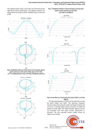
] –(1) Fig 6, is depicting the
radiation characteristics of truncated square patch antenna. It
is radiating maximum of its energy in forward direction. For
better under understanding of obtained results they are
presented in 2D view as well as in polar coordinates.](https://image.slidesharecdn.com/paper12019-220304085211/85/Paper-1-2019-2-320.jpg)
![Circularly Polarization of Edge-Fed Square Patch Antenna using Truncated Technique for WLAN
Applications
1331
Published By:
Blue Eyes Intelligence Engineering
& Sciences Publication
Retrieval Number: H7516068819/19©BEIESP
The position of the truncations will change the handedness
of the antenna between LHC and RHC. Height of substrate
material influences the axial ratio of an antenna, when height
of substrate increases axial ratio will be poor.
Fig 9 and 10 showing the obtained axial ratios of proposed
design, presented in 2D and 3D plots.
Fig 9. Axial Ratio Vs Frequency
(a) (b)
(c)
Fig 10. 3D-Gain Plots, (a) Total Gain, (b) LHCP Gain, (c)
RHCP Gain
In order to make wireless communication modules more
efficient and accurate, it is very much necessary to have good
correlation between modules. For instance, to minimize the
losses in any communication module, it is very much
importance to have high degree correlation between a
transmitted signal and received signal. To determine the
transmission characteristics of proposed edge feed truncated
square patch antenna, considered transmitting and receiving
antennas arranged one to one face with a distance of 50cm
apart. The transmitted and received signals are indicated s(t)
and r(t) respectively. The correlation between transmitted
and received signals can determine using following formula.
2 2
( ) ( )
( ) ( )
S t r t dt
F Max
S t dt r t dt
--- [ 2]
Fig. 11 showing the time domain analysis of received
signal in comparison with transmission signal. Here the
received signal amplitude and shape are changing. In this
study, fundamental pulses are considered for both
transmission and the reception cases; The response of
antenna is very quick even for a small change in the input
signal.
Fig 11. Comparative study of transmitted and received
pulses in Time domain.
Fig 12. Frequency Vs Efficiency
The efficiency of antenna is another parameter, through
which obtained results can be validated much effectively.
From, Fig 12. It is evident that the total efficiency is high at
the resonant frequency 5.8 GHz and constant at remaining
frequency range.](https://image.slidesharecdn.com/paper12019-220304085211/85/Paper-1-2019-4-320.jpg)
![International Journal of Innovative Technology and Exploring Engineering (IJITEE)
ISSN: 2278-3075, Volume-8 Issue-8 June, 2019
1332
Published By:
Blue Eyes Intelligence Engineering
& Sciences Publication
Retrieval Number: H7516068819/19©BEIESP
Ref No Size in mm Operating
Bands GHz
Gain
in dB
[3] 46X42X1.6 Single
Band
3.45
[6] 48X44X1.6 Dual Band 4.32
[8] 54X48X1.6 Triple
Band
3.65
[11] 56X52X1.6 Dual Band 4.86
[15] 45X40X1.6 Single
Band
5.28
Proposed
Antenna
32X17.6X1.6 Dual Band 7.56
IV CONCLUSION
Current design of circularly polarized antenna is
most suitable for wireless communication applications is
designed to operate at two centre frequencies (i.e 5.8GHz,
9.2GHz) with impedance bandwidth of 34% and 21% and
presented. The dimensions of radiating aperture antenna are
32X17.6 square mm on FR4 substrate of height 1.6 mm. By
truncating technique, the axial ratio of antenna is improved
hence forth circular polarization is achieved, by controlled
the current distribution over the antenna aperture.
REFERENCES
1. K Sai ram, M Deepika, V Naresh, “Circularly Polarized Koch Fractal
Triband Antenna for Communication Applications” ARPN Journal of
Engineering and Applied Sciences, Vol 10, No 14, Aug-15, pp
5795-5801.
2. K Phani Srinivas, Novel Koch fractal circularly polarized micro strip
antenna for global positioning system application, Leonardo Electronic
Journal of Practices and Technologies, Vol 27, Issue 2, December 2015,
pp 31-40.
3. Habibulla Khan, Sarat K. Kotamraju, Circularly Polarized Slotted
Aperture Antenna with Coplanar Waveguide Fed for Broadband
Applications, Journal of Engineering Science and Technology, Vol. 11,
No. 2, Feb-2016, pp 267 – 277.
4. V. Sai Krishna, P. Pardhasaradhi, High Bandwidth Circularly Polarized
X-Slot Antenna, Far East Journal of Electronics and Communications,
Volume 16, Number 3, Aug 2016, Pages 561-572.
5. Y. S. V. Raman, Analysis of Circularly Polarized Notch Band Antenna
With DGS, ARPN Journal of Engineering and Applied Sciences, Vol. 11,
No. 17, September 2016.
6. Abdul Rahiman Sheik, Kalva Sri Rama Krishna, Circularly Polarized
Defected Ground Broadband Antennas for Wireless Communication
Applications, Lecture Notes in Electrical Engineering, ISSN: 1876-1100,
Vol 434, 2017, pp 419-427.
7. P. Poorna Priya, Habibulla Khan, Defected Ground Structure Circularly
Polarized Wideband Antennas for Wireless Communication
Applications, Journal of Advanced Research in Dynamical and Control
Systems, Vol 9, No 18, 2017, pp 122-130.
8. T V Rama Krishna, D Amulya, T Anil Kumar, Design of Cpw fed
F-shaped circularly polarized antenna for amateur radio vehicular
communications, International Journal of Engineering and Technology,
Vol 7, Issue 1.1, 2018, pp 360-365.
9. Habibulla Khan, M Venkateswara Rao, X-Slotted Circularly Polarized
Antenna with Parasitic Patches, International Journal of Engineering and
Technology, Vol 7, Issue 1.1, 2018, pp 534-538.
10. Venkateswara Rao M, B T P Madhav, Anil Kumar T, Prudhvi Nadh B,
Metamaterial inspired quad band circularly polarized antenna for
WLAN/ISM/Bluetooth/WiMAX and satellite communication
applications, AEU - International Journal of Electronics and
Communications, Vol 97, 2018, pp 229-241.
11. N V Seshagiri Rao, Kumari Y, M Ajay Babu, Design and analysis of
printed dual band planar inverted folded flat antenna for laptop devices,
Far East Journal of Electronics and Communications, Vol 16, No 1,
Jan-2016, pp 81-88.
12. Badugu P. Nadh, B T P Madhav, Munuswamy S. Kumar, Manikonda V.
Rao, Tirunagari Anilkumar, Asymmetric Ground Structured Circularly
Polarized Antenna for ISM and WLAN Band Applications, Progress in
Electromagnetics Research M, Vol. 76, 2018, Pp 167–175.
13. D S Ramkiran, Kankara Narasimha Reddy, Shaik Shabbeer, Priyanshi
Jain, Saggurthi Sowmya, Coplanar Wave Guide Fed Dual Band Notched
MIMO Antenna, International Journal of Electrical and Computer
Engineering, Vol. 6, No. 4, August 2016, pp. 1732-1741
14. Asa Jyothi, M. Deepthi, C. Sindhoora, V. Jayanth, A Novel Compact
CPW- Fed Polarization Diversity Dual Band Antenna using H-Shaped
Slots, Indian Journal of Science and Technology, Vol 9, Issue 37, 2016,
pp 1-8.
15. Prakash B L, Sai Parimala B, Sravya T, Anil Kumar T, Dual Band Notch
MIMO antenna with meander slot and DGS for ultra-wideband
applications, ARPN Journal of Engineering and Applied Sciences, Vol
12, Issue 15, 2017, pp 4494-4501.
16. K S R Murthy, K Umakantham, K S N Murthy, Polarization and
Frequency Reconfigurable Antenna for Dual Band ISM Medical and
Wi-Fi Applications, International Journal of Engineering and
Technology, Vol 7, No 3.27, 2018, pp 651-654.
17. A Manikanta Prasanth, Sreeramineni Prasanth, Batchu Mohan Sai
Krishna, Devani Manikantha, Usirika Sharmila NagaSai, Analysis of
Defected Ground Structure Notched Monopole Antenna, ARPN Journal
of Engineering and Applied Sciences, Vol. 10, No. 2, 2015, pp 747-752.
18. Krishnam Naidu Yedla, G.S., Kumar, K.V.V., Rahul, R., , Fractal
aperture EBG ground structured dual band planar slot antenna,
International Journal of Applied Engineering Research, ISSN
0973-4562, Volume 9, Number 5, Jan-2014, pp 515-524.
19. S. S. Mohan Reddy, Bandi Sanjay, D. Ujwala, Trident Shaped Ultra
Wideband Antenna Analysis based on Substrate Permittivity,
International Journal of Applied Engineering Research, ISSN
0973-4562, Vol 8, No 12, 2013, pp. 1355-1361.
20. Mounika Sanikommu, M. N. V. S. Pranoop, K. S. N. Manikanta Chandra
Bose and B. Sriram Kumar, CPW Fed Antenna for Wideband
Applications based on Tapered Step Ground and EBG Structure, Indian
Journal of Science and Technology, Vol 8, Issue 9, 2015, pp 119-127.
21. VGKM Pisipati1, Habibulla Khan, V.G.N. S Prasad, K. Praveen Kumar,
KVL Bhavani and M. Ravi Kumar, Liquid Crystal Bow-Tie Microstrip
antenna for Wireless Communication Applications, Journal of
Engineering Science and Technology Review, Vol 4, No 2, 2011, pp
131-134.
22.D S Ram Kiran, Novel compact asymmetrical fractal aperture Notch band
antenna, Leonardo Electronic Journal of Practices and Technologies, Vol
27, Issue 2, 2015, pp 1-12.](https://image.slidesharecdn.com/paper12019-220304085211/85/Paper-1-2019-5-320.jpg)


