Download to read offline
![10/25/2020 Wormhole switching - Wikipedia
https://en.wikipedia.org/wiki/Wormhole_switching 1/5
Wormhole switching
Wormhole flow control, also called wormhole switching or wormhole routing, is a system
of simple flow control in computer networking based on known fixed links. It is a subset of flow
control methods called Flit-Buffer Flow Control.[1]:Chapter 13.2.1
Switching is a more appropriate term than routing, as "routing" defines the route or path taken to
reach the destination.[2][3] The wormhole technique does not dictate the route to the destination but
decides when the packet moves forward from a router.
Wormhole switching is widely used in multicomputers because of its low latency and small
requirements at the nodes.[3]:376
Wormhole routing supports very low-latency, high-speed, guaranteed delivery of packets suitable for
real-time communication.[4]
Mechanism principle
Example
Advantages
Usage
Virtual channels
Routing
Source routing
Logical routing
See also
References
In the wormhole flow control, each packet is broken into small pieces called flits (flow control units).
Commonly, the first flits, called the header flits, holds information about this packet's route (for
example, the destination address) and sets up the routing behavior for all subsequent flits associated
with the packet. The header flits are followed by zero or more body flits which contain the actual
payload of data. Some final flits, called the tail flits, perform some bookkeeping to close the
connection between the two nodes.
In wormhole switching, each buffer is either idle, or allocated to one packet. A header flit can be
forwarded to a buffer if this buffer is idle. This allocates the buffer to the packet. A body or trailer flit
can be forwarded to a buffer if this buffer is allocated to its packet and is not full. The last flit frees the
buffer. If the header flit is blocked in the network, the buffer fills up, and once full, no more flits can
be sent: this effect is called "back-pressure" and can be propagated back to the source.
Contents
Mechanism principle](https://image.slidesharecdn.com/wormholeswitching-wikipedia-201025165923/85/Wormhole-switching-Notes-1-320.jpg)
![10/25/2020 Wormhole switching - Wikipedia
https://en.wikipedia.org/wiki/Wormhole_switching 1/5
Wormhole switching
Wormhole flow control, also called wormhole switching or wormhole routing, is a system
of simple flow control in computer networking based on known fixed links. It is a subset of flow
control methods called Flit-Buffer Flow Control.[1]:Chapter 13.2.1
Switching is a more appropriate term than routing, as "routing" defines the route or path taken to
reach the destination.[2][3] The wormhole technique does not dictate the route to the destination but
decides when the packet moves forward from a router.
Wormhole switching is widely used in multicomputers because of its low latency and small
requirements at the nodes.[3]:376
Wormhole routing supports very low-latency, high-speed, guaranteed delivery of packets suitable for
real-time communication.[4]
Mechanism principle
Example
Advantages
Usage
Virtual channels
Routing
Source routing
Logical routing
See also
References
In the wormhole flow control, each packet is broken into small pieces called flits (flow control units).
Commonly, the first flits, called the header flits, holds information about this packet's route (for
example, the destination address) and sets up the routing behavior for all subsequent flits associated
with the packet. The header flits are followed by zero or more body flits which contain the actual
payload of data. Some final flits, called the tail flits, perform some bookkeeping to close the
connection between the two nodes.
In wormhole switching, each buffer is either idle, or allocated to one packet. A header flit can be
forwarded to a buffer if this buffer is idle. This allocates the buffer to the packet. A body or trailer flit
can be forwarded to a buffer if this buffer is allocated to its packet and is not full. The last flit frees the
buffer. If the header flit is blocked in the network, the buffer fills up, and once full, no more flits can
be sent: this effect is called "back-pressure" and can be propagated back to the source.
Contents
Mechanism principle](https://image.slidesharecdn.com/wormholeswitching-wikipedia-201025165923/75/Wormhole-switching-Notes-1-2048.jpg)
![10/25/2020 Wormhole switching - Wikipedia
https://en.wikipedia.org/wiki/Wormhole_switching 2/5
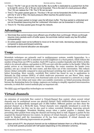
Three flows on 2x2 network using Wormhole switching
The name "wormhole" plays on the way packets are sent over the links: the address is so short that it
can be translated before the message itself arrives. This allows the router to quickly set up the routing
of the actual message and then "bow out" of the rest of the conversation. Since a packet is transmitted
flit by flit, it may occupy several flit buffers along its path, creating a worm-like image.
This behaviour is quite similar to cut-through switching,[5] commonly called "virtual cut-through,"
the major difference being that cut-through flow control allocates buffers and channel bandwidth on
a packet level, while wormhole flow control does this on the flit level.
In case of circular dependency, this back-pressure can lead to deadlock.
In most respects, wormhole is very similar to ATM or MPLS forwarding, with the exception that the
cell does not have to be queued.
One thing special about wormhole flow control is the implementation of virtual channels:
A virtual channel holds the state needed to coordinate the handling of the flits of a packet
over a channel. At a minimum, this state identifies the output channel of the current node
for the next hop of the route and the state of the virtual channel (idle, waiting for
resources, or active). The virtual channel may also include pointers to the flits of the
packet that are buffered on the current node and the number of flit buffers available on
the next node.[1]:237
Consider the 2x2 network of the
figure on the right, with 3 packets
to be sent: a pink one, made of 4
flits, 'UVWX', from C to D; a blue
one, made of 4 flits 'abcd', from A
to F; and a green one, made of 4
flits 'ijkl', from E to H. We assume
that the routing has been
computed, as drawn, and implies
a conflict of a buffer, in the
bottom-left router. The
throughput is of one flit per time
unit.
First, consider the pink flow: at
time 1, the flit 'U' is sent to the
first buffer; at time 2, the flit 'U'
goes through the next buffer
(assuming the computation of the
route takes no time), and the flit
'V' is sent to the first buffer, and
so on.
The blue and green flows requires
a step by step presentation:
Time 1: Both the blue and green flows send theirs first flits, 'i' and 'a'.
Example](https://image.slidesharecdn.com/wormholeswitching-wikipedia-201025165923/85/Wormhole-switching-Notes-2-320.jpg)
![10/25/2020 Wormhole switching - Wikipedia
https://en.wikipedia.org/wiki/Wormhole_switching 4/5
If P0 is a full-length packet whereas P1 is only a small control packet of size of few flits, then this
scheme allows P1 pass through both routers while P0 is slowed down for a short time
corresponding to the transmission of few packets. This reduces latency for P1.
Assume that P0 is temporarily blocked downstream from the current router. Throughput is
increased by allowing P1 to proceed at the full speed of the physical channel. Without virtual
channels, P0 would be occupying the channel, without actually using the available bandwidth
(since it is being blocked).[6]
Using virtual channels to reduce wormhole blocking has many similarities to using virtual output
queueing to reduce head-of-line blocking.
A mix of source routing and logical routing may be used in the same wormhole-switched packet. The
value of the first byte of a Myrinet or SpaceWire packet is the address of the packet. Each SpaceWire
switch uses the address to decide how to route the packet.[7]
With source routing, the packet sender chooses how the packet is routed through the switch.
If the first byte of an incoming SpaceWire packet is in the range 1 to 31, it indicates the corresponding
port 1 to 31 of the Spacewire switch. The SpaceWire switch then discards that routing character and
sends the rest of the packet out that port. This exposes the next byte of the original packet to the next
SpaceWire switch. The packet sender may choose to use source routing to explicitly specify the
complete path through the network to the final destination in this fashion.[7]
With logical routing, the Spacewire switch itself decides how to route the packet.
If the address (the first byte) of an incoming SpaceWire packet is in the range 32 to 255, the
SpaceWire switch uses that value as an index into an internal routing table that indicates which
port(s) to send the packet and whether to delete or retain that first byte.[7]
Address 0 is used to communicate directly with the switch, and may be used to set the routing table
entries for that switch.[7]
IEEE 1355
SpaceWire
1. William James Dally; Brian Towles (2004). "13.2.1". Principles and Practices of Interconnection
Networks. Morgan Kaufmann Publishers, Inc. ISBN 978-0-12-200751-4.
2. John L. Hennessy and David A. Patterson (2006). "Appendix E.5". Computer Architecture: A
Quantitative Approach (Fourth ed.). Morgan Kaufmann Publishers, Inc. ISBN 978-0-12-370490-0.
3. Mohapatra, Prasant (1998), "Wormhole Routing Techniques for Directly Connected Multicomputer
Systems" (http://www.mathcs.emory.edu/~avani/wormhole/1998-p374-mohapatra.pdf) (PDF),
Routing
Source routing
Logical routing
See also
References](https://image.slidesharecdn.com/wormholeswitching-wikipedia-201025165923/85/Wormhole-switching-Notes-4-320.jpg)

Wormhole switching is a flow control method in computer networking that allows low-latency, high-speed packet delivery by routing data in small units called flits. It is commonly used in multicomputer systems and network-on-chip applications, prioritizing efficient use of buffers and reducing network latency. The technique involves virtual channels to improve throughput and mitigate issues like deadlock and wormhole blocking.