Distributed Systems
System modelsin distributed systems
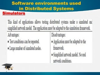
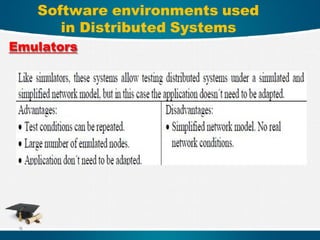
Software environments for distributed systems
Real environments for distributed systems
Communication operations used in distributed
systems
Parallel computing systems
Switching mechanisms/techniques used in
distributed systems
Deadlock detection in distributed systems
Fault tolerant multicast in distributed systems
2
3.
Distributed Systems
A DISTRIBUTEDSYSTEM:
is a collection of independent entities that
cooperate to solve a problem that cannot
be individually solved.
isone in which components located at
networked computers, communicate and
coordinate their actions only by passing
messages.
3
• Concurrency:
In anetwork of computers, concurrent program
execution is the norm. A key complexity with
concurrency is handling shared access to
resources
• No global clock:
When programs need to cooperate, they
coordinate their actions by exchanging
messages.
• Independent failures:
All computer systems can fail, and it is the
responsibility of system designers to plan for the
consequences of possible failures.
Main characteristics of
Distributed Computing Systems
6.
• Efficiency
measures theutilization rate of resources
in an execution model by exploiting
massive parallelism.
• Dependability
measures the reliability and self-
management from the chip to the system
and application levels.
Design Objectives of Distributed
Computing Systems
7.
Design Objectives ofDistributed
Computing Systems(cont.)
Adaptation in the programming
model: measures the ability to support
billions of job requests over massive
data sets and virtualized cloud
resources under various workload and
service models.
Flexibility in application
deployment :measures the ability of
distributed systems to run well in all
applications.
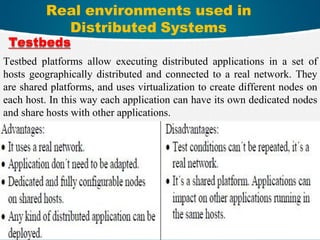
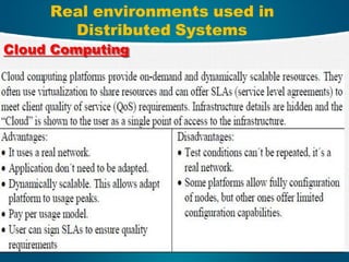
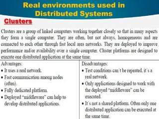
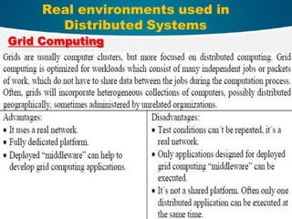
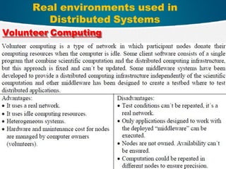
Real environments usedin
Distributed Systems
10
Testbeds
Testbed platforms allow executing distributed applications in a set of
hosts geographically distributed and connected to a real network. They
are shared platforms, and uses virtualization to create different nodes on
each host. In this way each application can have its own dedicated nodes
and share hosts with other applications.
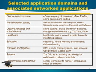
Selected application domainsand
associated networked applications
15
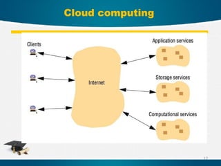
Finance and commerce eCommerce e.g. Amazon and eBay, PayPal,
online banking and trading
The information society Web information and search engines, ebooks,
Wikipedia; social networking: Facebook and MySpace.
Creative industries and
entertainment
online gaming, music and film in the home,
user-generated content, e.g. YouTube, Flickr
Healthcare health informatics, on online patient records,
monitoring patients
Education e-learning, virtual learning environments;
distance learning
Transport and logistics GPS in route finding systems, map services:
Google Maps, Google Earth
Science The Grid as an enabling technology for
collaboration between scientists
Environmental management sensor technology to monitor earthquakes,
floods or tsunamis
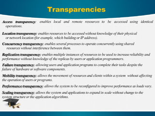
Transparencies
enables local andremote resources to be accessed using identical
Access transparency:
operations.
Location transparency: enables resources to be accessed without knowledge of their physical
or network location (for example, which building or IPaddress).
Concurrency transparency: enables several processes to operate concurrently using shared
resources without interference between them.
Replication transparency: enables multiple instances of resources to be used to increase reliability and
performance without knowledge of the replicas by users or application programmers.
Failure transparency: allowing users and application programs to complete their tasks despite the
failure of hardware or software components.
Mobility transparency: allows the movement of resources and clients within a system without affecting
the operation of users or programs.
Performance transparency: allows the system to be reconfigured to improve performance as loads vary.
Scaling transparency: allows the system and applications to expand in scale without change to the
system structure or the application algorithms.
19.
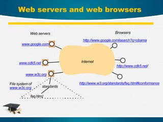
Web servers andweb browsers
Internet
Web servers
www.google.com
www.cdk5.net
www.w3c.org
standards
faq.html
http://www.w3.org/standards/faq.html#conformance
Browsers
http://www.google.comlsearch?q=obama
http://www.cdk5.net/
File system of
www.w3c.org
What is WormholeSwitching
Wormhole switching is a packet
switching technique used in
parallel computing networks and
Network-on-Chip (NoC)
architectures. This technique helps
reduce latency and improve
resource utilization when
transmitting data across a network
25.
Basic Concept
Instead ofsending an entire packet to one node before
forwarding, the packet is divided into very small parts
called Flits (Flow Control Digits), which move
sequentially through the network. Once the first Flit is
sent, the rest follow without waiting for the full packet
to reach the next node
26.
Main Components ofa Packet in
Wormhole Switching
1. Header Flit: The Header Flit contains routing
information, such as the destination and path of
the packet.
2. Body Flits: Body Flits carry thactual data
being transmitted.
3. Tail Flit: The Tail Flit marks the end of
the packet, allowing nodes to release
resources after transmission is
complete.
27.
How Does WormholeSwitching
Work?
1. When a data packet needs to travel through
the network, it is divided into Flits.
2. The Header Flit is sent first, determining the
path of the packet
3. Once the path is determined, the Body Flits and Tail
Flit follow in sequence along the same route.
4. if a Flit encounters congestion or stops for
any reason, all following Flits stop as well,
leading to a condition called Blocking.
28.
Advantages of WormholeSwitching
1)Lower Latency: Data flows continuously
without requiring full packet storage at
each node, reducing latency
2)Lower Memory Usage: Nodes do not
need to store entire packets, requiring only
small buffers for a few Flits
29.
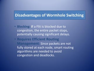
Disadvantages of WormholeSwitching
• Blocking: if a Flit is blocked due to
congestion, the entire packet stops,
potentially causing significant delays.
• Requires Efficient Routing
Management: Since packets are not
fully stored at each node, smart routing
algorithms are needed to avoid
congestion and deadlocks.
30.
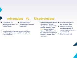
▸ More reliableas a
destination can detect the
missing packet.
Advantages Vs Disadvantages
30
▸ Cost-effective and
comparatively cheaper to
implement.
▸ More fault tolerant because packets may follow
a different path in case any link is down, Unlike
Circuit Switching
▸ Overall packet delay can vary
substituting ,The delay
changes from one packet to
another, and this is called
jitter, and this happens
because of the difference in
the size of the packet and the
methods it takes to reach
destination
▸ Packet Switching doesn’t
give packets in order.
▸ Since the packets are
unordered, we need to
provide sequence numbers
for each packet.
▸ Delay form each node
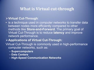
What is Virtualcut-through
Virtual Cut-Through:
• is a technique used in computer networks to transfer data
between nodes more efficiently compared to other
methods like Store-and-Forward. The primary goal of
Virtual Cut-Through is to reduce latency and improve
network performance.
Applications of Virtual Cut-Through:
Virtual Cut-Through is commonly used in high-performance
computer networks, such as:
– Supercomputers
– Data Centers
– High-Speed Communication Networks
33.
How Virtual Cut-ThroughWorks
1. Starting the Transmission:
– When a node wants to send a data packet to another node, it breaks
the packet into smaller units called flits (Flow Control Digits).
– These flits are sent sequentially through the network
2. Routing:
– Once the first flit (called the Header Flit) reaches an intermediate
node, the node examines the destination address and determines the
next path the flits should take.
– If the path is available, the intermediate node starts forwarding the flits
immediately as they arrive, without waiting for the entire packet to be
received.
34.
How Virtual Cut-ThroughWorks
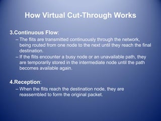
3.Continuous Flow:
– The flits are transmitted continuously through the network,
being routed from one node to the next until they reach the final
destination.
– If the flits encounter a busy node or an unavailable path, they
are temporarily stored in the intermediate node until the path
becomes available again.
4.Reception:
– When the flits reach the destination node, they are
reassembled to form the original packet.
35.
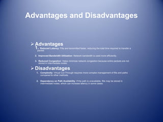
Advantages and Disadvantages
Advantages
1.Reduced Latency: Flits are transmitted faster, reducing the total time required to transfer a
packet.
2. Improved Bandwidth Utilization: Network bandwidth is used more efficiently.
3. Reduced Congestion: Helps minimize network congestion because entire packets are not
stored in intermediate nodes.
Disadvantages
1. Complexity: Virtual Cut-Through requires more complex management of flits and paths
compared to other methods.
2. Dependency on Path Availability: If the path is unavailable, flits may be stored in
intermediate nodes, which can increase latency in some cases.
36.
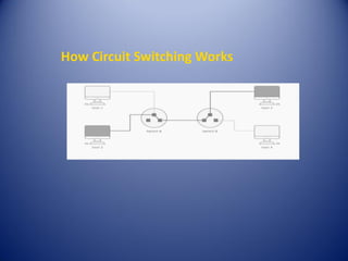
What is CircuitSwitching?
Circuit Switching is a network configuration where a
dedicated physical path is established between two
endpoints for the duration of the connection.
Example: Traditional landline phone calls establish a
dedicated line for the entire call duration.
- Bandwidth and data transmission rates are fixed.
- This is a Connection-Oriented method, requiring a
physical connection setup before data transfer.
37.
Usages of CircuitSwitching
- Landline phone calls (especially for long-
distance communications).
- Dial-up internet connections (used in the
early days of internet access).
- Optical circuit switching (used in large
data centers to handle growing data
requirements).
38.
Phases of CircuitSwitching
1. Connection Establishment: A dedicated
circuit is established between the two
communicating parties.
2. Data Transfer: Data flows between the
source and destination over the
established circuit.
3. Connection Teardown: Once the
communication is finished, the circuit is
released and available for new
connections.
Advantages of CircuitSwitching
- Dedicated Channel: Reserved path for
communication between two endpoints.
- Reliability: Stable and consistent
connection with minimal data loss.
- Security: More secure due to dedicated
circuit usage.
- Quality: High-quality, uninterrupted
communication once the connection is
established.
41.
Disadvantages of CircuitSwitching
- Limited Use: Primarily for voice
communication.
- Inefficient: Resources are reserved even
if no data is being transmitted.
- Inflexible: Less adaptable to varying
traffic loads.
- Higher Cost: More expensive due to the
dedicated infrastructure.
- Latency: Time is required to establish the
connection before data can be transferred.
42.
Packet Switching vs.Circuit
Switching
- Circuit Switching: Connection-Oriented.
Fixed dedicated path. Used for continuous
data transfer.
- Packet Switching: Connectionless. Data is
divided into packets and sent
independently. More flexible and efficient
for modern data communication.
43.
43
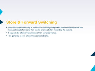
▸ Store-and-forward switchingis a method of switching data packets by the switching device that
receives the data frame and then checks for errors before forwarding the packets.
▸ It supports the efficient transmission of non-corrupted frames.
▸ It is generally used in telecommunication networks.
Store & Forward Switching
44.
44
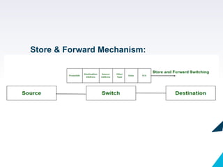
▸ In store-and-forwardswitching, the switching device waits to receive the entire frame and then
stores the frame in the buffer memory. Then the frame is checked for errors by using CRC(Cyclic
Redundancy Check) if the error is found then the packet is discarded else it is forwarded to the
next device.
Store & Forward mechanism:
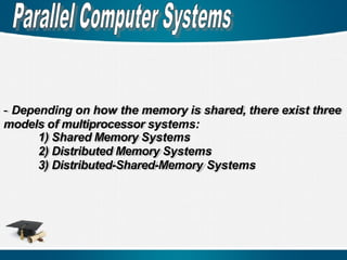
- Depending onhow the memory is shared, there exist three
models of multiprocessor systems:
1) Shared Memory Systems
2) Distributed Memory Systems
3) Distributed-Shared-Memory Systems
47.
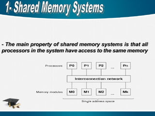
- The mainproperty of shared memory systems is that all
processors in the system have access to the same memory
48.
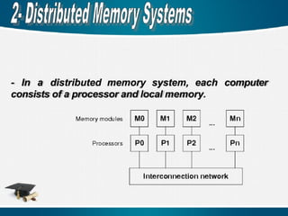
- In adistributed memory system, each computer
consists of a processor and local memory.
49.
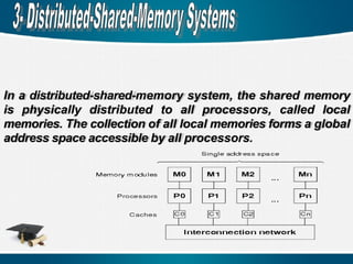
In a distributed-shared-memorysystem, the shared memory
is physically distributed to all processors, called local
memories. The collection of all local memories forms a global
address space accessible by all processors.
50.
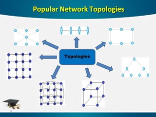
The interconnection networksare used for internal
connections among processors, memory modules, and
I/o devices in a shared-memory system or among nodes
in a distributed-memory system.
The topology of an interconnection network defines how
the nodes are interconnected by channels. Basically,
there are two kinds of interconnection networks, indirect
(dynamic) and direct (static)
51.
Communication mechanisms canbe classified into
several classes according to the number of source and
destination nodes and the way how the transferred
information is handled.
1 One-to-One Communication
2 One-to-Many Communication
3 Many-to-One Communication
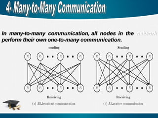
4 Many-to-Many Communication
52.
In one-to- onecommunication, each node can send at
most one message and receive at most one message.
There are n! different communication patterns. If there
exist more than one source node and destination node,
thus called multiple one-to-one communication.
53.
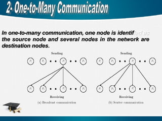
In one-to-many communication,one node is identified as
the source node and several nodes in the network are
destination nodes.
Network Fault Issues
Indistributed-memory systems, some components such as
processors, routers, and communication channels may fail
(fault).
Fault tolerance refers to the ability of the system to operate
correctly in the presence of faults.
The two most important fault regions are regular (convex,
concave) and irregular faults.
60
61.
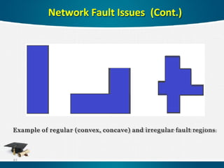
Network Fault Issues(Cont.)
Example of regular (convex, concave) and irregular fault regions
61
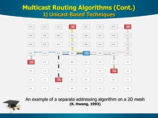
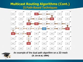
62.
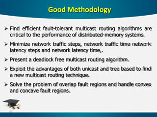
Find efficientfault-tolerant multicast routing algorithms are
critical to the performance of distributed-memory systems.
Minimize network traffic steps, network traffic time network
latency steps and network latency time,.
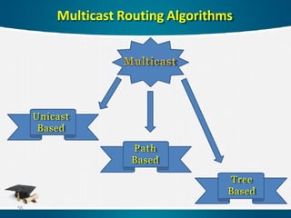
Present a deadlock free multicast routing algorithm.
Exploit the advantages of both unicast and tree based to find
a new multicast routing technique.
Solve the problem of overlap fault regions and handle convex
and concave fault regions.
Good Methodology
62
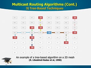
63.
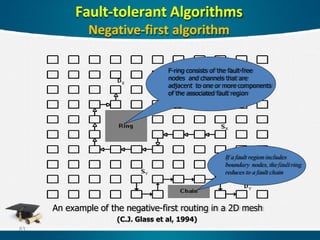
An example ofthe negative-first routing in a 2D mesh
(C.J. Glass et al, 1994)
Fault-tolerant Algorithms
Negative-first algorithm
F-ring consists of the fault-free
nodes and channels that are
adjacent to one or more components
of the associated fault region
If a fault region includes
boundary nodes, the fault ring
reduces to a fault chain
63
64.
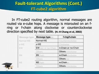
In FT-cube2 routingalgorithm, normal messages are
routed via e-cube hops. A message is misrouted on an f-
ring or f-chain along clockwise or counterclockwise
direction specified by next table. (H.-H Chang et al, 2002)
Message type f-ring/f-chain
Normal-WE
s-WE
EW n-Chain or nw-Chain
Others
SN w-Chain
Others
NS w-Chain
Others
Fault-tolerant Algorithms (Cont.)
FT-cube2 algorithm
64
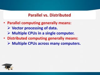
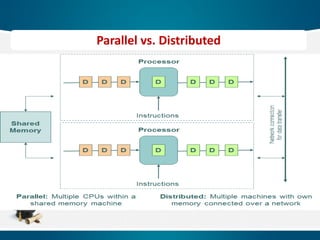
• Parallel computinggenerally means:
Vector processing of data.
Multiple CPUs in a single computer.
• Distributed computing generally means:
Multiple CPUs across many computers.
Parallel vs. Distributed
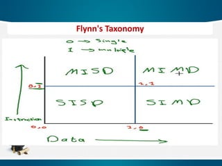
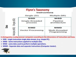
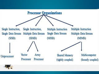
It distinguishes multiprocessorcomputers according to the dimensions of Instruction and Data:
SISD - single instruction single data stream, (e.g. simple PC).
SIMD - Same instructions applied to multiple data.
MISD - same data used to perform multiple operations.
MIMD - Separate data and separate instructions (Computer cluster).
Flynn's Taxonomy
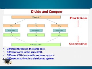
• Different threadsin the same core.
• Different cores in the same CPU.
• Different CPUs in a multi-processor system.
• Different machines in a distributed system.
Divide and Conquer
72.
72
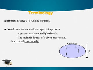
A process: instanceof a running program.
A thread: uses the same address space of a process.
A process can have multiple threads.
The multiple threads of a given process may
be executed concurrently.
Terminology
73.
73
Terminology
Task granularity: thesize of tasks
Scheduling: is the assignment of tasks to processes or threads and
fixes the order in which the tasks are executed.
Mapping: is the assignment of processes or threads onto the physical
units, processors or cores.
74.
74
Terminology
Parallel execution time:which consists of the time for the
computation on processors or cores and the time for the data
exchange or synchronization.
Idle times: in which a processor cannot do anything useful,
but wait for an event to happen.
75.
75
Terminology
Parallel processing/computing canbe subdivided into two groups, either
task based or data based.
Task based: every processor in the system will execute different job or
tasks in a parallel way.
Data based: the same task is executed, but over different data sets.
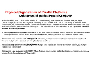
Physical Organization ofParallel Platforms
Architecture of an Ideal Parallel Computer
A natural extension of the serial model of computation (the Random Access Machine, or RAM)
consists of p processors and a global memory of unbounded size that is uniformly accessible to all
processors. All processors access the same address space. Processors share a common clock but may
execute different instructions in each cycle. This ideal model is also referred to as a parallel random
access machine (PRAM).
1. Exclusive-read, exclusive-write (EREW) PRAM. In this class, access to a memory location is exclusive. No concurrent read or
write operations are allowed. This is the weakest PRAM model, affording minimum concurrency in memory access.
2. Concurrent-read, exclusive-write (CREW) PRAM. In this class, multiple read accesses to a memory location are allowed.
However, multiple write accesses to a memory location are serialized.
3. Exclusive-read, concurrent-write (ERCW) PRAM. Multiple write accesses are allowed to a memory location, but multiple
read accesses are serialized.
4. Concurrent-read, concurrent-write (CRCW) PRAM. This class allows multiple read and write accesses to a common memory
location. This is the most powerful PRAM model.
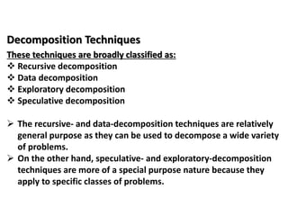
Decomposition Techniques
These techniquesare broadly classified as:
Recursive decomposition
Data decomposition
Exploratory decomposition
Speculative decomposition
The recursive- and data-decomposition techniques are relatively
general purpose as they can be used to decompose a wide variety
of problems.
On the other hand, speculative- and exploratory-decomposition
techniques are more of a special purpose nature because they
apply to specific classes of problems.
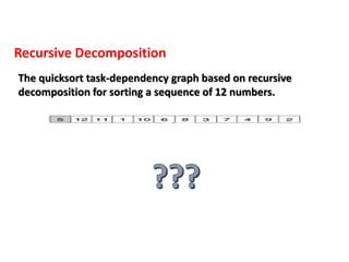
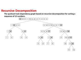
The quicksort task-dependencygraph based on recursive decomposition for sorting a
sequence of 12 numbers.
Recursive Decomposition
82.
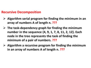
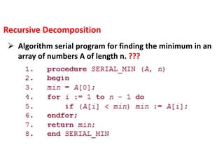
Algorithm serialprogram for finding the minimum in an
array of numbers A of length n. ???
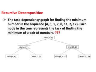
The task-dependency graph for finding the minimum
number in the sequence {4, 9, 1, 7, 8, 11, 2, 12}. Each
node in the tree represents the task of finding the
minimum of a pair of numbers. ???
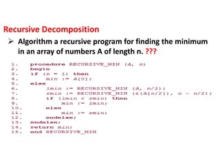
Algorithm a recursive program for finding the minimum
in an array of numbers A of length n. ???
Recursive Decomposition
83.
Algorithm serialprogram for finding the minimum in an
array of numbers A of length n. ???
Recursive Decomposition
84.
The task-dependencygraph for finding the minimum
number in the sequence {4, 9, 1, 7, 8, 11, 2, 12}. Each
node in the tree represents the task of finding the
minimum of a pair of numbers. ???
Recursive Decomposition
85.
Algorithm arecursive program for finding the minimum
in an array of numbers A of length n. ???
Recursive Decomposition
86.
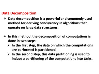
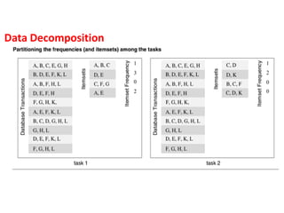
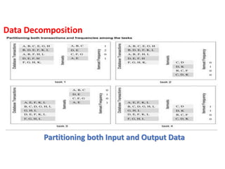
Data decompositionis a powerful and commonly used
method for deriving concurrency in algorithms that
operate on large data structures.
In this method, the decomposition of computations is
done in two steps:
In the first step, the data on which the computations
are performed is partitioned
In the second step, this data partitioning is used to
induce a partitioning of the computations into tasks.
Data Decomposition
87.
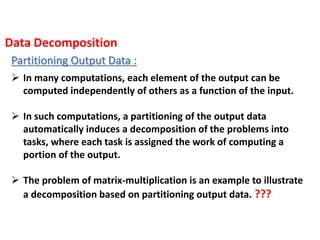
Partitioning Output Data:
In many computations, each element of the output can be
computed independently of others as a function of the input.
In such computations, a partitioning of the output data
automatically induces a decomposition of the problems into
tasks, where each task is assigned the work of computing a
portion of the output.
The problem of matrix-multiplication is an example to illustrate
a decomposition based on partitioning output data. ???
Data Decomposition
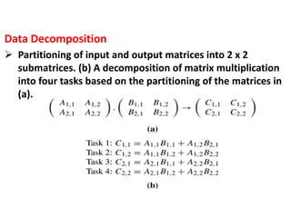
88.
Partitioning ofinput and output matrices into 2 x 2
submatrices. (b) A decomposition of matrix multiplication
into four tasks based on the partitioning of the matrices in
(a).
Data Decomposition
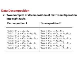
89.
Two examplesof decomposition of matrix multiplication
into eight tasks.
Data Decomposition
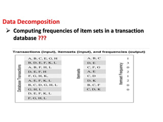
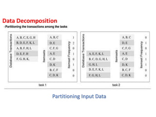
Partitioning input Data:
Partitioning of output data can be performed only if each
output can be naturally computed as a function of the input.
In many algorithms, it is not possible or desirable to partition
the output data.
For example, while finding the minimum, maximum, or the sum
of a set of numbers, the output is a single unknown value.
Data Decomposition
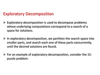
Exploratory Decomposition
Exploratorydecomposition is used to decompose problems
whose underlying computations correspond to a search of a
space for solutions.
In exploratory decomposition, we partition the search space into
smaller parts, and search each one of these parts concurrently,
until the desired solutions are found.
For an example of exploratory decomposition, consider the 15-
puzzle problem.
96.
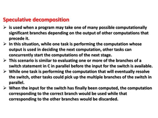
Speculative decomposition
isused when a program may take one of many possible computationally
significant branches depending on the output of other computations that
precede it.
In this situation, while one task is performing the computation whose
output is used in deciding the next computation, other tasks can
concurrently start the computations of the next stage.
This scenario is similar to evaluating one or more of the branches of a
switch statement in C in parallel before the input for the switch is available.
While one task is performing the computation that will eventually resolve
the switch, other tasks could pick up the multiple branches of the switch in
parallel.
When the input for the switch has finally been computed, the computation
corresponding to the correct branch would be used while that
corresponding to the other branches would be discarded.
97.
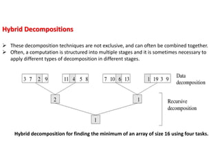
Hybrid Decompositions
Thesedecomposition techniques are not exclusive, and can often be combined together.
Often, a computation is structured into multiple stages and it is sometimes necessary to
apply different types of decomposition in different stages.
Hybrid decomposition for finding the minimum of an array of size 16 using four tasks.
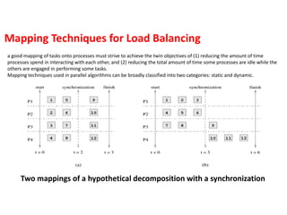
Two mappings ofa hypothetical decomposition with a synchronization
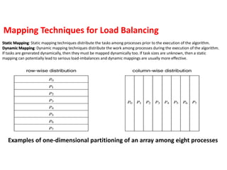
Mapping Techniques for Load Balancing
a good mapping of tasks onto processes must strive to achieve the twin objectives of (1) reducing the amount of time
processes spend in interacting with each other, and (2) reducing the total amount of time some processes are idle while the
others are engaged in performing some tasks.
Mapping techniques used in parallel algorithms can be broadly classified into two categories: static and dynamic.
100.
Examples of one-dimensionalpartitioning of an array among eight processes
Mapping Techniques for Load Balancing
Static Mapping: Static mapping techniques distribute the tasks among processes prior to the execution of the algorithm.
Dynamic Mapping: Dynamic mapping techniques distribute the work among processes during the execution of the algorithm.
If tasks are generated dynamically, then they must be mapped dynamically too. If task sizes are unknown, then a static
mapping can potentially lead to serious load-imbalances and dynamic mappings are usually more effective.
101.
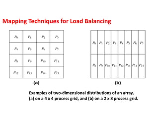
Examples of two-dimensionaldistributions of an array,
(a) on a 4 x 4 process grid, and (b) on a 2 x 8 process grid.
Mapping Techniques for Load Balancing
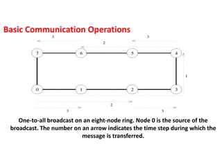
One-to-all broadcast onan eight-node ring. Node 0 is the source of the
broadcast. The number on an arrow indicates the time step during which the
message is transferred.
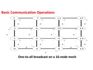
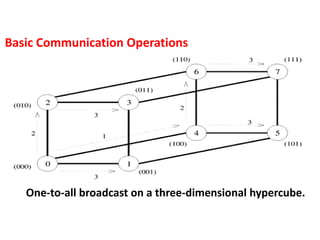
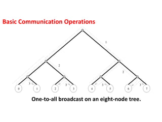
Basic Communication Operations
104.
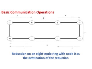
Reduction on aneight-node ring with node 0 as
the destination of the reduction
Basic Communication Operations