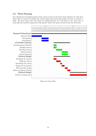
This document provides details on a research project investigating heterogeneous wireless robotic networks. It outlines requirements for the microcontroller systems to control master and slave robots. Cheaper slave robots will use Arduino Nanos, while the more advanced master robot will use a Raspberry Pi to process sensor data and coordinate slave movements. Communication between robots will use nRF24L01+ modules. Robot location will be determined using ultrasonic ranging and direction from RGB LEDs and image processing. The implementation plan and research activities are also summarized.
![3 Mirco-Controller Systems
The micro-controller systems section has been broken down into subsections of Micro-controller selec-
tion, Wireless communications, Robot locationing, movement planning and sensor control systems.
3.1 Micro-Controller Selection
This project will require microcontrollers to control both the Master and Slave robots, given that
the intent of the project is to show that the slave robots can be as cheap as possible we will need to
select two different microcontrollers, one simple controller used only for running the slave robot and
one complex controller for running the master robot and calculating the instructions for each of the
slaves.
For the microcontroller of the slave robot, our requirements are that it needs to be able to communicate
with the wireless module we chose, run the motors, and read the sensors. These requirements are
met by almost all micorcontroller boards on the market today.
For the microcontroller of the master robot our requirements are much more advanced than the that
of the slave robots. The master robot must meet all the requirements of the slave robots, as well
as process the image feedback sensor, and the swarm route planning of all the slave robots. These
requirements are very high for an embedded system, this adds in the possibility of being able to offload
this processing to an external computer for analysis and computation, therefore the requirements of
the master controller are that it can network wirelessly with a computation computer, interface with
a camera, and run the motors and sensors of the robot.
Given the requirements set out each of the controllers, we have chosen to use the Arduino Nano for
the slave and the Raspberry-PI controller for the Master.
3.2 Communications
3.2.1 Network Topology
The wireless robotic network we have proposed requires each node to be able to communicate with the
master robot, and for the propagation delay to be as small as possible. The data throughput of the
pipelines between the master and slaves is very minimal.We will also need the ability to communicate
with an external computer to compute harder calculations.
3.2.2 Communications Modules
Allowing for these considerations we have chosen to use the nordic NRF-24l01+, it allows for multiple
channels of communication and is compatible with the arduino and raspberry-pi selected for control-
ling the robots.
We would also choose to add on a wifi attachment to the raspberry pi for the connection to the
external computer.
3.3 Robot locationing
3.3.1 Range
For range detection of the robots we will use the Cricket feedback system,the Cricket feedback system
is based on using two signals with different travel speeds, and comparing the differences [1]. For our
project we will evaluate the effectiveness of using an ultrasound speaker/receiver as the slow signal,
and using either and rf signal or IR light signal as the fast travelling signal.The advantages of using
an RF based system is that the receiver and transmitter don’t need to be within line-of-sight of each
other to work, however the disadvantages are that receiving and RF signal may take some processing
time and produce inaccurate results. The advantages of an IR light bases system are that there is no
processing time to detect a signal, however the disadvantages of the IR based system is that emitters
and detectors need to be in line of sight of each other.
2](https://image.slidesharecdn.com/5fd04b91-e9e7-4108-9516-c7ee878c143a-160319030021/85/Final-Report-9505482-5845742-5-320.jpg)
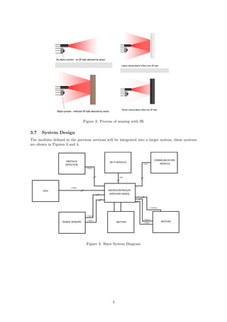
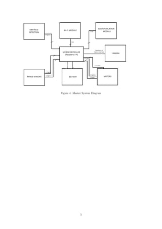
![3.3.2 Direction
For the master robot to be able to detect the direction of the slave robots we will place a camera on
the master robot and RGB LED’s on the top of each of the slave robots. The image captured by the
camera will be filtered of all colours but the basic colours the robots are projecting, and then will
find the angle of each robot by using a lookup table of pixels on the image to directions of the robot.
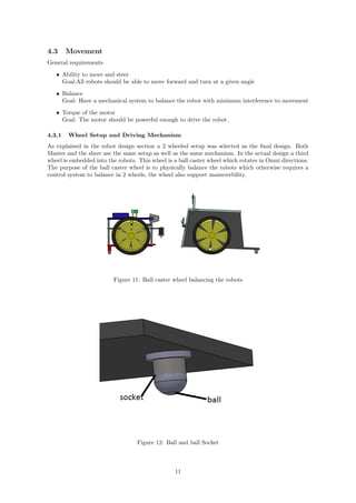
3.4 Movement Planning
For the movement planning of the robots we will be following the system of outlined in [2]. This
will require the master robot to have an updated location of each of the slave robots, and updated
information about what the slave can sense in the adjacent areas. We will have to optimise the values
each area receive so that none of the movement requests sent from the master robot cause the slaves
to go out of line of sight of each other and the master.
Figure 1: Example of the view the system can have of the robots in action
3.5 Sensors and Control Systems
For our robot accurate position data is much more important than velocity information so we have
decided to use only positional feedback of the wheels. Positional feedback can be created through
potentiometer feedback, or using rotary encoder.
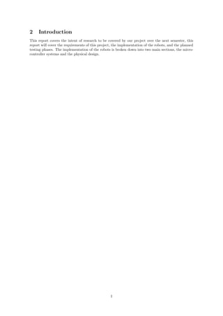
3.6 Obstacle Detection
IR sensor is used for obstacle detection in slave robots. IR sensor is very important for the project
since IR sensor will be the one that detect obstacle and therefore collecting the most important data
for the mapping process.
A basic IR sensor uses an emitter and receiver. When the emitter emits the IR light on to a surface
the reflected light will be absorbed by the detector. In this project, IR sensor will be active through-
out the operation, when the slave robot detects an obstacle it will send the data to the master to
create a map. The effectiveness will however vary with the colour on the surface of the obstacle;
darker obstacle will absorb most of the light emitted by the emitter leaving only few reflections to be
detected by the detector.
3](https://image.slidesharecdn.com/5fd04b91-e9e7-4108-9516-c7ee878c143a-160319030021/85/Final-Report-9505482-5845742-6-320.jpg)
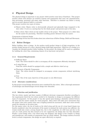
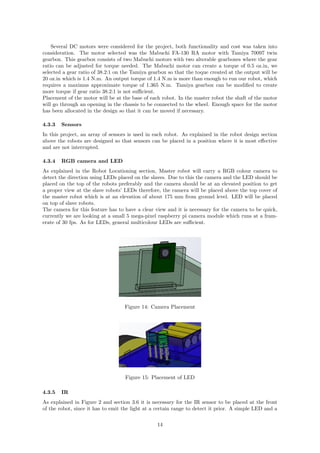
![In this project the driving mechanism uses the voltage input given to the DC motors through the
controller. Therefore to move straight one must make sure that both wheels turn in-sync to each
other. To reduce such error, a rotary encoder is used which will count the rotations of the motor and
acts according to the motor feedback.
To turn, the motor on the opposite direction must spin faster than the one on the turning side, if
not the motor on the turning side has to be inactive/idle. This diagram of our slave robot shows two
positions of the same robot, while moving forward both motors are active, when turning the motor
has stopped temporary.
Figure 13: Driving mechanism in the robots
4.3.2 Motor
Alternate considerations The motor is an uttermost valuable part of this project; it is the limbs of the
robot. It has been somewhat difficult to select the capacity of motor without a proper understanding
of the power consumption by other components. It is also difficult to place the motor without assess-
ing the actual build. When placing the motor factors such as centre of gravity of the whole system
has to be considered to adjust the placement of the motor so as to get the maximum torque output.
Requirements
• Sufficient Torque
Goal: The motors should create enough torque to move the robot
• Small, light yet powerful
Goal: Motors must be light enough to be carried, small enough to fit in to the design.
• Cost
Goal: Cost effectiveness is one of the main objectives in this project
First we calculated the Weight of the two robots.
We assumed thickness of acrylic is 3 mm, therefore for 1 square feet (0.092 square meters) the mass
of acrylic was close to 350 g
Another assumption that we assumed Acrylonitrile butadiene styrene (ABS) was used as the 3D
printing material, which is a very common material used in rapid prototyping. The minimum density
of ABS pellet was found out [3] to be 720 kg/m3. Using that we calculated [4] the mass of master
robot’s chassis, there width was selected as 30mm since the chassis is not a solid cuboid. We also
calculated the mass of slave robot’s base. We also calculated the mass of the wheel.
We assumed 6 AA batteries are used for a voltage of 7.2 V at 2A. Mass of a AA battery is roughly
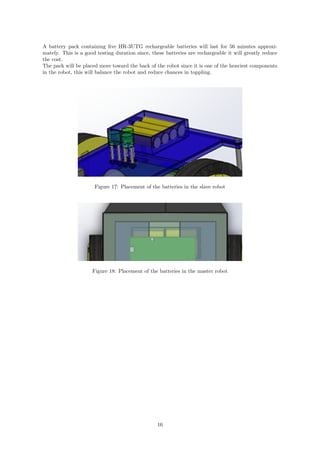
0.025 kg [5]. This table consists of total mass approximation of each robot.
12](https://image.slidesharecdn.com/5fd04b91-e9e7-4108-9516-c7ee878c143a-160319030021/85/Final-Report-9505482-5845742-15-320.jpg)
![Mass for Master Robot Mass for a slave Robot
3D printed components Chassis - 0.43kg Base- 0.055kg
Wheels - 0.32kg Wheels 0.32kg
Acrylic components 0.5kg 0.3kg
Battery 0.15kg 0.15kg
2 Motor 0.05kg 0.05kg
Microcontroller 0.045kg 0.025kg
Electronic components 0.1kg 0.1kg
Other 0.05kg 0.05kg
Total 1.195kg 1.05kg
We can calculate
the weight of robots by using W = mg; Assuming g = 9.81 m/s/s Therefore, the weight of Mas-
ter Robot is approximately 11.7 N and the Weight of a Slave robot is 10.3 N approximately.
Using mass we can calculate the rolling friction Fr for a single wheel.
Since the project focuses on indoor robots, we can assume there is no air friction therefore rolling
friction is the only force that opposes motion of our robot. So, Torque equation was used to calculate
the torque for a single motor for a single rotation of a wheel.
Several assumptions were made in this calculation;
1. Weight carried by the caster wheel is neglected.
2. Each wheel share equally share the weight of the robot thus, W/2
3. Rolling coefficient b for a car tire on a concrete surface is 0.01-0.015 [5], since we are testing
robots on a smooth tile a lower value 0.01 was used.
4. No air friction
5. Robot travels roughly d= 0.14 m linearly for a single rotation of the wheel; circumference of
the wheel is 0.14 m
Rolling friction equation
Fr =
W × b
r
(1)
W is weight, b is rolling friction coefficient and r is the radius Torque equation
τ = F × d (2)
τ is torque, F is Force and d is Linear distance travelled For the master Robot
Fr =
11.7/2 × 0.01
0.06
= 0.975N (3)
τ = 0.975 × 0.14 = 0.1365N ∗ M (4)
For the slave Robot
Fr =
10.5/2 × 0.015
0.06
= 0.86N (5)
τ = 0.86 × 0.14 = 0.1204N ∗ M (6)
Both robots will use the same type of motor since the difference in load (mass) is only about 0.15 kg.
Since lots of assumptions and approximations are used, It is better to select a motor where toque is
in excess of highest calculated value- 0.1365 Nm.
Initially the motors selected for this project were unipolar stepper motors, stepper motors are
brushless DC motors which consists of electromagnetic switches that can lock the shaft in a position.
When the motor has rotated in a desired angle two electro magnets around the shaft that are opposite
to each other will create a field that will lock the shaft in place. Upon research it was realized that
using a generic DC motor with a gearbox is simple and also cost effective
13](https://image.slidesharecdn.com/5fd04b91-e9e7-4108-9516-c7ee878c143a-160319030021/85/Final-Report-9505482-5845742-16-320.jpg)
![photodiode can be uses as the emitter and receiver. The two components of the sensor will be placed
at the top level of the slave robot next to each other as shown below.
Figure 16:
4.3.6 Battery
There are many types of batteries that can be used to power robots in this project. The intention
was to search for a battery that fulfils these requirements.
Requirements
• Sufficient power output
Goal: Find a battery with enough voltage and current output
• Duration
Goal: Battery should last for a considerable testing period
• Mass
Goal: The Battery shouldn’t be extremely heavy
• Cost
Goal: Cost effectiveness is one of the main objectives in this project
Before selecting a sufficient battery, we looked into power required by each major component i.e.
Motor and the microcontroller. Small components such as LEDs and IR sensors which require a low
voltage and low current were vaguely considered for this assumption as the power is controlled by
the microcontroller. The value are for the components used in master robot, the slave robot uses less
power the choice of battery will fit both robots.
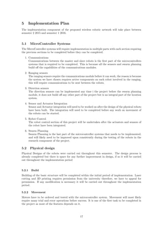
Maximum voltage Current at Maximum efficiency Power
Motors 3 V 1.32 A 4 W (for both)
Microcontroller 5V 0.8 A 4 W
Total required input 5 V 2.12 A 8W
The
batteries that is seemed efficient were the rechargeable AA batteries but, a set of AA battery will be
connected in series to supply enough voltage since a single AA battery can only supply a voltage in
the range of 1.2 – 1.5 V. A specific rechargeable battery HR- 3UTG can supply 1.2 V at 2 Ah [8]
which means the battery can supply 2A for an hour before recharging. Since we require a maximum
voltage of 5V, at least 5 of these batteries will need to be connected in series. If we assume that we
use a battery pack that contain five HR- 3UTG rechargeable batteries, the battery pack will supply
a current of 2A with a voltage of 6V.
Duration(h) =
Capacity(Ah)
RequiredCurrent(A)
(7)
Capacity of the battery is 2 Ah and the required total current is 2.12 A.
Duration(h) =
2(Ah)
2.12(A)
= 0.943hours = 56mins (8)
15](https://image.slidesharecdn.com/5fd04b91-e9e7-4108-9516-c7ee878c143a-160319030021/85/Final-Report-9505482-5845742-18-320.jpg)
![References
[1] N. B. Priyantha, A. Chakraborty, and H. Balakrishnan, “The cricket location-support system,”
in Proceedings of the 6th annual international conference on Mobile computing and networking,
pp. 32–43, ACM, 2000.
[2] M. N. Rooker and A. Birk, “Multi-robot exploration under the constraints of wireless networking,”
Control Engineering Practice, vol. 15, no. 4, pp. 435–445, 2007.
[3] “Densities of some common materials.”
[4]
[5] “The dimensions, usage and capacity of the aa batteries.”
21](https://image.slidesharecdn.com/5fd04b91-e9e7-4108-9516-c7ee878c143a-160319030021/85/Final-Report-9505482-5845742-24-320.jpg)
![wronski_ugthesis[1]](https://cdn.slidesharecdn.com/ss_thumbnails/95db93fc-5f15-4802-985f-832034d277d7-150202014804-conversion-gate02-thumbnail.jpg?width=640&height=640&fit=bounds)


![[Year 2105-16]Pollution Monitoring using Cooperative Wireless Communication f...](https://cdn.slidesharecdn.com/ss_thumbnails/ppt-180701110957-thumbnail.jpg?width=640&height=640&fit=bounds)