Download as PDF, PPTX


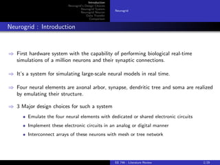
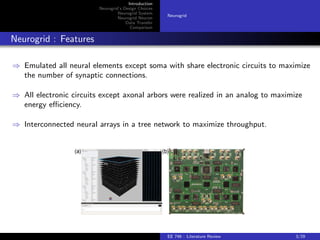


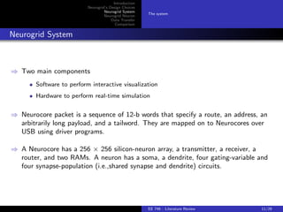
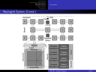


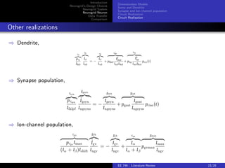
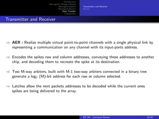
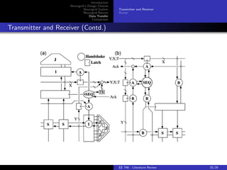
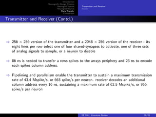

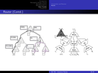


The document discusses the Neurogrid system, which was the first hardware system capable of simulating a million neurons in real time. It describes Neurogrid's key design choices of emulating neural elements with shared circuits, implementing circuits in analog form, and connecting arrays in a tree network. The Neurogrid system consists of Neurocore chips containing 256x256 silicon neuron arrays interconnected in a tree network. Spikes are routed between chips using an address event representation scheme and multicast routing allows modeling axonal branching.