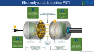
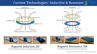
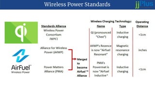
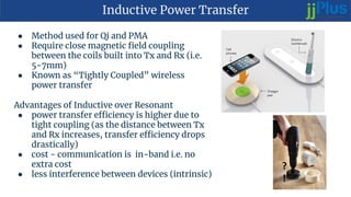
It's a project on wireless mobile charging based on inductive charging. Most cellular devices that supports wireless charging are based on this type of wireless charging. This is a simulation based project done using PSpice software.
PROJECT DESCRIPTION
DOWNLOAD
The main objective of this project is to develop a device for wireless power transfer. The concept of wireless power transfer was realized by Nikolas tesla. Wireless power transfer can make a remarkable change in the field of the electrical engineering which eliminates the use conventional copper cables and current carrying wires.
Based on this concept, the project is developed to transfer power within a small range. This project can be used for charging batteries those are physically not possible to be connected electrically such as pace makers (An electronic device that works in place of a defective heart valve) implanted in the body that runs on a battery.
The patient is required to be operated every year to replace the battery. This project is designed to charge a rechargeable battery wirelessly for the purpose. Since charging of the battery is not possible to be demonstrated, we are providing a DC fan that runs through wireless power.
This project is built upon using an electronic circuit which converts AC 230V 50Hz to AC 12V, High frequency. The output is fed to a tuned coil forming as primary of an air core transformer. The secondary coil develops a voltage of HF 12volt.
Thus the transfer of power is done by the primary(transmitter) to the secondary that is separated with a considerable distance(say 3cm). Therefore the transfer could be seen as the primary transmits and the secondary receives the power to run load.
Moreover this technique can be used in number of applications, like to charge a mobile phone, iPod, laptop battery, propeller clock wirelessly. And also this kind of charging provides a far lower risk of electrical shock as it would be galvanically isolated.
This paper presents a high voltage conversion at high sensitivity RF energy harvesting system for IoT applications. The harvesting system comprises bulk-to-source (BTMOS) differential-drive based rectifier to produce a high efficiency RF energy harvesting system. Low-pass upward impedance matching network is applied at the rectifier input to increase the sensitivity and output voltage. Dual-oxide-thickness transistors are used in the rectifier circuit to maintain the power efficiency at each stage of the rectifier. The system is designed using 0.18µm Silterra RF in deep n-well process technology and achieves 4.07V output at -16dBm sensitivity without the need of complex auxiliary control circuit and DC-DC charge-pump circuit. The system is targeted for urban environment.
Development of Wireless Power Transfer using Capacitive Method for Mouse Char...IJPEDS-IAES
Wireless power transfer (WPT) is a non-contact power transfer within a
distance. With the advantage of not-contact concept, WPT enhances the
flexibility movement of the devices. Basically, there are three types of the
WPT which are inductive power transfer (IPT), capacitive power transfer
(CPT) and acoustic power transfer (APT). Among these, capacitive power
transfer (CPT) has the advantages of confining electric field between coupled
plates, metal penetration ability and also the simplicity in circuit topologies.
Therefore, we focus on the capacitive method in this paper. To be specific,
this paper aims to develop a wireless mouse charging system using capacitive
based method. This method enables wireless power transmission from mouse
pad to a wireless mouse. Hence, no battery requires to power up the mouse.
In this paper, a high efficiency Class-E converter is described in details to
convert the DC source to AC and the compensation circuit of resonant tank is
also proposed at the transmitter side in order to improve the efficiency. In the
end, a prototype is developed to prove the developed method. The
performances analysis of the developed prototype is discussed and the future
recommendation of this technique is also presented.
High-efficiency 2.45 and 5.8 GHz dual-band rectifier design with modulated in...IJECEIAES
This paper presents a new rectifier design for radio frequency (RF) energy harvesting by adopting a particular circuit topology to achieve two objectives at the same time. First, work with modulated input signal sources instead of only continuous waveform (CW) signals. Second, operate with a wide input power range using the Wilkinson power divider (WPD) and two different rectifier diodes (HSMS2852 and SMS7630) instead of using active components. According to the comparison with dual-band rectifiers presented in the literature, the designed rectifier is a high-efficiency rectifier for wide RF power input ranges. A peak of 67.041% and 49.089% was reached for 2.45 and 5.8 GHz, respectively, for CW as the input signal. An efficiency of 72.325% and 45.935% is obtained with a 16 QAM modulated input signal for the operating frequencies, respectively, 69.979% and 54.579% for 8PSK. The results obtained demonstrate that energy recovery systems can use modulated signals. Therefore, the use of a modulated signal over a CW signal may have additional benefits.
A Novel Configuration of A Microstrip Power Amplifier based on GaAs-FET for I...IJECEIAES
Power Amplifiers (PA) are very indispensable components in the design of numerous types of communication transmitters employed in microwave technology. The methodology is exemplified through the design of a 2.45GHz microwave power Amplifier (PA) for the industrial, scientific and medical (ISM) applications using microstrip technology. The main design target is to get a maximum power gain while simultaneously achieving a maximum output power through presenting the optimum impedance which is characteristically carried out per adding a matching circuit between the source and the input of the power amplifier and between the load and the output of the power amplifier. A "T" matching technique is used at the input and the output sides of transistor for assure in band desired that this circuit without reflections and to obtain a maximum power gain. The proposed power amplifier for microwave ISM applications is designed, simulated and optimized by employing Advanced Design System (ADS) software by Agilent. The PA shows good performances in terms of return loss, output power, power gain and stability; the circuit has an input return loss of -38dB and an output return loss of -33.5dB. The 1-dB compression point is 8.69dBm and power gain of the PA is 19.4dBm. The Rollet's Stability measure B1 and the stability factor K of the amplifier is greater than 0 and 1 respectively, which shows that the circuit is unconditionally stable. The total chip size of the PA is 73.5× 36 mm 2 .
Abstract: We need energy for every day today work of our life. There are many conventional methods of energy generation but these are depleting very fastly hence non-conventional energy system is very essential at this time to our nation. So an alternate method of non conventional energy generation is proposed in this project. In this project we are generating electrical power as non-conventional method by simply walking or running on foot step.Here Dynamometer is used for converting mechanical energy into electrical energy. The voltage generated by this sensor is stored in battery which will be later on transmitted wirelessly to charge the mobiles.
Development of Class D Inverter for Acoustics Energy Transfer Implantable Dev...IJPEDS-IAES
The working principle of half-bridge Class D Parallel-Resonant Inverter
(PRI) as power amplifier is presented in this paper. Simulation of the model
is carried out using Proteus. In order to verify the simulation results, an
experimental verification is done. This inverter used to excite PZT
transducers at suggested resonant frequency of 416 kHz with power level
transferred through Acoustics Energy Transfer (AET) concept at about 80
mW. As experimental outcome result, the system managed to transfer energyof 66 mW to the receiver side.
Integrated cmos rectifier for rf-powered wireless sensor network nodesjournalBEEI
This article presents a review of the CMOS rectifier for radio frequency energy harvesting application. The on-chip rectifier converts the ambient low-power radio frequency signal coming to antenna to useable DC voltage that recharges energy to wireless sensor network (WSN) nodes and radiofrequency identification (RFID) tags, therefore the rectifier is the most important part of the radio frequency energy harvesting system. The impedance matching network maximizes power transfer from antenna to rectifier. The design and comparison between the simulation results of one- and multi-stage differential drive cross connected rectifier (DDCCR) at the operating frequencies of 2.44GHz, and 28GHz show the output voltage of the multi-stage rectifier doubles at each added stage and power conversion efficiency (PCE) of rectifier at 2.44GHz was higher than 28GHz. The (DDCCR) rectifier is the most efficient rectifier topology to date and is used widely for passive WSN nodes and RFID tags.
Design of Negative Resistance Oscillator with Rocord Low Phase NoiseTELKOMNIKA JOURNAL
The aim of this paper is to use a new design of a negative resistance microwave oscillator in order to fabricate oscillator with very good performance in terms of output power, efficiency, stability and phase noise. In this study the new concept of oscillator using distributed resonator and micro-strip circuit elements improve performances of our structure. A micro-strip microwave oscillator with low phase noise based on an NPN silicon planar epitaxial transistor has been designed, fabricated, and characterized. In this design, each step has been conducted by using Advanced Design System (ADS) and following a theoretical study which enable to optimize the different performances of the whole circuit. The oscillator produce a sinusoidal signal with spectrum power of 12.25 dBm at 2.45 GHz into 50 Ω load when polarized at Vcc=15V with DC to RF efficiency of 16. The obtained phase noise of -120 dBc/Hz at 100 Hz offset is the result of the use of high Q factor resonator and the depth study of the parameters of the oscillator. Simulation and measurement results are in good agreement.
Designing an Antenna System That Can Perform Conditional RF to DC Harnessing ...IOSRJECE
Electromagnetic energy or RF energy will play a pivotal role in wireless technology and wireless communication in the impending future. The paper proposes a concept for a patch antenna based system that can harness RF energy upon triggering and can convert the harnessed RF to DC from the radio frequency of 1 GHz to 3 GHz, the design frequency is 2.4GHz. The patch antenna system contains a high gain patch antenna along with a wireless communicating module and a conversion circuit. The return loss of the antenna is approximately 27.1dB. The power gain is 30.1 dBm .The converter circuit is designed in), Multi-Sim to get an output voltage of around 5V that can be used to power a mobile-device or maybe stored in a battery. The triggering part is done with the help of a T-mote which is simulated in a network simulator, Cooja. The patch antenna is simulated in High Frequency Structural Simulator
A Novel Design of a Microstrip Microwave Power Amplifier for DCS Application ...IJECEIAES
This paper presents a 1.80GHz class-A Microwave power amplifier (PA). The proposed power amplifier is designed with single-stage architecture. This power amplifier consists of a bipolar transistor and improved by Collector-Feedback Biasing fed with a single power supply. The aim of this work is to improve the performance of this amplifier by using simple stubs with 50Ω microstrip transmissions lines. The proposed PA is investigated and optimized by utilizing Advanced Design System (ADS) software. The simulation results show that the amplifier achieves a high power gain of 13dB, output power rise up to 21dBm and good impedances matching ;For the input reflection coefficient (S11) is below than - 46.39dB. Regarding the output reflection coefficient (S22) is below than -29.898dB, with an overall size of about 93 x 59mm². By the end; we find that this power amplifier offers an excellent performance for DCS applications.
Similar to jjPlus wireless power transfer overivew (20)
The Art of the Pitch: WordPress Relationships and SalesLaura Byrne
Clients don’t know what they don’t know. What web solutions are right for them? How does WordPress come into the picture? How do you make sure you understand scope and timeline? What do you do if sometime changes?
All these questions and more will be explored as we talk about matching clients’ needs with what your agency offers without pulling teeth or pulling your hair out. Practical tips, and strategies for successful relationship building that leads to closing the deal.
Elevating Tactical DDD Patterns Through Object CalisthenicsDorra BARTAGUIZ
After immersing yourself in the blue book and its red counterpart, attending DDD-focused conferences, and applying tactical patterns, you're left with a crucial question: How do I ensure my design is effective? Tactical patterns within Domain-Driven Design (DDD) serve as guiding principles for creating clear and manageable domain models. However, achieving success with these patterns requires additional guidance. Interestingly, we've observed that a set of constraints initially designed for training purposes remarkably aligns with effective pattern implementation, offering a more ‘mechanical’ approach. Let's explore together how Object Calisthenics can elevate the design of your tactical DDD patterns, offering concrete help for those venturing into DDD for the first time!
DevOps and Testing slides at DASA ConnectKari Kakkonen
My and Rik Marselis slides at 30.5.2024 DASA Connect conference. We discuss about what is testing, then what is agile testing and finally what is Testing in DevOps. Finally we had lovely workshop with the participants trying to find out different ways to think about quality and testing in different parts of the DevOps infinity loop.
LF Energy Webinar: Electrical Grid Modelling and Simulation Through PowSyBl -...DanBrown980551
Do you want to learn how to model and simulate an electrical network from scratch in under an hour?
Then welcome to this PowSyBl workshop, hosted by Rte, the French Transmission System Operator (TSO)!
During the webinar, you will discover the PowSyBl ecosystem as well as handle and study an electrical network through an interactive Python notebook.
PowSyBl is an open source project hosted by LF Energy, which offers a comprehensive set of features for electrical grid modelling and simulation. Among other advanced features, PowSyBl provides:
- A fully editable and extendable library for grid component modelling;
- Visualization tools to display your network;
- Grid simulation tools, such as power flows, security analyses (with or without remedial actions) and sensitivity analyses;
The framework is mostly written in Java, with a Python binding so that Python developers can access PowSyBl functionalities as well.
What you will learn during the webinar:
- For beginners: discover PowSyBl's functionalities through a quick general presentation and the notebook, without needing any expert coding skills;
- For advanced developers: master the skills to efficiently apply PowSyBl functionalities to your real-world scenarios.
Smart TV Buyer Insights Survey 2024 by 91mobiles.pdf91mobiles
91mobiles recently conducted a Smart TV Buyer Insights Survey in which we asked over 3,000 respondents about the TV they own, aspects they look at on a new TV, and their TV buying preferences.
Neuro-symbolic is not enough, we need neuro-*semantic*Frank van Harmelen
Neuro-symbolic (NeSy) AI is on the rise. However, simply machine learning on just any symbolic structure is not sufficient to really harvest the gains of NeSy. These will only be gained when the symbolic structures have an actual semantics. I give an operational definition of semantics as “predictable inference”.
All of this illustrated with link prediction over knowledge graphs, but the argument is general.
Dev Dives: Train smarter, not harder – active learning and UiPath LLMs for do...UiPathCommunity
💥 Speed, accuracy, and scaling – discover the superpowers of GenAI in action with UiPath Document Understanding and Communications Mining™:
See how to accelerate model training and optimize model performance with active learning
Learn about the latest enhancements to out-of-the-box document processing – with little to no training required
Get an exclusive demo of the new family of UiPath LLMs – GenAI models specialized for processing different types of documents and messages
This is a hands-on session specifically designed for automation developers and AI enthusiasts seeking to enhance their knowledge in leveraging the latest intelligent document processing capabilities offered by UiPath.
Speakers:
👨🏫 Andras Palfi, Senior Product Manager, UiPath
👩🏫 Lenka Dulovicova, Product Program Manager, UiPath
Connector Corner: Automate dynamic content and events by pushing a buttonDianaGray10
Here is something new! In our next Connector Corner webinar, we will demonstrate how you can use a single workflow to:
Create a campaign using Mailchimp with merge tags/fields
Send an interactive Slack channel message (using buttons)
Have the message received by managers and peers along with a test email for review
But there’s more:
In a second workflow supporting the same use case, you’ll see:
Your campaign sent to target colleagues for approval
If the “Approve” button is clicked, a Jira/Zendesk ticket is created for the marketing design team
But—if the “Reject” button is pushed, colleagues will be alerted via Slack message
Join us to learn more about this new, human-in-the-loop capability, brought to you by Integration Service connectors.
And...
Speakers:
Akshay Agnihotri, Product Manager
Charlie Greenberg, Host
UiPath Test Automation using UiPath Test Suite series, part 3DianaGray10
Welcome to UiPath Test Automation using UiPath Test Suite series part 3. In this session, we will cover desktop automation along with UI automation.
Topics covered:
UI automation Introduction,
UI automation Sample
Desktop automation flow
Pradeep Chinnala, Senior Consultant Automation Developer @WonderBotz and UiPath MVP
Deepak Rai, Automation Practice Lead, Boundaryless Group and UiPath MVP
Generating a custom Ruby SDK for your web service or Rails API using Smithyg2nightmarescribd
Have you ever wanted a Ruby client API to communicate with your web service? Smithy is a protocol-agnostic language for defining services and SDKs. Smithy Ruby is an implementation of Smithy that generates a Ruby SDK using a Smithy model. In this talk, we will explore Smithy and Smithy Ruby to learn how to generate custom feature-rich SDKs that can communicate with any web service, such as a Rails JSON API.
Securing your Kubernetes cluster_ a step-by-step guide to success !KatiaHIMEUR1
Today, after several years of existence, an extremely active community and an ultra-dynamic ecosystem, Kubernetes has established itself as the de facto standard in container orchestration. Thanks to a wide range of managed services, it has never been so easy to set up a ready-to-use Kubernetes cluster.
However, this ease of use means that the subject of security in Kubernetes is often left for later, or even neglected. This exposes companies to significant risks.
In this talk, I'll show you step-by-step how to secure your Kubernetes cluster for greater peace of mind and reliability.
4. Current Technologies: Inductive & Resonant
Magnetic Induction, MI
(Tx & Rx work at off-resonant frequency)
Magnetic Resonance, MR
(Tx & Rx work at resonant frequency)
* Figures and pictures from Wireless Power Consortium
6. Inductive Power Transfer
● Method used for Qi and PMA
● Require close magnetic field coupling
between the coils built into Tx and Rx (i.e.
5-7mm)
● Known as “Tightly Coupled” wireless
power transfer
Advantages of Inductive over Resonant
● power transfer efficiency is higher due to
tight coupling (as the distance between Tx
and Rx increases, transfer efficiency drops
drastically)
● cost - communication is in-band i.e. no
extra cost
● less interference between devices (intrinsic)
7. Qi Specification
Prior to V1.2
● Typical wireless power
transfer is 5W (baseline power
profile)
● Closely coupled system at 5 -
7mm
● Work at off-resonant
frequency, MI mode only
● 100~205KHz range of
operation
● In-band, backscatter Rx to Tx
one-way communication
● Foreign Object Detection (FOD)
is used to detect metallic
objects’ presence
V1.2
● Released in 2014
● Increased power to 15W
(extended power profile)
● Adds 2-way communication
● Resonant Task Force added
the resonant extension draft,
but unreleased until now
Challenges
● Backscatter Tx-Rx
communication might be the
main road block for Resonant Qi
(4 years of fighting the laws of
physics already!)
8. How Inductive Qi Works
1. Power Amplification (AC) - target
minimum conversion loss
2. AC current drives LC tank generating an
alternating magnetic field
6. Tx demodulate the reflected load by
sensing Ip and/or Vp
7. Tx adjust the driving of the LC tank
based on the demodulated info from Rx
● Tx modulate the frequency (FSK) of coil
power signal to send info to Rx (Qi
Version1.2)
3. Alternating magnetic field induce AC
current in Rx LC tank
4. Rx rectification (AC to DC) to supply to
load -target minimum conversion loss
5. Rx modulate the load by switching
on/off Cm or Rm to send information to
Tx on required power level using
Amplitude Shift Keying
● Rx sense Tx coil frequency to
demodulate info from Tx (Qi
Version1.2)
Coupling loss
In-band
Communication
* Figure from Wireless Power Consortium
9. Resonant Power Transfer
● Method used for A4WP’s Rezence, now
AirFuel Resonant
● Magnetic field coupling require a pair of tuned
and highly resonant coils+Impedance
Matching Networks built into Tx and Rx
● High efficiency wireless power transfer at a
distance (overcome the problem of inductive
method where the transfer efficiency drops
drastically when the distance between Tx and
Rx increases)
● Known as “Loosely Coupled” wireless power
transfer
10. Coupling Coefficient and Quality Factor
Simplified Circuit Model
k : coupling coefficient
Ls : Tx coil inductance
Ld : Rx coil inductance
M : mutual inductance
w : angular resonant frequency
Coupling Coefficient : (k has a value 0 to 1, ideally 1 = 100% coupling efficiency)
Quality Factor :
* Courtesy of Ky Sealy, Witricity Corp.
11. Figure of Merit and Efficiency
Figure of Merit :
* Courtesy of Ky Sealy, Witricity Corp.
Optimum efficiency
is only a function of U :
1. Coupling Coefficient and Quality Factors are
important parameters
2. As the distance between Tx and Rx increases, k
decreases and therefore U decreases and efficiency
drops
3. Since U is a product of k & Q, when k is small, by
improving the Quality Factor of coils can still
achieve high transfer efficiency
12. Advantages of Resonant over Inductive
● Power transfer through thick surfaces and materials
● Spatial/Positional flexibility - does not require precise alignment between Tx
and Rx
● Single Tx coil can transfer power to multiple Rx coils
● Power transfer to multiple devices with different power requirements
● Negligible heating effect with metal objects * Pictures from Witricity Corp.
13. What is Resonance?
1. Capacitor discharge,
current flow into
inductor causing build
up of magnetic field
2.Capacitor finished
discharging, no more
current, magnetic field
at maximum
3.Collapsing magnetic
field induce current flow
in opposite direction,
charging the capacitor in
the opposite polarity
4.Magnetic field totally
collapsed, capacitor
charged at maximum,
current continue flow in
the same direction
5.Capacitor discharge,
current flow into
inductor causing build
up of magnetic field in
the opposite polarity
6.Capacitor finished
discharging, no more
current, magnetic field
at maximum
7.Collapsing magnetic
field induce current flow
in opposite direction,
charging the capacitor in
the opposite polarity
8.Step 1 - 7 repeat again
& again until the
resistive loss of the LC
tank circuit finally slows
the oscillation to a
complete stop
Understanding the Basic LC Circuit Oscillator (Tank Circuit) First
14. What is Resonance?
Tank circuit basic knowledge
● Energy transfer between Capacitor (electrical
energy) and Inductor (magnetic energy) like water
sloshing back and forth in a tank
● The rate of the energy transfer, the oscillation, is
the natural resonant frequency of the tank circuit
● An idealized tank circuit assumes no loss of energy,
therefore, the energy transfer can continue on its
own forever, theoretically
● Practical tank circuit design target minimum
damping meaning that the resistive loss of
components and connecting wires is made as low as
possible
Imaging the child is pushed at the natural resonant frequency of the swing!
15. AirFuel Resonant Specification
● Transmitter is referred to as Power
Transmitting Unit (PTU) and the
Receiver as Power Receiving Unit
(PRU)
● PTUs divided into Classes and PRUs
divided into Categories
● Operation at 6.78MHz
● Foreign Object Detection is
supported
● 2 way Bluetooth Low Energy
communication
Baseline System Specification (BSS) 1.2
● Designed to charge smartphones,
tablets
● Tx: 10 -16W, Rx: 3.5 - 6.5W,
Efficiency > 60%
BSS 1.3
● Designed to charge tablets, laptops,
peripherals
● Tx: 10 -50W, Rx: 3.5 - 30W,
Efficiency > 60%
BSS 1.4 (in development)
● Designed to charge everything
from wearables to laptops
● Tx: 10 -50W, Rx: 1 - 30W,
Efficiency > 60%
16. PTUs and PRUs
PTUs and PRUs are divided into Classes and Categories by Power Levels
● PRU can be moved around within PTU’s charging area
● Any PTU Class 2 or higher supports simultaneous multiple-device charging within charging area
● Class of PTU support Class + 1 Category and all Categories below - variety of devices can be charged
with arbitrary placement within charging area. I.e. Class 2 support Class (2+1) = Class 3 or below
PRU
* Figure from AirFuel Alliance
17. Why 6.78 MHz
● 6.78MHz - Sits at the
lowest frequency allocation
of Industrial Scientific
Medical (ISM) radio band
- license-exempt
- Electromagnetic interference
considerations
● 100 to 200KHz - Prone to
heating common metal
objects (coins, watches) to
dangerous temperatures
● 6.78MHz - Negligible
heating effect on typical
metal objects
* Figure from AirFuel Alliance
18. How AirFuel Resonant Works
1. PTU Power Amplification (AC) - target minimum conversion loss
2. AC current drives IMN+Tx Resonator generating an alternating magnetic field at the same resonant
frequency of PRU’s Rx Resonator+IMN
6. PTU communicate with PRU via BTLE and adjust ITX to adapt to the PRU’s power requirement
3. Alternating magnetic field induce AC current in Rx Resonator+IMN
4. PRU rectification (AC to DC) to supply to load -target minimum conversion loss
5. PRU control Vrect according to load condition by communicating with PTU via BTLE on required power
Coupling loss
* Figure from AirFuel Alliance
19. The Evolution of Power Transfer
Traditional Magnetic
Induction
Magnetic
Resonance
● Closely coupled
system
● Short transfer
distance
● Need precise
alignment
● Work like a
transformer
● Loosely coupled
system
● Long transfer
distance and
wide area
● Spatial freedom
● Work in
Resonant pair
MI MRWired Radio
Frequency
Power
Transfer
Power &
Efficiency?
* Figure from Daihen Corporation
20. Where jjPlus Stands in Magnetic Resonance
● Official member of the AirFuel Alliance
● Official licensee of Witricity Corp. with ongoing
design collaboration
● Preferred solution provider of Efficient Power
Conversion Corp. with ongoing design collaboration
● Powered the world's 1st
commercially available
laptop, Dell Latitude 7285 with wireless charging
● First in the world to obtain AirFuel Resonant
Certification
● Backed and protected by 450+ patents & increasing
(Witricity 400+, jjPlus 40+, EPC 10+)
● Customer projects in Robotics, Infrastructure Public
Charging, Medical and Gaming markets
21. jjPlus Wireless Power Transfer Products
Wireless Power Transceiver Modules
Turn-key Wireless Power Solution
(based on jjPlus own Transceiver Modules)
22. 10W Transceiver Module Pair
1. WCRM401 receiver module is to be integrated into
intended device requiring Max 10W of power
2. WCRM401 is a single board design with control
electronics on the frontside of PCB and coil on the
backside
4. WPT is achieved when WCRM401’s coil is positioned
within WCTM301’s power area 115x60mm and
within the power distance of 40mm (coil to coil)
3. WCTM302 is a single board design with control
electronics on the frontside of PCB and coil on the
backside. Max 16W of power can be delivered to
the receiver side, more than enough for
WCRM401’s requirement of Max 10W
23. 16W Transceiver Module Pair
1. WCRM601 receiver module is to be integrated into intended
device requiring Max 16W of power (note: although it is capable
of Max 30W output to load, in this case, it is limited by
WCTM302’s Max 16W delivery)
2. WCRM601 is a single board design with control electronics on
the frontside of PCB and coil on the backside
4. WPT is achieved when WCRM601’s coil is positioned within
WCTM301’s power area 115x60mm and within the power
distance of 40mm (coil to coil)
3. WCTM302 is a single board design with control
electronics on the frontside of PCB and coil on the
backside. Max 16W of power can be delivered to
the receiver side
24. 30W Transceiver Module Pair
1. WCRM601 receiver modules is to be integrated into intended device
requiring Max 30W of power
2. WCRM601 is a single board design with control electronics on the
frontside of PCB and coil on the backside
3. WCTM402 is a single board design with both control electronics and
coil on the frontside of PCB. Max 30W of power can be delivered to the
receiver side
4. WPT is achieved when WCRM601’s coil is positioned within
WCTM402’s power area 140x120mm and within the power distance of
40mm (coil to coil)
25. 2 x 10W Transceiver Module Set
1. 2 WCRM401 receiver modules are to be integrated into 2 intended devices
requiring Max 10W of power respectively
2. WCRM401 is a single board design with control electronics on the frontside of
PCB and coil on the backside
3. WCTM402 is a single board design with both control electronics and coil on the
frontside of PCB. Max 30W of power can be delivered to the receiver side, more
than enough for 2 Max 10W requirement of WCRM401
4. WPT is achieved when WCRM401’s coil is positioned within WCTM402’s power
area 140x120mm and within the power distance of 40mm (coil to coil). In this
case, maximum 2 footprints of WCRM401 can receive wireless power from
WCTM402 simultaneously
26. 2 x 15W Transceiver Module Set
1. 2 WCRM601 receiver modules are to be integrated into 2 intended devices requiring Max
15W of power respectively (note: although WCRM601 is capable of Max 30W output to
load, in this case, they are limited by WCTM402’s Max 30W delivery which allows Max 2
x 15W power in total to 2 WCRM601s)
2. WCRM601 is a single board design with control electronics on the frontside of PCB and
coil on the backside
3. WCTM402 is a single board design with both control electronics and coil on the frontside
of PCB. Max 30W of power can be delivered to the receiver side
4. WPT is achieved when WCRM601’s coil is positioned within WCTM402’s power area
140x120mm and within the power distance of 40mm (coil to coil). In this case,
maximum 2 footprints of WCRM601 can receive wireless power from WCTM402
simultaneously
29. Hybrid Wireless Charging System
Shown left: WCTC301 - 16W wireless power transmitter charging
base and WCRB401 - Qi charging stand with wired devices
support. How it works: 1. WCTC301 delivers 16W of resonant
power through 46mm table 2. enough power to charge up to two
phones simultaneously 3. A “power bridge” WCRB401 which is a
Qi charging stand receives power, at the base of the stand, from
WCTC301 and powers the Qi transmitter 4. When WCRB401 is
placed within WCTC301’s effective charging area, full spatial
freedom is supported 5. Legacy support from type-A output of
WCRB401 with optional 3-in-1 cable
Advantages:
● Full spatial freedom
● Under table transmitter installation/no drilling
● Resonant power through thick surfaces of different types
● Multiple devices charging, one single transmitter
● Full compatibility with Inductive Qi and AirFuel Resonant
● Legacy support to still billions of phones requiring wired charging
NO COMPROMISES ON
DELIVERING
COMPELLING USER
EXPERIENCES
31. jjPlus Wireless Charging System in public places
jjPlus wireless charging systems have been installed in public places such as coffee shops, convenience stores,
bars, fitness centers and so on. For example, FamilyMart, one of the largest convenience store chains in Asia, has
jjPlus’ systems installed in its 1,000+ stores in China’s Hangzhou and Chengdu cities. Each store can provide,
typically, 8 simultaneous wireless charging sessions via WCRB401 or WCRDG04 from the transmitter choice of
either WCTC301 or WCTC202.
33. Wireless Power Transfer - Increase Area
A wood veneer measuring 21x11 inches
fitted underneath with WCTP401
WCTP401 as a Surface Area Power Pad
for desktop wireless power needs
Interlocking Honeycomb
antenna design in WCTP401
● Multiple devices can be powered at the same time
● “Drop-and-power” with arbitrary placement
● 100% spatial freedom
* Pictures from Efficient Power Conversion Corporation and jjPlus Corp.
34. Enter the Era of Large-Surface-Area WPT
● Interlocking Honeycomb antenna design can be built into surfaces of many sizes and shapes
● Transition from a Surface Area Power Pad to the whole desk
● Surface gets larger → more devices → more power is needed
Increase in power and area to enable ubiquitous wireless powered devices!
* Pictures from Efficient Power Conversion Corporation and jjPlus Corp.
35. Resonant Wireless Power = Endless Possibilities
Robot charging Large-surface-area
powering/charging
Charging
through table
Aquarium powering
through water
Powering
through window
UAV charging
base station
Hospital bed
without wire
Laptop
charging
36. CONTACT INFO:
WEB: www.jjplus.com
TEL:+886-2-2248-5700
FAX : +886-2-2248-5977
13F.-3, No.120, Qiaohe Rd., Zhonghe Dist., New Taipei City 235, Taiwan
235新北市中和區橋和路 120號13樓之3
E-mail:info@jjplus.com
LinkedIn: www.linkedin.com/company/13649008/
Facebook: www.facebook.com/jjpluswireless/
Contact us on-line: www.jjplus.com/#contact
or email direct:
Lucy Wang – Sales Manager JJPlus Corporation at
lucy_wang@jjplus.com
About JJPlus Corp.
Established in 2004, JJPlus is a forerunner design manufacturer from Taiwan in wireless communication
and wireless power technologies. With deep domain knowledge and engineering expertise, JJPlus has
always been developing and designing collaboratively with fundamental technology partners to offer OEMs
and ODMs the latest and the best by integrating JJPlus wireless solutions, gracefully, into their solutions.