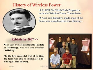
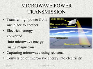
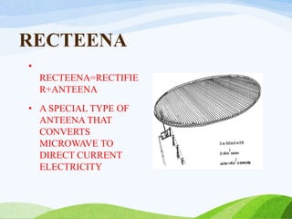
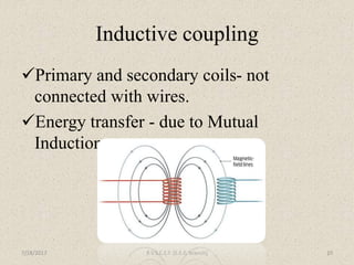
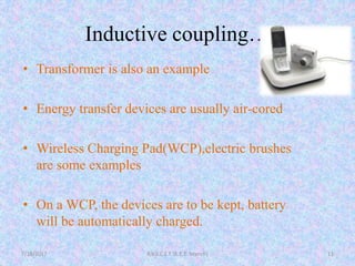
PRESENTED BY:-
1.ANKIT KUMAR 10ENG238223548
2.VIKASH KUMAR 10ENG238223524
3.PANKAJ KR. MEHRA 10ENG238223537
4.RAKESH KUMAR 10ENG238223570
GUIDED BY :- PRO.VIKRAM SAXENA
7/18/2017 R.V.S.C.E.T. (E.E.E. branch) 1
7/18/2017R.V.S.C.E.T. (E.E.E. branch)2
Witricity is nothing but wireless electricity.
Transmission of electrical energy from one
object to another without the use of wires is
called Witricity.
Because of Witricity some of the devices won’t
require batteries to operate .
History of Wireless Power:
 In 1899, Sir Nikola Tesla Proposed a
method of Wireless Power Transmission.
 As it is in Radiative mode, most of the
Power was wasted and has less efficiency.
The team from Massachusetts Institute
of Technology, who call their invention
‘WiTricity‘.
In the first successful trial of its kind,
the team was able to illuminate a 60-
watt light bulb 7ft away.
7/18/2017 R.V.S.C.E.T. (E.E.E. branch) 3
Types of wireless energy transfer
techniques are:-
Short range– Inductive coupling
Mid range– Resonance Inductive coupling
Long range-Microwave Transmission
7/18/2017 R.V.S.C.E.T. (E.E.E. branch) 4
MICROWAVE POWER
TRANSMISSION
• Transfer high power from
one place to another
• Electrical energy
converted
into microwave energy
using magnetron
• Capturing microwave using recteena
• Conversion of microwave energy into electricity
7/18/2017 R.V.S.C.E.T. (E.E.E. branch) 5
LASER POWER TRANSMISSION
* LASER highly directional and coherent
* But, gets attenuated if obstacle between source
and load
7/18/2017 R.V.S.C.E.T. (E.E.E. branch) 6
RECTEENA
•
RECTEENA=RECTIFIE
R+ANTEENA
• A SPECIAL TYPE OF
ANTEENA THAT
CONVERTS
MICROWAVE TO
DIRECT CURRENT
ELECTRICITY
ORBITTING SATELLITE -COLLECTS
SOLAR ENERGY ON SPACE
ADVANTAGES- HIGHER COLLECTION
RATE EXPOSED 24 hr/day
DISADVANTAGES- HIGH COST
EXTRA COST OF MAINTENANCE
MAGNETRON
• A CAVITY
MEGNETRON
IS HIGH
POWER
VACCUM
TUBE
• GENERATES
MICROWAVE
S USING
INTERACTIO
N OF
STREAM OF
ELECTRONS
Inductive coupling
Primary and secondary coils- not
connected with wires.
Energy transfer - due to Mutual
Induction.
7/18/2017 R.V.S.C.E.T. (E.E.E. branch) 10
Inductive coupling…
• Transformer is also an example
• Energy transfer devices are usually air-cored
• Wireless Charging Pad(WCP),electric brushes
are some examples
• On a WCP, the devices are to be kept, battery
will be automatically charged.
7/18/2017 R.V.S.C.E.T. (E.E.E. branch) 11
Resonance Inductive Coupling(RIC)
7/18/2017 R.V.S.C.E.T. (E.E.E. branch)
Combination of inductive coupling and
resonance
Resonance makes two objects interact
very strongly
12
How resonance in RIC?
• Coil provides the inductance
• Capacitor is connected parallel to the coil
• Energy will be shifting back and forth
between magnetic field surrounding the
coil and electric field around the capacitor
• High resonant frequency
7/18/2017 R.V.S.C.E.T. (E.E.E. branch) 13
RIC vs. inductive coupling
• RIC is highly efficient
• RIC has much greater range than inductive
coupling
• RIC is directional when compared to inductive
coupling
• RIC can be one-to-many. But usually inductive
coupling is one-to-one
• Devices using RIC technique are highly portable
7/18/2017R.V.S.C.E.T. (E.E.E. branch)14
AC
MAIN
S
POWER
AMPLIFIER
FILTER
/
INVERTE
R
AC / DC
RECTIFIER
AC-DC
/RF
CONVERT
ER
COMPLETE BLOCK DIAGRAM
PRIMARY
COIL
SECONDRY
COILLOAD
7/18/2017R.V.S.C.E.T. (E.E.E. branch)15
FREQUENCY GENERATION BY FREQUENCY
TRANSFORMER
7/18/2017R.V.S.C.E.T. (E.E.E. branch)
16
TRANSMITTER CIRCUIT:-
7/18/2017 R.V.S.C.E.T. (E.E.E. branch) 17
RECEIVER CIRCUIT:-
7/18/2017 R.V.S.C.E.T. (E.E.E. branch) 18
SPECTRUM USED IN W.P.T.
7/18/2017R.V.S.C.E.T. (E.E.E. branch)19
OUR SIMULATION WORK:-
7/18/2017 R.V.S.C.E.T. (E.E.E. branch) 20
LATEST WORK at KAIST on WPT
7/18/2017R.V.S.C.E.T. (E.E.E. branch)21
This is a simulation result of magnetic flux lines of DCRS coil
configuration
7/18/2017R.V.S.C.E.T. (E.E.E. branch)
22
– Electric automobile charging
– Consumer electronics
– Industrial purposes
Applications:-
7/18/2017 R.V.S.C.E.T. (E.E.E. branch) 23
USES IN TELEVISION
7/18/2017 R.V.S.C.E.T. (E.E.E. branch) 24
USES IN AUTOMOBILE
7/18/2017 R.V.S.C.E.T. (E.E.E. branch) 25
USES IN TOOTHBRUSH
7/18/2017 R.V.S.C.E.T. (E.E.E. branch) 26
IN ROBOTS
Eliminating the need for disposable batteries or a
power cord connecting the helmet
7/18/2017 R.V.S.C.E.T. (E.E.E. branch) 27
Advantages of WITRICITY
• No wires
• Highly Resonent strong coupling provides high Efficiency over Distance
• Energy transfer via magnetic near field can penetrate and wrap arround obstacle
• Non –Radiative energy transfer is safe for people and animals
• Scable Design Enables solution from milli watts to kilowatts
• Maintenance cost is less
• Lower Frequency Operation
• Practical for short Distance
7/18/2017R.V.S.C.E.T. (E.E.E. branch)28
Disadvantages
• Distance constraint
• High power Loss
• Non directionality
• Field strengths have to be under safety levels
• Initial cost is high
• In RIC, tuning is difficult
7/18/2017 R.V.S.C.E.T. (E.E.E. branch) 29
Our achievement :-
7/18/2017R.V.S.C.E.T. (E.E.E. branch)30
DISTANCE IN CENTIMETER
Powerinmilliwatt
REFRENCES:-
a. http://www.wirelesspowerconsortium.com
b. http://www.witricity.com
c. Dr. Morris Kesler WiTricity Corporation” Highly Resonant Wireless
Power Transfer:Safe, Efficient, and over Distance”
d. wikipedia.com
e. Howstuffwork.com
f. www.google.com
7/18/2017 R.V.S.C.E.T. (E.E.E. branch) 31
Thank you !

Wireless power transfer

  • 1.
    PRESENTED BY:- 1.ANKIT KUMAR10ENG238223548 2.VIKASH KUMAR 10ENG238223524 3.PANKAJ KR. MEHRA 10ENG238223537 4.RAKESH KUMAR 10ENG238223570 GUIDED BY :- PRO.VIKRAM SAXENA 7/18/2017 R.V.S.C.E.T. (E.E.E. branch) 1
  • 2.
    7/18/2017R.V.S.C.E.T. (E.E.E. branch)2 Witricityis nothing but wireless electricity. Transmission of electrical energy from one object to another without the use of wires is called Witricity. Because of Witricity some of the devices won’t require batteries to operate .
  • 3.
    History of WirelessPower:  In 1899, Sir Nikola Tesla Proposed a method of Wireless Power Transmission.  As it is in Radiative mode, most of the Power was wasted and has less efficiency. The team from Massachusetts Institute of Technology, who call their invention ‘WiTricity‘. In the first successful trial of its kind, the team was able to illuminate a 60- watt light bulb 7ft away. 7/18/2017 R.V.S.C.E.T. (E.E.E. branch) 3
  • 4.
    Types of wirelessenergy transfer techniques are:- Short range– Inductive coupling Mid range– Resonance Inductive coupling Long range-Microwave Transmission 7/18/2017 R.V.S.C.E.T. (E.E.E. branch) 4
  • 5.
    MICROWAVE POWER TRANSMISSION • Transferhigh power from one place to another • Electrical energy converted into microwave energy using magnetron • Capturing microwave using recteena • Conversion of microwave energy into electricity 7/18/2017 R.V.S.C.E.T. (E.E.E. branch) 5
  • 6.
    LASER POWER TRANSMISSION *LASER highly directional and coherent * But, gets attenuated if obstacle between source and load 7/18/2017 R.V.S.C.E.T. (E.E.E. branch) 6
  • 7.
    RECTEENA • RECTEENA=RECTIFIE R+ANTEENA • A SPECIALTYPE OF ANTEENA THAT CONVERTS MICROWAVE TO DIRECT CURRENT ELECTRICITY
  • 8.
    ORBITTING SATELLITE -COLLECTS SOLARENERGY ON SPACE ADVANTAGES- HIGHER COLLECTION RATE EXPOSED 24 hr/day DISADVANTAGES- HIGH COST EXTRA COST OF MAINTENANCE
  • 9.
    MAGNETRON • A CAVITY MEGNETRON ISHIGH POWER VACCUM TUBE • GENERATES MICROWAVE S USING INTERACTIO N OF STREAM OF ELECTRONS
  • 10.
    Inductive coupling Primary andsecondary coils- not connected with wires. Energy transfer - due to Mutual Induction. 7/18/2017 R.V.S.C.E.T. (E.E.E. branch) 10
  • 11.
    Inductive coupling… • Transformeris also an example • Energy transfer devices are usually air-cored • Wireless Charging Pad(WCP),electric brushes are some examples • On a WCP, the devices are to be kept, battery will be automatically charged. 7/18/2017 R.V.S.C.E.T. (E.E.E. branch) 11
  • 12.
    Resonance Inductive Coupling(RIC) 7/18/2017R.V.S.C.E.T. (E.E.E. branch) Combination of inductive coupling and resonance Resonance makes two objects interact very strongly 12
  • 13.
    How resonance inRIC? • Coil provides the inductance • Capacitor is connected parallel to the coil • Energy will be shifting back and forth between magnetic field surrounding the coil and electric field around the capacitor • High resonant frequency 7/18/2017 R.V.S.C.E.T. (E.E.E. branch) 13
  • 14.
    RIC vs. inductivecoupling • RIC is highly efficient • RIC has much greater range than inductive coupling • RIC is directional when compared to inductive coupling • RIC can be one-to-many. But usually inductive coupling is one-to-one • Devices using RIC technique are highly portable 7/18/2017R.V.S.C.E.T. (E.E.E. branch)14
  • 15.
    AC MAIN S POWER AMPLIFIER FILTER / INVERTE R AC / DC RECTIFIER AC-DC /RF CONVERT ER COMPLETEBLOCK DIAGRAM PRIMARY COIL SECONDRY COILLOAD 7/18/2017R.V.S.C.E.T. (E.E.E. branch)15
  • 16.
    FREQUENCY GENERATION BYFREQUENCY TRANSFORMER 7/18/2017R.V.S.C.E.T. (E.E.E. branch) 16
  • 17.
  • 18.
  • 19.
    SPECTRUM USED INW.P.T. 7/18/2017R.V.S.C.E.T. (E.E.E. branch)19
  • 20.
    OUR SIMULATION WORK:- 7/18/2017R.V.S.C.E.T. (E.E.E. branch) 20
  • 21.
    LATEST WORK atKAIST on WPT 7/18/2017R.V.S.C.E.T. (E.E.E. branch)21 This is a simulation result of magnetic flux lines of DCRS coil configuration
  • 22.
  • 23.
    – Electric automobilecharging – Consumer electronics – Industrial purposes Applications:- 7/18/2017 R.V.S.C.E.T. (E.E.E. branch) 23
  • 24.
    USES IN TELEVISION 7/18/2017R.V.S.C.E.T. (E.E.E. branch) 24
  • 25.
    USES IN AUTOMOBILE 7/18/2017R.V.S.C.E.T. (E.E.E. branch) 25
  • 26.
    USES IN TOOTHBRUSH 7/18/2017R.V.S.C.E.T. (E.E.E. branch) 26
  • 27.
    IN ROBOTS Eliminating theneed for disposable batteries or a power cord connecting the helmet 7/18/2017 R.V.S.C.E.T. (E.E.E. branch) 27
  • 28.
    Advantages of WITRICITY •No wires • Highly Resonent strong coupling provides high Efficiency over Distance • Energy transfer via magnetic near field can penetrate and wrap arround obstacle • Non –Radiative energy transfer is safe for people and animals • Scable Design Enables solution from milli watts to kilowatts • Maintenance cost is less • Lower Frequency Operation • Practical for short Distance 7/18/2017R.V.S.C.E.T. (E.E.E. branch)28
  • 29.
    Disadvantages • Distance constraint •High power Loss • Non directionality • Field strengths have to be under safety levels • Initial cost is high • In RIC, tuning is difficult 7/18/2017 R.V.S.C.E.T. (E.E.E. branch) 29
  • 30.
    Our achievement :- 7/18/2017R.V.S.C.E.T.(E.E.E. branch)30 DISTANCE IN CENTIMETER Powerinmilliwatt
  • 31.
    REFRENCES:- a. http://www.wirelesspowerconsortium.com b. http://www.witricity.com c.Dr. Morris Kesler WiTricity Corporation” Highly Resonant Wireless Power Transfer:Safe, Efficient, and over Distance” d. wikipedia.com e. Howstuffwork.com f. www.google.com 7/18/2017 R.V.S.C.E.T. (E.E.E. branch) 31
  • 32.