

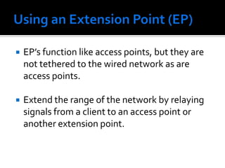
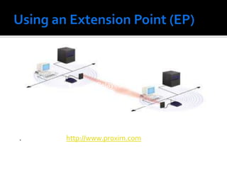
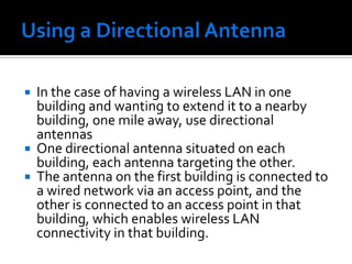
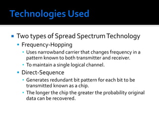
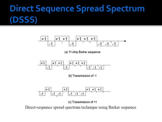
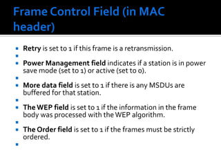
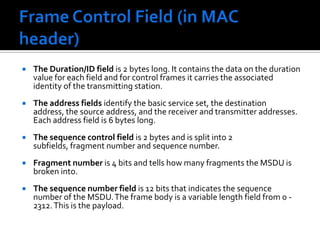
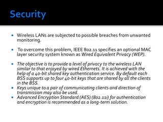
![Direct Sequence Spread Spectrum (DSSS)The IEEE 802.11 uses a simple 11-chip Barker sequence B11 [-1, +1, -1, -1, +1, -1, -1, -1, +1, +1, +1] with QPSK or BPSK modulationThe Barker sequence provides good immunity against interference and noise as well as some protection against multi-path propagation.The number of chips that represent a bit is the spreading ratio. The higher the spreading ratio, the more the signal is resistant to interference. The lower the spreading ratio, the more bandwidth is available to the user.The FCC dictates that the spreading ratio must be more than ten. Most products have a spreading ratio of less than 20 and the new IEEE 802.11 standard requires a spreading ratio of eleven.](https://image.slidesharecdn.com/wirelesslan-110414110628-phpapp01/85/Wireless-lan-39-320.jpg)

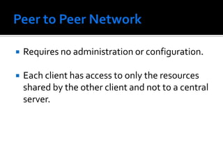
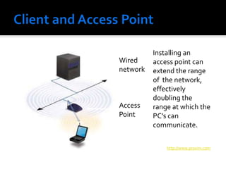
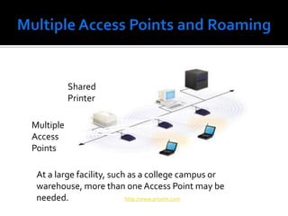
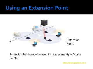
The document discusses wireless local area networks (WLANs) and their advantages over wired networks, including mobility, ease of installation, flexibility, and reduced costs. It describes various WLAN configurations including peer-to-peer networks, client/access point networks, and networks using multiple access points or extension points. The document also covers WLAN standards, hardware components, connection processes, capacity, and technologies used including spread spectrum techniques like direct sequence spread spectrum (DSSS) and frequency hopping spread spectrum (FHSS).


