Downloaded 44 times
![MT31C-I
13
4. Databases
5. Security Mechanism
6. Gateway consisting of MTSO or MSC
Mobile Subscriber Units (MSUs) or Mobile station (MS)
The mobile subscriber unit consists of a control unit and a transceiver that
transmits and receives radio transmissions to and from a cell site and an
antenna system. Whenever a mobile unit wants to setup a call, it contacts the
cell site of the particular cell in which it exists at that time. The cell site
consists of control unit, antennas, power plant and data terminals. The cell
site is in fact acting as an interface to the MTSO. After the mobile unit
contacts the cell site, the cell site in turn contacts the MTSO which processes
the call further depending on whether it is a mobile to mobile call or mobile to
fixed station call.
For example, in GSM networks, the mobile station will consist of the Mobile
equipment (ME) and the SIM card.
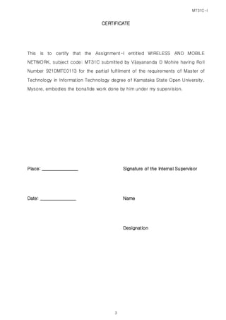
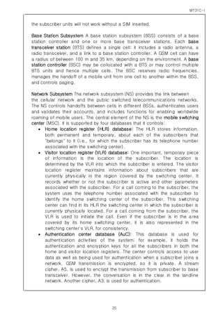
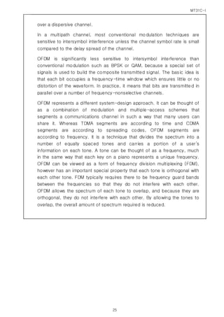
Air Interface standard
Figure 5 Air Interface
Common Air Interface: A Standard that defines Communication
between a Base Station and Mobile
Specifies Four Channels [Voice Channels and Control / Setup
Channels]](https://image.slidesharecdn.com/wirelessandmobilenetworkassigniver2-150413230353-conversion-gate01/85/M-Tech-WIRELESS-AND-MOBILE-NETWORK-Assignment-I-13-320.jpg)
![MT31C-I
21
Equipment identity register database (EIR): The EIR keeps track of the
type of equipment that exists at the mobile station. It also plays a role in
security (e.g., blocking calls from stolen mobile stations and preventing
use of the network by stations that have not been approved).
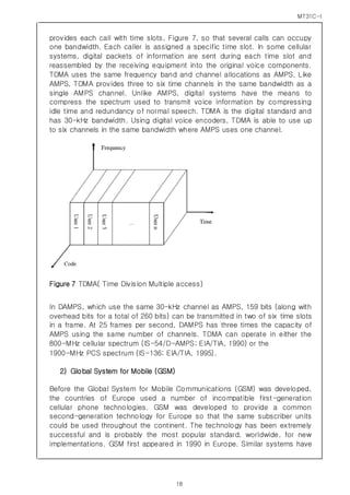
The Operation and Support System (OSS) The operations and maintenance
center (OMC) is connected to all equipment in the switching system and to the
BSC through MSC. The implementation of the OMC is called the operation and
support system (OSS). The OSS is the functional entity from which the network
operator monitors and controls the system. The purpose of OSS is to offer the
customer cost-effective support for centralized, regional and local operational
and maintenance activities that are required for a GSM network. An important
function of OSS is to provide a network overview and support the maintenance
activities of different operation and maintenance organizations.
3) Personal Communication Services (PCS)
The future of telecommunications includes PCS. PCS at 1900 MHz (PCS 1900)
is the North American implementation of digital cellular system (DCS) 1800
(GSM). Trial networks were operational in the United States by 1993, and in
1994 the Federal Communications Commission (FCC) began spectrum
auctions. As of 1995, the FCC auctioned commercial licenses. In the PCS
frequency spectrum, the operator's authorized frequency block contains a
definite number of channels. The frequency plan assigns specific channels to
specific cells, following a reuse pattern that restarts with each nth cell. The
uplink and downlink bands are paired mirror images. As with AMPS, a channel
number implies one uplink and one downlink frequency (e.g., Channel 512 =
1850.2-MHz uplink paired with 1930.2-MHz downlink).
Personal Communication Services is a system, very similar to Cellular Phone
Service with great emphasis on personal services (such as Paging, Caller ID,
and E-mail] and mobility. Originated in UK, to improve its competitiveness in
the field. PCS has smaller cell size, therefore, requires more infra-structure.
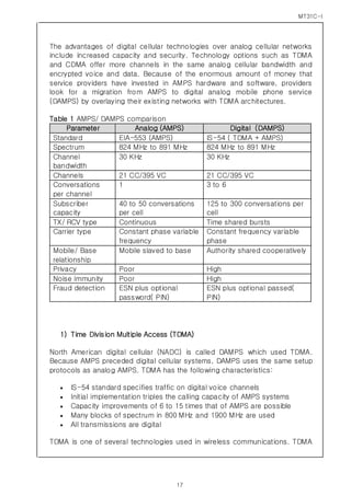
PCS works in 1.85-1.99 GHz band. PCS uses TDMA Technology but with 200
KHz Channel Bandwidth with eight time-slots (as compared to 30 KHz and 3
time-slots used by Digital Cellular Phone System IS-54/IS-136). GSM and
Cellular Digital Packet Data (CDPD) also use PCS Technology.](https://image.slidesharecdn.com/wirelessandmobilenetworkassigniver2-150413230353-conversion-gate01/85/M-Tech-WIRELESS-AND-MOBILE-NETWORK-Assignment-I-21-320.jpg)
![MT31C-I
26
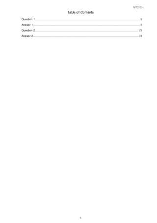
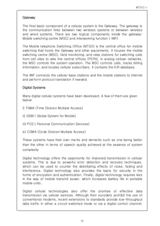
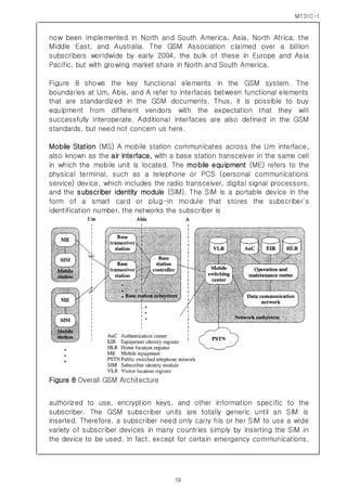
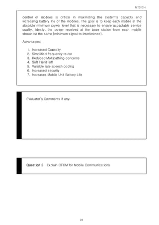
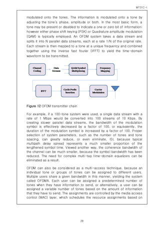
Figure 10 OFDM Tones
The fundamental principle of the OFDM system is to decompose the high
rate data stream (bandwidth = W) into N lower rate data streams and then to
transmit them simultaneously over a large number of subcarriers. A
sufficiently high value of N makes the individual bandwidth (W/N) of
subcarriers narrower than the coherence bandwidth (Bc) of the channel.
The individual subcarriers as such experience flat fading only, and this can
be compensated using a trivial frequency domain single- tap equalizer. The
choice of individual subcarrier is such that they are orthogonal to each
other, which allows for the overlapping of subcarriers because the
orthogonality ensures the separation of subcarriers at the receiver end. This
approach results in a better spectral efficiency than that of FDMA systems,
where no spectral overlap of carriers is allowed.
The spectral efficiency of an OFDM system is shown pictorially in Figure 11,
which illustrates the difference between the conventional nonoverlapping
multicarrier technique (such as FDMA) and the overlapping multicarrier
modulation technique [such as discrete multitone (DMT), OFDM, and the
like]. As shown in Figure 11, the overlapping multicarrier modulation
technique can achieve superior bandwidth utilization. To realize the benefits
of the overlapping](https://image.slidesharecdn.com/wirelessandmobilenetworkassigniver2-150413230353-conversion-gate01/85/M-Tech-WIRELESS-AND-MOBILE-NETWORK-Assignment-I-26-320.jpg)

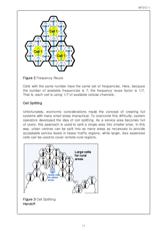
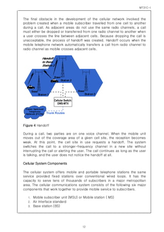
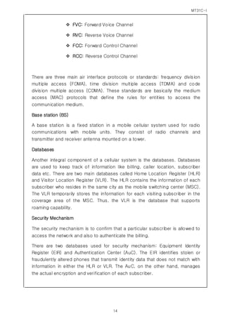
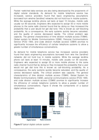
This document discusses mobile communication principles and digital cellular systems. It describes the key components of a cellular system including cells, clusters, frequency reuse, and handoffs. It also explains the components of a cellular network such as mobile stations, base stations, databases, security mechanisms, and gateways. Finally, it provides an overview of digital cellular technologies including TDMA, GSM, PCS, and CDMA systems and how they improve capacity over early analog systems.