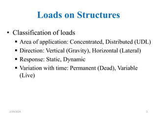
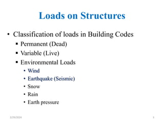
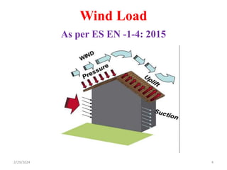
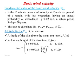
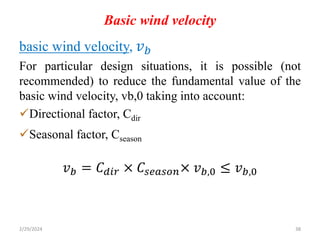
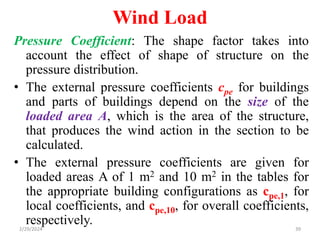
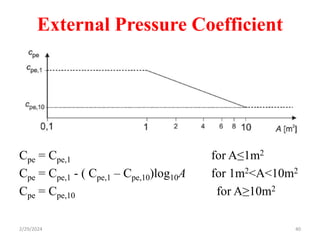
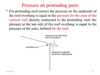
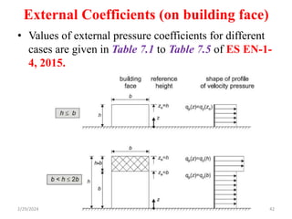
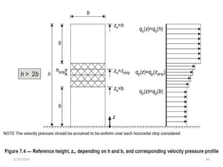
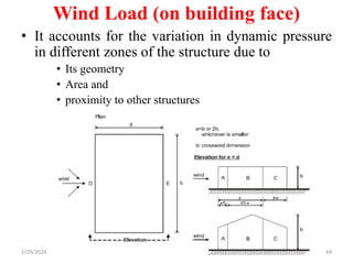
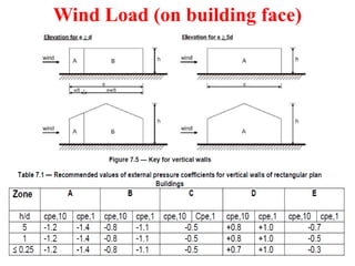
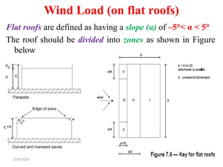
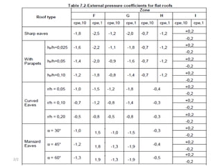
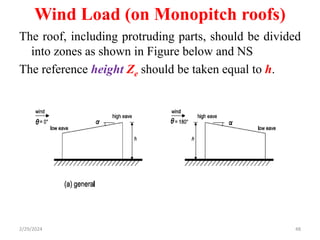
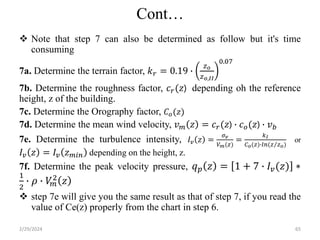
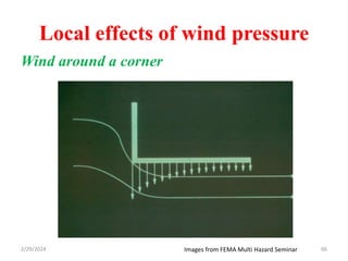
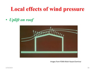
Chapter 2 – Loads and Load
Effects
(Part I:Wind Load Analysis)
1
2/29/2024
Loads on Structures
• Classification of loads
 Area of application: Concentrated, Distributed (UDL)
 Direction: Vertical (Gravity), Horizontal (Lateral)
 Response: Static, Dynamic
 Variation with time: Permanent (Dead), Variable
(Live)
2
2/29/2024
Loads on Structures
• Classification of loads in Building Codes
 Permanent (Dead)
 Variable (Live)
 Environmental Loads
• Wind
• Earthquake (Seismic)
• Snow
• Rain
• Earth pressure
3
2/29/2024
Wind Load
As per ES EN -1-4: 2015
4
2/29/2024
Wind load
Wind is air in motion.
• Structure deflects or stops the wind, converting the
wind’s kinetic energy into potential energy of
pressure.
• Structure in the wind are subjected to forces which
vary with time and space.
• The wind loads that act on a structure result from
movement of the air against the obstructing surfaces.
• Wind effects induce forces, vibrations, and in some
cases instabilities in the overall structure as well as its
non-structural components.
5
2/29/2024
6
• Wind velocity increases with the power of the structural
height
Wind load
2/29/2024
Cont…
2/29/2024 7
8
Wind load
2/29/2024
Wind load
9
These wind effects depend on:
 the wind speed,
 density of the air,
 shape of the structure
 location and geometry of the structure, and
 vibrational characteristics of the system.
Wind Forces According to ES EN-1-4, 2015
Wind pressure in this section is valid for rigid
surface only and neglects their resonant
vibration.
2/29/2024
Wind Load
Two method of analysis is provided
 The static(simple) procedure:
Only used for structures whose structural properties
do not make them susceptible to Structural
factor(CsCd ≤ 1.2)
 A detailed Dynamic Procedure:
must used for those structures which are likely to be
susceptible to Structural factor(CsCd > 1.2)
 In order to determine Structural Factor CsCd
,Charts and figures can be used (ES EN-1-4-2015
topic 6.2 or Appendices D-fig D.1 to D.5)
10
2/29/2024
11
Wind Load
2/29/2024
Cont…
2/29/2024 12
Cont…
• Flexible structures (e.g. tall buildings and long span
bridges ) are particularly sensitive to dynamic
interaction phenomena thus Theory of aero elasticity
must be embedded in the structural design.
• For ordinary buildings with conventional structural
systems, with “simple” shape and “small” extension
designers are allowed to use equivalent static forces
to represent the actual effects of the turbulent wind.
2/29/2024 13
Wind load (Simple procedure)
Wind Pressure: The external and internal wind
pressures are given as:
We=qp(ze )*Cpe
Wi=qp(zi )*Cpi
Wnet=We -Wi
• Where: We , Wi and Wnet are the external, internal and
net wind pressures;
(ze ) and (zi ) are reference height for the external
and internal pressure;
Cpe and Cpi are the external and internal pressure
coefficients.
14
2/29/2024
Mean wind Velocity(VM(z))
The mean wind velocity: VM(z) at a height z above the
terrain depends on the terrain roughness, orography
and the basic wind velocity, Vb, and should be
determined using Expression:
vM(z) = cr(z)*co(z)*Vb
Where:
-cr(z) is the roughness factor,
-co(z) is the orography factor, taken as 1.0 (unless
otherwise specified in ES EN 1-4-2015-4.3.3 or use
the procedure on Annex A.3)
2/29/2024 15
Terrain Roughness(cr(z))
The roughness factor, cr(z) accounts for the
variability of the mean wind velocity at the site of the
structure due to:
 the height above ground level
 the ground roughness of the terrain upwind of the
structure in the wind direction considered.
The recommended procedure for the determination
of the roughness factor at height z is given by
Expression:
2/29/2024 16
Cont…
where:
z0 is the roughness length
kr terrain factor depending on the roughness length z0.
The terrain factor, kr accounts for the terrain effect on the
mean wind velocity.
Where:
z0,II 0.05 m ( for terrain category II, Table 4.1)
zmin is the minimum height defined in Table 4.1
zmax is to be taken as 200 m,
z0, zmin depend on the terrain category. Recommended
values are given in Table 4.1
2/29/2024 17
2/29/2024 18
Terrain Orography(co(z))
The Orography factor co(z) Where orography
(e.g. hills, cliffs etc.) increases wind velocities by
more than 5% the effects should be taken into
account using the orography factor cO (z).
At isolated hills and ridges or cliffs and
escarpments different wind velocities occur
dependent on the upstream slope Φ=H/Lu in the
wind direction, where the height H and the length
Lu are defined in Figure below.
2/29/2024 19
2/29/2024 20
The largest increase of the wind velocities occurs near the
top of the slope and is determined from the orography factor
co, see Figure A.1. The slope has no significant effect on the
standard deviation of the turbulence.
Cont…
The orography factor, Co(z)=Vm/Vmf
accounts for the increase of mean wind speed
over isolated hills and escarpments (not
undulating and mountainous regions).
It is related to the wind velocity at the base of
the hill or escarpment.
2/29/2024 21
Cont…
The effects of orography should be taken into
account in the following situations:
a) For sites on upwind slopes of hills and ridges:
where 0.05 < Φ ≤ 0.3 and |x| ≤ Lu/2
b) For sites on downwind slopes of hills and ridges:
where Φ < 0.3 and x < Ld/2
where Φ ≥ 0.3 and x < 1.6 H
c) For sites on upwind slopes of cliffs and escarpments:
where 0.05 < Φ ≤ 0.3 and |x| ≤ Lu/2
d) For sites on downwind slopes of cliffs and escarpments:
where Φ < 0.3 and x< 1.5 Le
where Φ ≥ 0.3 and x< 5 H
2/29/2024 22
Cont…
It is defined by:
Co= 1 for Φ < 0.05
Co= 1+ 2 *s *Φ for 0.05 < Φ < 0.3
Co= 1+ 0.6 *s for Φ > 0.3
where:
s is the orographic location factor, to be obtained from Figure
A.2 or Figure A.3 scaled to the length of the effective upwind
slope length, Le
Φ is the upwind slope H/Lu in the wind direction (see Figure A.2
and Figure A.3)
Le is the effective length of the upwind slope, defined in Table
A.2
Lu is the actual length of the upwind slope in the wind direction
Ld is the actual length of the downwind slope in the wind
direction
2/29/2024 23
Cont…
H is the effective height of the feature
x is the horizontal distance of the site from the top
of the crest
z is the vertical distance from the ground level of
the site
Table A.2 Values of the effective length, 𝐿𝑒
2/29/2024 24
Type of slope (Φ = H/Lu)
Shallow (0.05 < Φ < 0.3) Steep (Φ > 0.3)
Le = Lu Le = H/0.3
2/29/2024 25
Cliffs and Escarpments
2/29/2024 26
Hills and ridges
basic wind pressure, qb
• The dynamic pressure due to the wind is the
kinetic energy per unit volume of the flowing air
𝑞𝑏 =
1
2
𝜌𝑎𝑖𝑟 ∗ 𝑣𝑏
2
The density of the air is assumed to be ρair= 1.25 kg/m3
• This is only a “nominal” or “reference” value of
the wind pressure, as the above equation
assumes a uniform, laminar flow of the air, and
does not account for effects of the turbulence
and variation with height.
2/29/2024 27
The peak velocity pressure qp(z)
• The basic value of wind pressure qb can be
transformed into the peak value qp(z) , varying with
the height z, taking into account:
The roughness of the surrounding terrain;
The site’s proximity to the coast;
How far the site is located within a town (if
applicable)
• This is done with either two methods:
“proximity to shore line & site within town”
exposure coefficient 𝑐𝑒(𝑧);
“short term variation ” turbulence intensity
𝐼𝑣 (𝑧) and mean wind velocity 𝑣𝑚 (𝑧) ;
2/29/2024 28
Cont…
𝑞𝑝 𝑧 = 1 + 7 ∙ 𝐼𝑣(𝑧) ∙
1
2
∙ 𝜌 ∙ 𝑉
𝑚
2 𝑧 = 𝑐𝑒(𝑧) ∙ 𝑞𝑏
The exposure factor Ce(z)
For flat terrain with Co(z) =1.0 and KI=1.0, the
exposure coefficient can be read from the chart shown
below depending on the terrain category and reference
height of the structure.
2/29/2024 29
The exposure factor Ce(z)
2/29/2024 30
The peak velocity pressure qp(z)
31
The peak velocity pressure qp(z) at height z,
which includes mean and short-term velocity
fluctuations, should be determined.
Where:
ρ is the air density, which depends on the altitude,
temperature and barometric pressure to be expected in the
region during wind storms (recom. value is ρ=1.25kg/m3).
ce(z) is the exposure factor given in Expression:
.
2/29/2024
The peak velocity pressure qp(z)
qb is the basic velocity pressure given in
Expression:
Where
Vb is the basic wind velocity, defined as a function of wind
direction and time of year at 10 m above ground of terrain
category II.
Vb,0 is the fundamental value of the basic wind velocity (Vb,0
= 22m/s from the old code & 28m/s in a new code)
Cdir is the directional factor(The recommended value is 1.0)
Cseason is the season factor(The recommended value is 1.0)
32
2/29/2024
2/29/2024 33
Wind Velocity
• The wind velocity and the velocity pressure are
composed of a mean and a fluctuating component.
• The mean wind velocity 𝑣𝑚 should be determined
from the basic wind velocity vb which depends on the
wind climate and the height variation of the wind
determined from the terrain roughness and orography.
• The fluctuating component of the wind is represented
by the turbulence intensity.
2/29/2024 34
Mean wind velocity,𝒗𝒎
• The mean wind velocity Vm(z) at a height z above the
terrain depends on the terrain roughness and orography and
on the basic wind velocity, vb, and should be determined
using: 𝑣𝑚 𝑧 = 𝑐𝑟(𝑧) ∙ 𝑐𝑜(𝑧) ∙ 𝑣𝑏
Where: 𝑐𝑟 𝑧 𝑖𝑠 𝑡ℎ𝑒 𝑟𝑜𝑢𝑔ℎ𝑛𝑒𝑠𝑠 𝑓𝑎𝑐𝑡𝑜𝑟
𝑐𝑜(𝑧) is the orography factor.
2/29/2024 35
Turbulence intensity, Iv
• The turbulence intensity Iv(z) at height z is defined as the standard
deviation of the turbulence divided by the mean wind velocity.
• Wind turbulence is a phenomenon of disturbance of air flow.
Where:
KI is the turbulence factor. The recommended value is 1.0.
Co(z) is the orography factor.
z0 is the roughness length.
zmin is the minimum height.
2/29/2024 36
Basic wind velocity
Fundamental value of the basic wind velocity, Vb,o
• Is the 10 minute mean wind velocity at 10m above ground,
of a terrain with low vegetation, having an annual
probability of exceedance p=0.02 (i.e. a return period
R=1/p= 50 years.
• This can be calculated as: 𝑣𝑏,0= 𝑣𝑏,𝑚𝑎𝑝 × 𝐶𝑎𝑙𝑡
Altitude factor Calt it depends on
 Altitude of the site above the mean sea level , A(m)
 Reference height of the structure, zs (m)
𝐶𝑎𝑙𝑡 =
1 + 0.001𝐴, 𝑧𝑠 ≤ 10𝑚
1 + 0.001𝐴 ∙
10
𝑧𝑠
0.2
, 𝑧𝑠 > 10𝑚
2/29/2024 37
Basic wind velocity
basic wind velocity, 𝑣𝑏
For particular design situations, it is possible (not
recommended) to reduce the fundamental value of the
basic wind velocity, vb,0 taking into account:
Directional factor, Cdir
Seasonal factor, Cseason
𝑣𝑏 = 𝐶𝑑𝑖𝑟 × 𝐶𝑠𝑒𝑎𝑠𝑜𝑛× 𝑣𝑏,0 ≤ 𝑣𝑏,0
2/29/2024 38
Wind Load
Pressure Coefficient: The shape factor takes into
account the effect of shape of structure on the
pressure distribution.
• The external pressure coefficients cpe for buildings
and parts of buildings depend on the size of the
loaded area A, which is the area of the structure,
that produces the wind action in the section to be
calculated.
• The external pressure coefficients are given for
loaded areas A of 1 m2 and 10 m2 in the tables for
the appropriate building configurations as cpe,1, for
local coefficients, and cpe,10, for overall coefficients,
respectively. 39
2/29/2024
Cpe = Cpe,1 for A≤1m2
Cpe = Cpe,1 - ( Cpe,1 – Cpe,10)log10A for 1m2<A<10m2
Cpe = Cpe,10 for A≥10m2
40
External Pressure Coefficient
2/29/2024
Pressure on protruding parts
• For protruding roof corners the pressure on the underside of
the roof overhang is equal to the pressure for the zone of the
vertical wall directly connected to the protruding roof; the
pressure at the top side of the roof overhang is equal to the
pressure of the zone, defined for the roof.
2/29/2024 41
External Coefficients (on building face)
• Values of external pressure coefficients for different
cases are given in Table 7.1 to Table 7.5 of ES EN-1-
4, 2015.
42
2/29/2024
2/29/2024 43
44
Wind Load (on building face)
• It accounts for the variation in dynamic pressure
in different zones of the structure due to
• Its geometry
• Area and
• proximity to other structures
2/29/2024
Wind Load (on building face)
45
2/29/2024
Wind Load (on flat roofs)
Flat roofs are defined as having a slope (α) of –5°< α < 5°
The roof should be divided into zones as shown in Figure
below
46
2/29/2024
2/29/2024 47
Wind Load (on Monopitch roofs)
The roof, including protruding parts, should be divided
into zones as shown in Figure below and NS
The reference height Ze should be taken equal to h.
48
2/29/2024
Wind Load (on Monopitch roofs)
49
2/29/2024
Wind Load (on Monopitch roofs)
• External pressure coefficients for mono pitch roof for θ=0° & 180°
2/29/2024 50
Wind Load (on Monopitch roofs)
• External pressure coefficients for mono pitch roof for θ=90°
2/29/2024 51
Wind Load (on Duo pitch roofs)
The roof, including protruding parts, should be divided
into zones as shown in Figure below and NS
The reference height Ze should be taken equal to h.
52
2/29/2024
Wind Load (on Duo pitch roofs)
53
2/29/2024
Wind Load (on Duo pitch roofs)
54
2/29/2024
Wind Load (on Duo pitch roofs)
55
2/29/2024
Wind Load (on Hipped roofs)
The roof, including protruding parts, should be divided
into zones as shown in Figure below and NS
The reference height Ze should be taken equal to h.
56
2/29/2024
Wind Load (on Hipped pitch roofs)
57
2/29/2024
Wind Load (on Hipped pitch roofs)
• External pressure coefficients for hipped pitch roof for θ=0° & 90°
2/29/2024 58
Internal pressure Coefficient Cpi
• The internal pressure coefficient, cpi, depends on the size
and distribution of the openings in the building envelope.
• For a building with a dominant face:
When the area of the openings at the dominant face is
twice the area of the openings in the remaining faces,
𝑐𝑝𝑖 = 0.75 ∙ 𝑐𝑝𝑒
When the area of the openings at the dominant face is
at least 3 times the area of the openings in the remaining
faces,
𝑐𝑝𝑖 = 0.90 ∙ 𝑐𝑝𝑒
Where: 𝑐𝑝𝑒 is the value for the external pressure coefficient at
the openings in the dominant face. When these openings are
located in zones with different values of external pressures an area
weighted average value of 𝑐𝑝𝑒 should be used.
2/29/2024 59
Internal pressure Coefficient Cpi
• For a building with out a dominant face it is a function of the
ratio of the height and the depth of the building, h/d, and the
opening ratio μ for each wind direction θ.
2/29/2024 60
Internal pressure Coefficient Cpi
𝜇 =
𝑎𝑟𝑒𝑎 𝑜𝑓 𝑜𝑝𝑒𝑛𝑖𝑛𝑔𝑠 𝑤ℎ𝑒𝑟𝑒 𝑐𝑝𝑒 𝑖𝑠 𝑛𝑒𝑔𝑎𝑡𝑖𝑣𝑒 𝑜𝑟 0.0
𝑎𝑟𝑒𝑎 𝑜𝑓 𝑎𝑙𝑙 𝑜𝑝𝑒𝑛𝑛𝑖𝑛𝑔
• Where it is not possible, or not considered justified, to estimate
μ for a particular case then cpi should be taken as the more
onerous of: 𝑐𝑝𝑖 = +0.20 or 𝑐𝑝𝑖 = −0.30
 Internal and external pressures shall be considered to act at the
same time. The worst combination of external and internal
pressures shall be considered for every combination of
possible openings and other leakage paths.
2/29/2024 61
Wind load
Net pressure: the difference of the pressures (external
and internal) on each surface due account of their signs.
62
2/29/2024
Steps to determine net wind pressure
1. Determine fundamental value of basic wind velocity, 𝑣𝑏,0
=22 m/s or 28 m/s or take it from metrological data.
2. Determine basic wind velocity, 𝑣𝑏 = 𝐶𝑑𝑖𝑟 × 𝐶𝑠𝑒𝑎𝑠𝑜𝑛× 𝑣𝑏,0 ≤
𝑣𝑏,0
3. Determine basic velocity pressure, 𝑞𝑏 =
1
2
𝜌𝑎𝑖𝑟 ∙ 𝑣𝑏
2
4. Determine the building height (Z = Ze or Zi) and the terrain
category of the site where the building is to be built.
5. Assume that the building is to be built on flat terrain so that
the effect of orography and turbulence is not significant.
therefore take orography factor Co(z)=1.0 and turbulence
factor KI=1.0
2/29/2024 63
Cont…
6. Read the value of exposure coefficient, 𝑐𝑒(𝑧) from ES EN
1991:2015 part 4, table 4.2 on page 14.
7. Determine the peak velocity pressure, 𝑞𝑝 𝑧 =
𝑐𝑒(𝑧) ∙ 𝑞𝑏
8. Determine the external pressure coefficients, Cpe. Note that
the procedure to determine Cpe values for vertical walls
differs from that of roofs.
9. Determine the internal pressure coefficients, 𝑐𝑝𝑖
10. Determine the external wind pressure, 𝑊
𝑒 = 𝑞𝑝(𝑧𝑒) ∗ 𝑐𝑝𝑒
11. Determine internal wind pressure, 𝑊𝑖 = 𝑞𝑝(𝑧𝑖) ∙ 𝑐𝑝𝑖
12. Determine the net wind pressure, 𝑊𝑛𝑒𝑡 = 𝑊
𝑒 − 𝑊𝑖
2/29/2024 64
Cont…
 Note that step 7 can also be determined as follow but it's time
consuming
7a. Determine the terrain factor, 𝑘𝑟 = 0.19 ∙
𝑧𝑜
𝑧𝑜,𝐼𝐼
0.07
7b. Determine the roughness factor, 𝑐𝑟(𝑧) depending oh the reference
height, z of the building.
7c. Determine the Orography factor, 𝐶𝑜(𝑧)
7d. Determine the mean wind velocity, 𝑣𝑚 𝑧 = 𝑐𝑟(𝑧) ∙ 𝑐𝑜(𝑧) ∙ 𝑣𝑏
7e. Determine the turbulence intensity, 𝐼𝑣 𝑧 =
𝜎𝑣
𝑉𝑚(𝑧)
=
𝑘𝐼
𝐶𝑜(𝑧)∙𝑙𝑛(𝑧 𝑧𝑜)
or
𝐼𝑣 𝑧 = 𝐼𝑣 𝑧𝑚𝑖𝑛 depending on the height, z.
7f. Determine the peak velocity pressure, 𝑞𝑝 𝑧 = 1 + 7 ∙ 𝐼𝑣(𝑧) ∗
1
2
∙ 𝜌 ∙ 𝑉
𝑚
2 𝑧
 step 7e will give you the same result as that of step 7, if you read the
value of Ce(z) properly from the chart in step 6.
2/29/2024 65
Local effects of wind pressure
Wind around a corner
66
Images from FEMA Multi Hazard Seminar
2/29/2024
67
Local effects of wind pressure
Images from FEMA Multi Hazard Seminar
2/29/2024
• Uplift on roof
68
Local effects of wind pressure
Images from FEMA Multi Hazard Seminar
2/29/2024
69
Local effects of wind pressure
Images from FEMA Multi Hazard Seminar
2/29/2024

Chapter-2- part I- ES EN 1991-Section 4, Wind load.pptx

  • 1.
    Chapter 2 –Loads and Load Effects (Part I:Wind Load Analysis) 1 2/29/2024
  • 2.
    Loads on Structures •Classification of loads  Area of application: Concentrated, Distributed (UDL)  Direction: Vertical (Gravity), Horizontal (Lateral)  Response: Static, Dynamic  Variation with time: Permanent (Dead), Variable (Live) 2 2/29/2024
  • 3.
    Loads on Structures •Classification of loads in Building Codes  Permanent (Dead)  Variable (Live)  Environmental Loads • Wind • Earthquake (Seismic) • Snow • Rain • Earth pressure 3 2/29/2024
  • 4.
    Wind Load As perES EN -1-4: 2015 4 2/29/2024
  • 5.
    Wind load Wind isair in motion. • Structure deflects or stops the wind, converting the wind’s kinetic energy into potential energy of pressure. • Structure in the wind are subjected to forces which vary with time and space. • The wind loads that act on a structure result from movement of the air against the obstructing surfaces. • Wind effects induce forces, vibrations, and in some cases instabilities in the overall structure as well as its non-structural components. 5 2/29/2024
  • 6.
    6 • Wind velocityincreases with the power of the structural height Wind load 2/29/2024
  • 7.
  • 8.
  • 9.
    Wind load 9 These windeffects depend on:  the wind speed,  density of the air,  shape of the structure  location and geometry of the structure, and  vibrational characteristics of the system. Wind Forces According to ES EN-1-4, 2015 Wind pressure in this section is valid for rigid surface only and neglects their resonant vibration. 2/29/2024
  • 10.
    Wind Load Two methodof analysis is provided  The static(simple) procedure: Only used for structures whose structural properties do not make them susceptible to Structural factor(CsCd ≤ 1.2)  A detailed Dynamic Procedure: must used for those structures which are likely to be susceptible to Structural factor(CsCd > 1.2)  In order to determine Structural Factor CsCd ,Charts and figures can be used (ES EN-1-4-2015 topic 6.2 or Appendices D-fig D.1 to D.5) 10 2/29/2024
  • 11.
  • 12.
  • 13.
    Cont… • Flexible structures(e.g. tall buildings and long span bridges ) are particularly sensitive to dynamic interaction phenomena thus Theory of aero elasticity must be embedded in the structural design. • For ordinary buildings with conventional structural systems, with “simple” shape and “small” extension designers are allowed to use equivalent static forces to represent the actual effects of the turbulent wind. 2/29/2024 13
  • 14.
    Wind load (Simpleprocedure) Wind Pressure: The external and internal wind pressures are given as: We=qp(ze )*Cpe Wi=qp(zi )*Cpi Wnet=We -Wi • Where: We , Wi and Wnet are the external, internal and net wind pressures; (ze ) and (zi ) are reference height for the external and internal pressure; Cpe and Cpi are the external and internal pressure coefficients. 14 2/29/2024
  • 15.
    Mean wind Velocity(VM(z)) Themean wind velocity: VM(z) at a height z above the terrain depends on the terrain roughness, orography and the basic wind velocity, Vb, and should be determined using Expression: vM(z) = cr(z)*co(z)*Vb Where: -cr(z) is the roughness factor, -co(z) is the orography factor, taken as 1.0 (unless otherwise specified in ES EN 1-4-2015-4.3.3 or use the procedure on Annex A.3) 2/29/2024 15
  • 16.
    Terrain Roughness(cr(z)) The roughnessfactor, cr(z) accounts for the variability of the mean wind velocity at the site of the structure due to:  the height above ground level  the ground roughness of the terrain upwind of the structure in the wind direction considered. The recommended procedure for the determination of the roughness factor at height z is given by Expression: 2/29/2024 16
  • 17.
    Cont… where: z0 is theroughness length kr terrain factor depending on the roughness length z0. The terrain factor, kr accounts for the terrain effect on the mean wind velocity. Where: z0,II 0.05 m ( for terrain category II, Table 4.1) zmin is the minimum height defined in Table 4.1 zmax is to be taken as 200 m, z0, zmin depend on the terrain category. Recommended values are given in Table 4.1 2/29/2024 17
  • 18.
  • 19.
    Terrain Orography(co(z)) The Orographyfactor co(z) Where orography (e.g. hills, cliffs etc.) increases wind velocities by more than 5% the effects should be taken into account using the orography factor cO (z). At isolated hills and ridges or cliffs and escarpments different wind velocities occur dependent on the upstream slope Φ=H/Lu in the wind direction, where the height H and the length Lu are defined in Figure below. 2/29/2024 19
  • 20.
    2/29/2024 20 The largestincrease of the wind velocities occurs near the top of the slope and is determined from the orography factor co, see Figure A.1. The slope has no significant effect on the standard deviation of the turbulence.
  • 21.
    Cont… The orography factor,Co(z)=Vm/Vmf accounts for the increase of mean wind speed over isolated hills and escarpments (not undulating and mountainous regions). It is related to the wind velocity at the base of the hill or escarpment. 2/29/2024 21
  • 22.
    Cont… The effects oforography should be taken into account in the following situations: a) For sites on upwind slopes of hills and ridges: where 0.05 < Φ ≤ 0.3 and |x| ≤ Lu/2 b) For sites on downwind slopes of hills and ridges: where Φ < 0.3 and x < Ld/2 where Φ ≥ 0.3 and x < 1.6 H c) For sites on upwind slopes of cliffs and escarpments: where 0.05 < Φ ≤ 0.3 and |x| ≤ Lu/2 d) For sites on downwind slopes of cliffs and escarpments: where Φ < 0.3 and x< 1.5 Le where Φ ≥ 0.3 and x< 5 H 2/29/2024 22
  • 23.
    Cont… It is definedby: Co= 1 for Φ < 0.05 Co= 1+ 2 *s *Φ for 0.05 < Φ < 0.3 Co= 1+ 0.6 *s for Φ > 0.3 where: s is the orographic location factor, to be obtained from Figure A.2 or Figure A.3 scaled to the length of the effective upwind slope length, Le Φ is the upwind slope H/Lu in the wind direction (see Figure A.2 and Figure A.3) Le is the effective length of the upwind slope, defined in Table A.2 Lu is the actual length of the upwind slope in the wind direction Ld is the actual length of the downwind slope in the wind direction 2/29/2024 23
  • 24.
    Cont… H is theeffective height of the feature x is the horizontal distance of the site from the top of the crest z is the vertical distance from the ground level of the site Table A.2 Values of the effective length, 𝐿𝑒 2/29/2024 24 Type of slope (Φ = H/Lu) Shallow (0.05 < Φ < 0.3) Steep (Φ > 0.3) Le = Lu Le = H/0.3
  • 25.
  • 26.
  • 27.
    basic wind pressure,qb • The dynamic pressure due to the wind is the kinetic energy per unit volume of the flowing air 𝑞𝑏 = 1 2 𝜌𝑎𝑖𝑟 ∗ 𝑣𝑏 2 The density of the air is assumed to be ρair= 1.25 kg/m3 • This is only a “nominal” or “reference” value of the wind pressure, as the above equation assumes a uniform, laminar flow of the air, and does not account for effects of the turbulence and variation with height. 2/29/2024 27
  • 28.
    The peak velocitypressure qp(z) • The basic value of wind pressure qb can be transformed into the peak value qp(z) , varying with the height z, taking into account: The roughness of the surrounding terrain; The site’s proximity to the coast; How far the site is located within a town (if applicable) • This is done with either two methods: “proximity to shore line & site within town” exposure coefficient 𝑐𝑒(𝑧); “short term variation ” turbulence intensity 𝐼𝑣 (𝑧) and mean wind velocity 𝑣𝑚 (𝑧) ; 2/29/2024 28
  • 29.
    Cont… 𝑞𝑝 𝑧 =1 + 7 ∙ 𝐼𝑣(𝑧) ∙ 1 2 ∙ 𝜌 ∙ 𝑉 𝑚 2 𝑧 = 𝑐𝑒(𝑧) ∙ 𝑞𝑏 The exposure factor Ce(z) For flat terrain with Co(z) =1.0 and KI=1.0, the exposure coefficient can be read from the chart shown below depending on the terrain category and reference height of the structure. 2/29/2024 29
  • 30.
    The exposure factorCe(z) 2/29/2024 30
  • 31.
    The peak velocitypressure qp(z) 31 The peak velocity pressure qp(z) at height z, which includes mean and short-term velocity fluctuations, should be determined. Where: ρ is the air density, which depends on the altitude, temperature and barometric pressure to be expected in the region during wind storms (recom. value is ρ=1.25kg/m3). ce(z) is the exposure factor given in Expression: . 2/29/2024
  • 32.
    The peak velocitypressure qp(z) qb is the basic velocity pressure given in Expression: Where Vb is the basic wind velocity, defined as a function of wind direction and time of year at 10 m above ground of terrain category II. Vb,0 is the fundamental value of the basic wind velocity (Vb,0 = 22m/s from the old code & 28m/s in a new code) Cdir is the directional factor(The recommended value is 1.0) Cseason is the season factor(The recommended value is 1.0) 32 2/29/2024
  • 33.
  • 34.
    Wind Velocity • Thewind velocity and the velocity pressure are composed of a mean and a fluctuating component. • The mean wind velocity 𝑣𝑚 should be determined from the basic wind velocity vb which depends on the wind climate and the height variation of the wind determined from the terrain roughness and orography. • The fluctuating component of the wind is represented by the turbulence intensity. 2/29/2024 34
  • 35.
    Mean wind velocity,𝒗𝒎 •The mean wind velocity Vm(z) at a height z above the terrain depends on the terrain roughness and orography and on the basic wind velocity, vb, and should be determined using: 𝑣𝑚 𝑧 = 𝑐𝑟(𝑧) ∙ 𝑐𝑜(𝑧) ∙ 𝑣𝑏 Where: 𝑐𝑟 𝑧 𝑖𝑠 𝑡ℎ𝑒 𝑟𝑜𝑢𝑔ℎ𝑛𝑒𝑠𝑠 𝑓𝑎𝑐𝑡𝑜𝑟 𝑐𝑜(𝑧) is the orography factor. 2/29/2024 35
  • 36.
    Turbulence intensity, Iv •The turbulence intensity Iv(z) at height z is defined as the standard deviation of the turbulence divided by the mean wind velocity. • Wind turbulence is a phenomenon of disturbance of air flow. Where: KI is the turbulence factor. The recommended value is 1.0. Co(z) is the orography factor. z0 is the roughness length. zmin is the minimum height. 2/29/2024 36
  • 37.
    Basic wind velocity Fundamentalvalue of the basic wind velocity, Vb,o • Is the 10 minute mean wind velocity at 10m above ground, of a terrain with low vegetation, having an annual probability of exceedance p=0.02 (i.e. a return period R=1/p= 50 years. • This can be calculated as: 𝑣𝑏,0= 𝑣𝑏,𝑚𝑎𝑝 × 𝐶𝑎𝑙𝑡 Altitude factor Calt it depends on  Altitude of the site above the mean sea level , A(m)  Reference height of the structure, zs (m) 𝐶𝑎𝑙𝑡 = 1 + 0.001𝐴, 𝑧𝑠 ≤ 10𝑚 1 + 0.001𝐴 ∙ 10 𝑧𝑠 0.2 , 𝑧𝑠 > 10𝑚 2/29/2024 37
  • 38.
    Basic wind velocity basicwind velocity, 𝑣𝑏 For particular design situations, it is possible (not recommended) to reduce the fundamental value of the basic wind velocity, vb,0 taking into account: Directional factor, Cdir Seasonal factor, Cseason 𝑣𝑏 = 𝐶𝑑𝑖𝑟 × 𝐶𝑠𝑒𝑎𝑠𝑜𝑛× 𝑣𝑏,0 ≤ 𝑣𝑏,0 2/29/2024 38
  • 39.
    Wind Load Pressure Coefficient:The shape factor takes into account the effect of shape of structure on the pressure distribution. • The external pressure coefficients cpe for buildings and parts of buildings depend on the size of the loaded area A, which is the area of the structure, that produces the wind action in the section to be calculated. • The external pressure coefficients are given for loaded areas A of 1 m2 and 10 m2 in the tables for the appropriate building configurations as cpe,1, for local coefficients, and cpe,10, for overall coefficients, respectively. 39 2/29/2024
  • 40.
    Cpe = Cpe,1for A≤1m2 Cpe = Cpe,1 - ( Cpe,1 – Cpe,10)log10A for 1m2<A<10m2 Cpe = Cpe,10 for A≥10m2 40 External Pressure Coefficient 2/29/2024
  • 41.
    Pressure on protrudingparts • For protruding roof corners the pressure on the underside of the roof overhang is equal to the pressure for the zone of the vertical wall directly connected to the protruding roof; the pressure at the top side of the roof overhang is equal to the pressure of the zone, defined for the roof. 2/29/2024 41
  • 42.
    External Coefficients (onbuilding face) • Values of external pressure coefficients for different cases are given in Table 7.1 to Table 7.5 of ES EN-1- 4, 2015. 42 2/29/2024
  • 43.
  • 44.
    44 Wind Load (onbuilding face) • It accounts for the variation in dynamic pressure in different zones of the structure due to • Its geometry • Area and • proximity to other structures 2/29/2024
  • 45.
    Wind Load (onbuilding face) 45 2/29/2024
  • 46.
    Wind Load (onflat roofs) Flat roofs are defined as having a slope (α) of –5°< α < 5° The roof should be divided into zones as shown in Figure below 46 2/29/2024
  • 47.
  • 48.
    Wind Load (onMonopitch roofs) The roof, including protruding parts, should be divided into zones as shown in Figure below and NS The reference height Ze should be taken equal to h. 48 2/29/2024
  • 49.
    Wind Load (onMonopitch roofs) 49 2/29/2024
  • 50.
    Wind Load (onMonopitch roofs) • External pressure coefficients for mono pitch roof for θ=0° & 180° 2/29/2024 50
  • 51.
    Wind Load (onMonopitch roofs) • External pressure coefficients for mono pitch roof for θ=90° 2/29/2024 51
  • 52.
    Wind Load (onDuo pitch roofs) The roof, including protruding parts, should be divided into zones as shown in Figure below and NS The reference height Ze should be taken equal to h. 52 2/29/2024
  • 53.
    Wind Load (onDuo pitch roofs) 53 2/29/2024
  • 54.
    Wind Load (onDuo pitch roofs) 54 2/29/2024
  • 55.
    Wind Load (onDuo pitch roofs) 55 2/29/2024
  • 56.
    Wind Load (onHipped roofs) The roof, including protruding parts, should be divided into zones as shown in Figure below and NS The reference height Ze should be taken equal to h. 56 2/29/2024
  • 57.
    Wind Load (onHipped pitch roofs) 57 2/29/2024
  • 58.
    Wind Load (onHipped pitch roofs) • External pressure coefficients for hipped pitch roof for θ=0° & 90° 2/29/2024 58
  • 59.
    Internal pressure CoefficientCpi • The internal pressure coefficient, cpi, depends on the size and distribution of the openings in the building envelope. • For a building with a dominant face: When the area of the openings at the dominant face is twice the area of the openings in the remaining faces, 𝑐𝑝𝑖 = 0.75 ∙ 𝑐𝑝𝑒 When the area of the openings at the dominant face is at least 3 times the area of the openings in the remaining faces, 𝑐𝑝𝑖 = 0.90 ∙ 𝑐𝑝𝑒 Where: 𝑐𝑝𝑒 is the value for the external pressure coefficient at the openings in the dominant face. When these openings are located in zones with different values of external pressures an area weighted average value of 𝑐𝑝𝑒 should be used. 2/29/2024 59
  • 60.
    Internal pressure CoefficientCpi • For a building with out a dominant face it is a function of the ratio of the height and the depth of the building, h/d, and the opening ratio μ for each wind direction θ. 2/29/2024 60
  • 61.
    Internal pressure CoefficientCpi 𝜇 = 𝑎𝑟𝑒𝑎 𝑜𝑓 𝑜𝑝𝑒𝑛𝑖𝑛𝑔𝑠 𝑤ℎ𝑒𝑟𝑒 𝑐𝑝𝑒 𝑖𝑠 𝑛𝑒𝑔𝑎𝑡𝑖𝑣𝑒 𝑜𝑟 0.0 𝑎𝑟𝑒𝑎 𝑜𝑓 𝑎𝑙𝑙 𝑜𝑝𝑒𝑛𝑛𝑖𝑛𝑔 • Where it is not possible, or not considered justified, to estimate μ for a particular case then cpi should be taken as the more onerous of: 𝑐𝑝𝑖 = +0.20 or 𝑐𝑝𝑖 = −0.30  Internal and external pressures shall be considered to act at the same time. The worst combination of external and internal pressures shall be considered for every combination of possible openings and other leakage paths. 2/29/2024 61
  • 62.
    Wind load Net pressure:the difference of the pressures (external and internal) on each surface due account of their signs. 62 2/29/2024
  • 63.
    Steps to determinenet wind pressure 1. Determine fundamental value of basic wind velocity, 𝑣𝑏,0 =22 m/s or 28 m/s or take it from metrological data. 2. Determine basic wind velocity, 𝑣𝑏 = 𝐶𝑑𝑖𝑟 × 𝐶𝑠𝑒𝑎𝑠𝑜𝑛× 𝑣𝑏,0 ≤ 𝑣𝑏,0 3. Determine basic velocity pressure, 𝑞𝑏 = 1 2 𝜌𝑎𝑖𝑟 ∙ 𝑣𝑏 2 4. Determine the building height (Z = Ze or Zi) and the terrain category of the site where the building is to be built. 5. Assume that the building is to be built on flat terrain so that the effect of orography and turbulence is not significant. therefore take orography factor Co(z)=1.0 and turbulence factor KI=1.0 2/29/2024 63
  • 64.
    Cont… 6. Read thevalue of exposure coefficient, 𝑐𝑒(𝑧) from ES EN 1991:2015 part 4, table 4.2 on page 14. 7. Determine the peak velocity pressure, 𝑞𝑝 𝑧 = 𝑐𝑒(𝑧) ∙ 𝑞𝑏 8. Determine the external pressure coefficients, Cpe. Note that the procedure to determine Cpe values for vertical walls differs from that of roofs. 9. Determine the internal pressure coefficients, 𝑐𝑝𝑖 10. Determine the external wind pressure, 𝑊 𝑒 = 𝑞𝑝(𝑧𝑒) ∗ 𝑐𝑝𝑒 11. Determine internal wind pressure, 𝑊𝑖 = 𝑞𝑝(𝑧𝑖) ∙ 𝑐𝑝𝑖 12. Determine the net wind pressure, 𝑊𝑛𝑒𝑡 = 𝑊 𝑒 − 𝑊𝑖 2/29/2024 64
  • 65.
    Cont…  Note thatstep 7 can also be determined as follow but it's time consuming 7a. Determine the terrain factor, 𝑘𝑟 = 0.19 ∙ 𝑧𝑜 𝑧𝑜,𝐼𝐼 0.07 7b. Determine the roughness factor, 𝑐𝑟(𝑧) depending oh the reference height, z of the building. 7c. Determine the Orography factor, 𝐶𝑜(𝑧) 7d. Determine the mean wind velocity, 𝑣𝑚 𝑧 = 𝑐𝑟(𝑧) ∙ 𝑐𝑜(𝑧) ∙ 𝑣𝑏 7e. Determine the turbulence intensity, 𝐼𝑣 𝑧 = 𝜎𝑣 𝑉𝑚(𝑧) = 𝑘𝐼 𝐶𝑜(𝑧)∙𝑙𝑛(𝑧 𝑧𝑜) or 𝐼𝑣 𝑧 = 𝐼𝑣 𝑧𝑚𝑖𝑛 depending on the height, z. 7f. Determine the peak velocity pressure, 𝑞𝑝 𝑧 = 1 + 7 ∙ 𝐼𝑣(𝑧) ∗ 1 2 ∙ 𝜌 ∙ 𝑉 𝑚 2 𝑧  step 7e will give you the same result as that of step 7, if you read the value of Ce(z) properly from the chart in step 6. 2/29/2024 65
  • 66.
    Local effects ofwind pressure Wind around a corner 66 Images from FEMA Multi Hazard Seminar 2/29/2024
  • 67.
    67 Local effects ofwind pressure Images from FEMA Multi Hazard Seminar 2/29/2024
  • 68.
    • Uplift onroof 68 Local effects of wind pressure Images from FEMA Multi Hazard Seminar 2/29/2024
  • 69.
    69 Local effects ofwind pressure Images from FEMA Multi Hazard Seminar 2/29/2024