Download to read offline
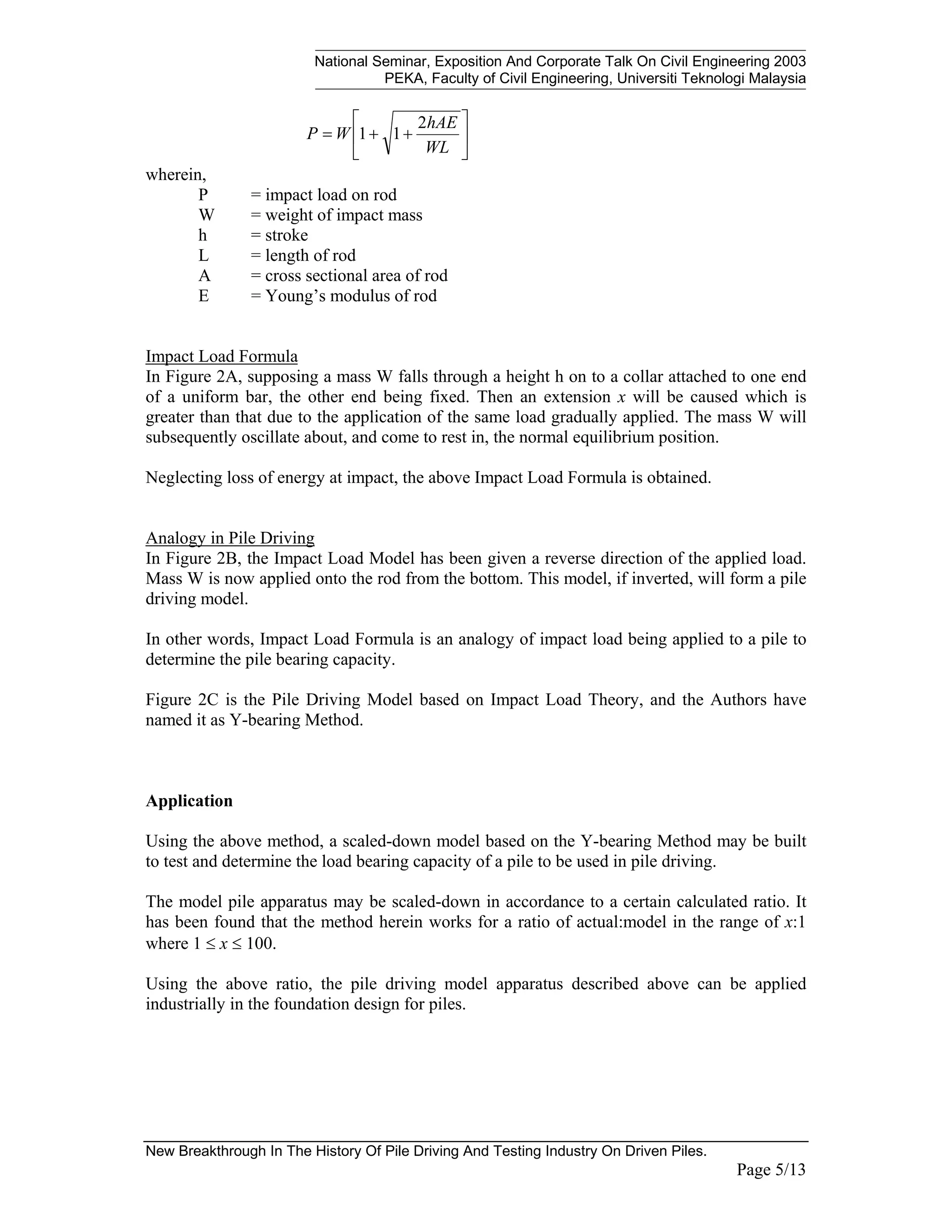
![National Seminar, Exposition And Corporate Talk On Civil Engineering 2003
PEKA, Faculty of Civil Engineering, Universiti Teknologi Malaysia
New Breakthrough In The History Of Pile Driving And Testing Industry On Driven Piles.
Page 6/13
Example: Industry Application
Known properties of Grade J355 Steel:
Pile Modulus, E = 2100 T/cm2
Specific Weight, N = 7.85 T/m3
Yield Strength, y = 355 MPa
Allowable Driving Stress, σall = 213 MPa
Actual Pile:-
Hammer Type: 7-tonnes single acting hydraulic hammer @ ram stroke of 1.2m
with efficiency of 75%
Pile Type: 711mm diameter x 12mm wall thick steel pipe pile with length
of 25m
p
WL
hAE
W
Rp
+
+
=
2
1
1 p: pile
Rp = 7*{1+[1+(2*(1.2*0.75)*263.52*2100)/(7*25)]1/2
} use h multiply efficiency
Rp = 535.17 T
Model Pile:-
m
WL
hAE
W
Rm
+
+
=
2
1
1 m: model
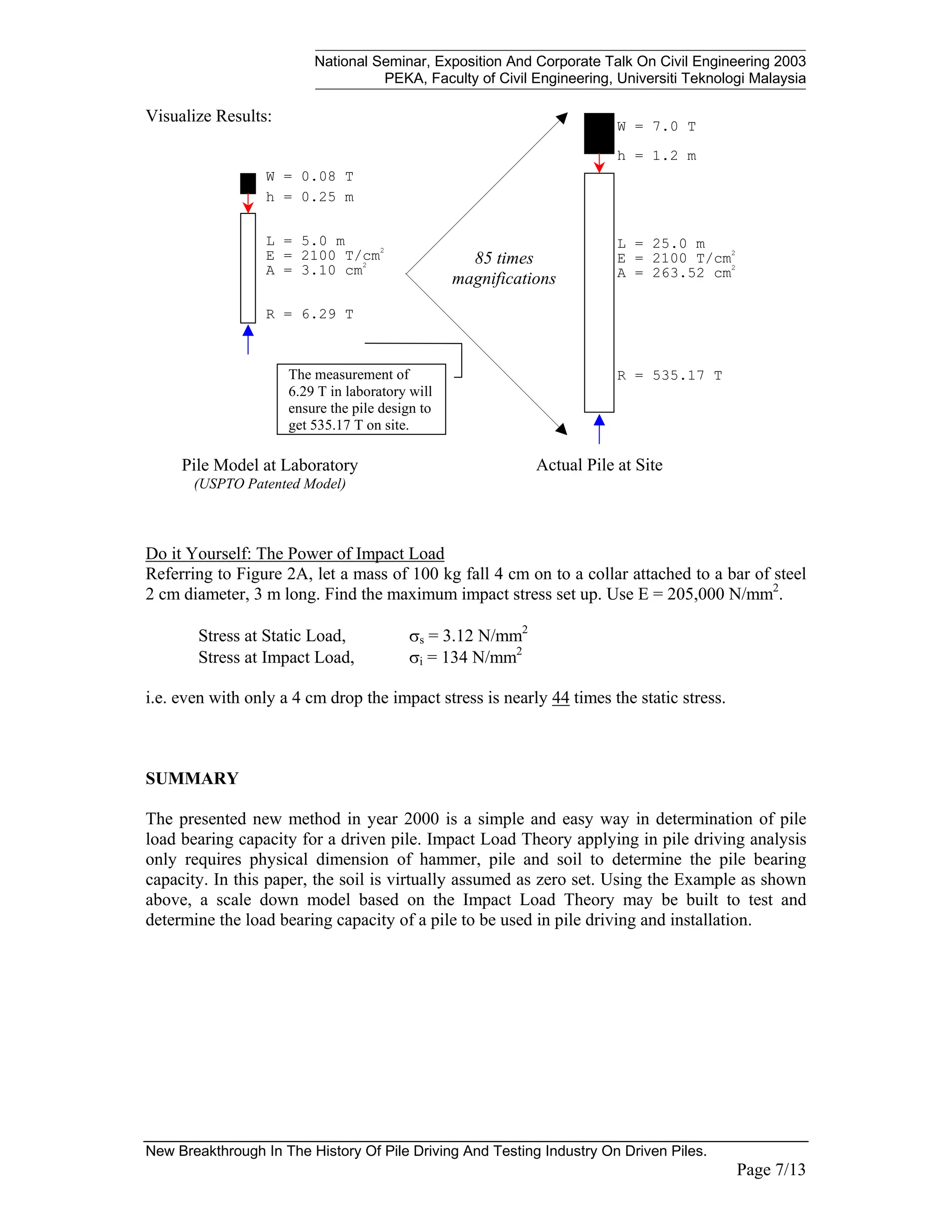
Select a model with the dimensions,
W = 0.08 T = 80 kg
L = 5.00 m
E = 2100 T/cm2
N = 7.85 T/m3
A = 3.10 cm2
Maintaining the same driving stress for the actual and model piles,
Pile Stress, σ = Rm / Am = Rp / Ap
= 535.17 / 263.52
= 203 MPa < σall = 213 MPa (OK!)
=> Obtain Rm = 203 * 3.10
= 6.29 T
Based on this, the ratio of actual:model is,
actual : model
=> Rp : Rm
=> 535.17 : 6.29
=> 85 : 1
What is the drop height required if the above model is used?
Calculated, h = 0.247 m
≈ 0.25 m](https://image.slidesharecdn.com/yjack-2003-impactloadtheorytechpaper2003-piletalk2003newbreakthroughintesting-240709081025-b1c550cf/75/YJACK-Impact-Load-Theory-Tech-Paper-2003-PileTalk-2003-New-Breakthrough-in-Testing-pdf-6-2048.jpg)
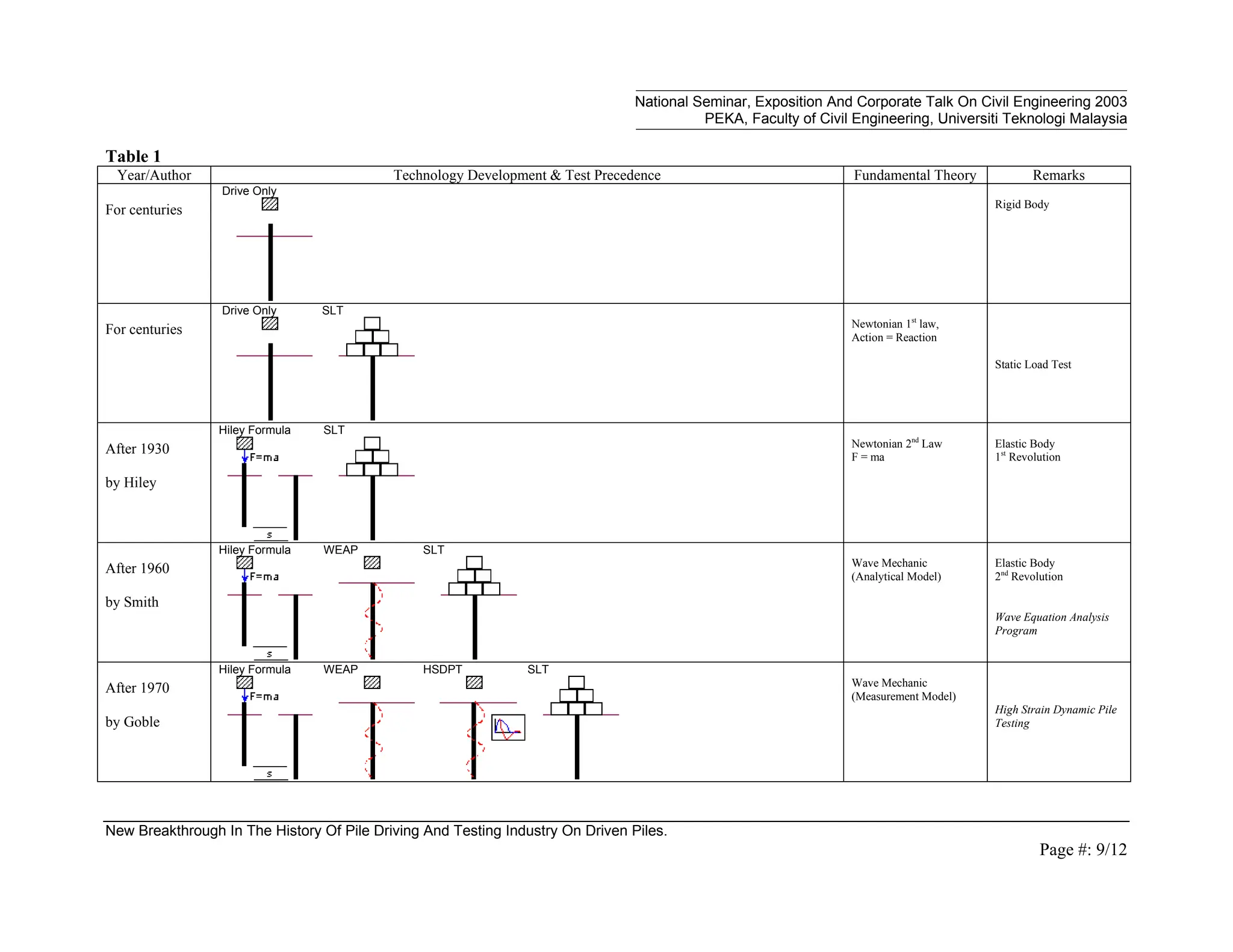

This document presents advancements in pile driving and testing technology, focusing on a new method for determining pile bearing capacities based on impact load theory. It details four major developments in the field, transitioning from treating piles as rigid bodies to utilizing advanced theories like wave mechanics and impact load. The proposed method allows for accurate pile capacity assessments in controlled indoor environments, enhancing the efficiency of foundation design.


