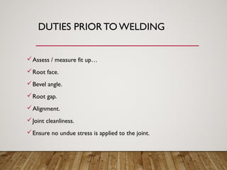
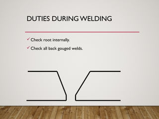
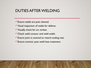
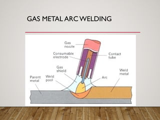
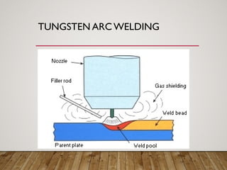
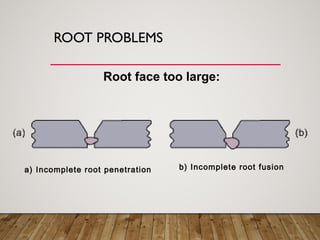
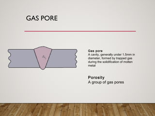
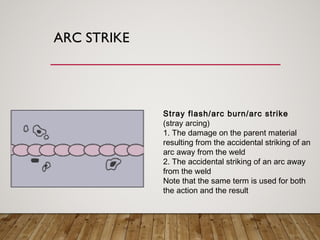
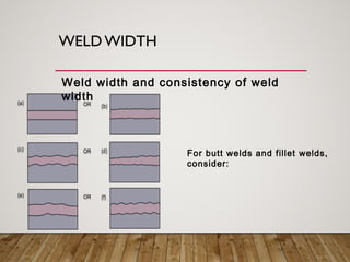
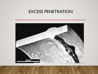
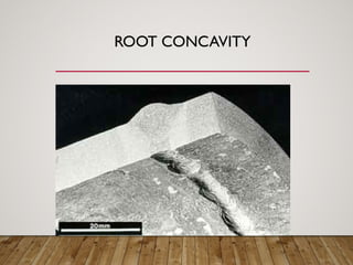
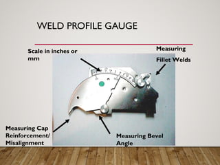
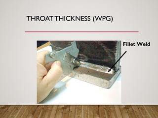
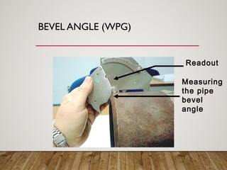
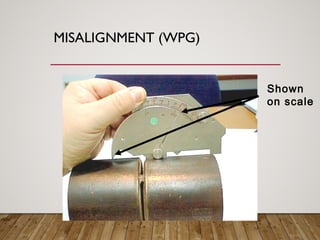
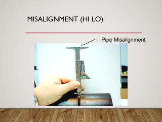
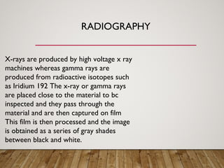
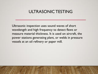
location and identification for defect, grinding then welding build up according to repair procedure ,then flushing .
*step by step fabrication and NDE activities.
How to write a Welding Procedure Specification (ISO 15614-1Tiago Pereira
Some key aspects of writing welding procedure specifications. A good learning point for people who have no experience in the field, and a good reference for seasoned engineers
The Certified Welding Inspector (CWI) plays an important role during any welded construction activities ensuring the required specifications and standards are followed. Due to the numerous materials and processes associated with metal joining (welding) THIS PRESENTATION SHALL SHOW ONLY THE BASIC WELDING PROCESSES AND EXAMINATION METHODS (NDE). National and International Codes and Specifications along with measuring devices are the Inspector’s tools. Hopefully the following presentation shall give an insight into basic welding inspection.
Describe type of welding joint design and welding symbols that usually used in welding design
After completing this chapter, the student should be able to
understand the basics of joint design.
list the five major types of joints.
list seven types of weld grooves.
identify the major parts of a welding symbol.
explain the parts of a groove preparation.
describe how nondestructive test symbols are used.
Each joint’s design affects the quality and cost of the completed weld.
Selecting the most appropriate joint design for a welding job requires special attention and skill.
Welding symbols are the language used to let the welder know exactly what welding is needed.
The welding symbol is used as shorthand and can provide the welder with all of the required information to make the correct weld.
Welding Procedure Specification and Welder approval based on
AWS D.1.1: Structural Steel Welding Code
ASME IX: Welding and Brazing Qualifications
API 1104: Welding of Pipelines
Die casting process: Principles, applications and industrial useMayurjyotiNeog
The short presentation gives insights to some die casting process, its principles, applications and some industrial use. It also includes different die casting methods.
There are numerous welding processes including arc welding, electron beam welding,
friction welding, laser welding, and resistance welding. This article will concentrate on arc
welding, which is the most common technique used to join most steels. Factors affecting
weld quality will be discussed and how to avoid common weld defects will be presented.
Arc welding requires striking a low-voltage, high-current arc between an electrode and the
base metal. The intense heat generated with this arc melts the base metal and allows the
joining of two components. The characteristic of the metal that is being welded and the joint
type (i.e. groove, fillet, etc.) dictates the welding parameters and the procedure that needs to
be followed to obtain a sound weld joint.
A concise presentation about underwater welding. It briefly discusses about the main types, risks involved and practices involved in underwater welding
Welded connections in steel structures - Limit State Design of Steel StructuresAshishVivekSukh
Two members are connected by means of welds is known as welded connection.
More efficient use of the materials.
Earlier designers considered welds as less fatigue resistant.
Good welds achive at site is impossible.
Testing and quality control of welds became easier because NDT
Water scarcity is the lack of fresh water resources to meet the standard water demand. There are two type of water scarcity. One is physical. The other is economic water scarcity.
Student information management system project report ii.pdfKamal Acharya
Our project explains about the student management. This project mainly explains the various actions related to student details. This project shows some ease in adding, editing and deleting the student details. It also provides a less time consuming process for viewing, adding, editing and deleting the marks of the students.
Quality defects in TMT Bars, Possible causes and Potential Solutions.PrashantGoswami42
Maintaining high-quality standards in the production of TMT bars is crucial for ensuring structural integrity in construction. Addressing common defects through careful monitoring, standardized processes, and advanced technology can significantly improve the quality of TMT bars. Continuous training and adherence to quality control measures will also play a pivotal role in minimizing these defects.
Industrial Training at Shahjalal Fertilizer Company Limited (SFCL)MdTanvirMahtab2
This presentation is about the working procedure of Shahjalal Fertilizer Company Limited (SFCL). A Govt. owned Company of Bangladesh Chemical Industries Corporation under Ministry of Industries.
COLLEGE BUS MANAGEMENT SYSTEM PROJECT REPORT.pdfKamal Acharya
The College Bus Management system is completely developed by Visual Basic .NET Version. The application is connect with most secured database language MS SQL Server. The application is develop by using best combination of front-end and back-end languages. The application is totally design like flat user interface. This flat user interface is more attractive user interface in 2017. The application is gives more important to the system functionality. The application is to manage the student’s details, driver’s details, bus details, bus route details, bus fees details and more. The application has only one unit for admin. The admin can manage the entire application. The admin can login into the application by using username and password of the admin. The application is develop for big and small colleges. It is more user friendly for non-computer person. Even they can easily learn how to manage the application within hours. The application is more secure by the admin. The system will give an effective output for the VB.Net and SQL Server given as input to the system. The compiled java program given as input to the system, after scanning the program will generate different reports. The application generates the report for users. The admin can view and download the report of the data. The application deliver the excel format reports. Because, excel formatted reports is very easy to understand the income and expense of the college bus. This application is mainly develop for windows operating system users. In 2017, 73% of people enterprises are using windows operating system. So the application will easily install for all the windows operating system users. The application-developed size is very low. The application consumes very low space in disk. Therefore, the user can allocate very minimum local disk space for this application.
Cosmetic shop management system project report.pdfKamal Acharya
Buying new cosmetic products is difficult. It can even be scary for those who have sensitive skin and are prone to skin trouble. The information needed to alleviate this problem is on the back of each product, but it's thought to interpret those ingredient lists unless you have a background in chemistry.
Instead of buying and hoping for the best, we can use data science to help us predict which products may be good fits for us. It includes various function programs to do the above mentioned tasks.
Data file handling has been effectively used in the program.
The automated cosmetic shop management system should deal with the automation of general workflow and administration process of the shop. The main processes of the system focus on customer's request where the system is able to search the most appropriate products and deliver it to the customers. It should help the employees to quickly identify the list of cosmetic product that have reached the minimum quantity and also keep a track of expired date for each cosmetic product. It should help the employees to find the rack number in which the product is placed.It is also Faster and more efficient way.
Welcome to WIPAC Monthly the magazine brought to you by the LinkedIn Group Water Industry Process Automation & Control.
In this month's edition, along with this month's industry news to celebrate the 13 years since the group was created we have articles including
A case study of the used of Advanced Process Control at the Wastewater Treatment works at Lleida in Spain
A look back on an article on smart wastewater networks in order to see how the industry has measured up in the interim around the adoption of Digital Transformation in the Water Industry.
2. WELDING PRESENTATION
BY
RANDALL STREMMEL
The Certified Welding Inspector (CWI) plays an important role during any welded
construction activities ensuring the required specifications and standards are
followed. Due to the numerous materials and processes associated with metal
joining (welding) THIS PRESENTATION SHALL SHOW ONLY THE
BASIC WELDING PROCESSES AND EXAMINATION METHODS
(NDE). National and International Codes and Specifications along with measuring
devices are the Inspector’s tools. Hopefully the following presentation shall give an
insight into basic welding inspection.
4. WELD FAILURES
Today welding is the most common method used for joining steel
fabrications largely because of the speed at which joints can be made
and the reliability of these joints in service. However because most
welding operations are now relatively simple to perform it is all too
easy to forget the complexity of the chemical and metallurgical actions
that are taking place when the weld is being deposited. Therefore not
surprisingly welds occasionally fail.
5. OVERLOAD
Before applying the various design formulas, the problem itself must
be analyzed and clearly stated. This is not always obvious, and trying
to solve the wrong problem can quickly lead to insufficient design
stresses. When a load is placed on a member, stress and strain
result. Stress is the internal resistance to the applied force. Strain is
the amount of "give or deformation caused by the stress, such as
deflection in bending, elongation in tension, contraction in
compression, and angular twist in torsion.
6. OVERLOAD
For example of this is a lifting lug on a pressure vessel. If the vessel is lifted by
a spreader beam the loading condition on the lug consists of a simple vertical
force putting the attachment welds either in tension or shear. However if the
vessel is lifted with a rope sling the loading condition becomes more complex
because there is now a horizontal component of the force to consider as well
a the vertical one, which effectively increases the loading on the welds.
7. JOINT DESIGN
A welded joint should be designed such that the welder can easily manipulate the electrode to ensure good fusion, particularly in the root of the joint. The profile of each run should be
roughly as wide as it is deep; wide shallow weld beads and particularly deep narrow beads are both ideal candidates for hot cracking.
9. HOT CRACKING
This type of cracking occurs when the weld is starting to solidify,
in the pasty state, as it posses very little strength and therefore
any residual loading is likely to cause it to break before it has fully
solidified. The problem can be compounded by impurities that are
forced out of the solidifying weld, becoming trapped in the center
of the weld during final solidification. Hot cracking can occur
where their is a high degree of restraint in the structure of the
fabrication or where the structure moves slightly as the weld
solidifies.
10. HOT CRACKING
A good example of this type of failure is on the weld used to secure the small
plug in the mandrill hole of a spun dished head on a pressure vessel, a weld that
many people do not take seriously because of its size. As the weld cools it
contracts causing the plug to move , if the weld at the other side of the plug is
still solidifying it could easily fail. This is because of the very high contraction
stresses generated by the plug as the weld starts to solidify.
11. BAD WELDING METHODS
It is very important when carrying out any welding to ensure that it is
done correctly. Consideration has to be given to all aspects of the
process and also the environment. Often welding has to be carried
out under site conditions, the welding is often carried out in situation
so that small general purpose electrodes are used resulting in low
weld heat input which when combined with no preheat gives very
rapid heat dissipation. Which can create a hard micro structure
particularly in the location of the heat affected zone.
12. BAD WELDING METHODS
This along with high levels of residual stress will create the ideal condition for hydrogen induced cracking, which although normally associated with high strength steels
can occur in low carbon steels if the conditions are right. The resulting crack may not occur immediately the weld cools down but some time afterward, therefore if
this type of failure is expected non destructive examination should be delayed by at least 48 hours after welding.
14. METALLURGICAL FAILURE
Materials that are to be welded have to tolerate severe thermal
transients created by the welding process without suffering
deterioration of their mechanical properties or adverse phase
changes. The metallurgical composition or temper conditions of
certain types of metal may make them unsuitable to weld or may
require special controls to be imposed during the welding operation.
For example some steels that are easy to machine may contain high
levels of sulphur that may result in cracking of any attaching weld.
Therefore this type of material should not be used on load bearing
fabricated items such as the eye bolts that are often found holding
down man way covers on pressure vessels.
15. WELD DEFECTS
They can usually be attributed to the welders inability to set up and
manipulate the welding equipment; although bad joint design and
faulty welding equipment can also be responsible. The most
significant defects are cracks and those that resemble cracks such as
lack of fusion, cold overlap etc. This is because of the risk that the
crack may become unstable and propagate when loaded causing a
dramatic failure often by brittle fracture
16. WELD DEFECTS
Porosity seldom causes weld failure in multi-run welds however it
is a sign that something has gone wrong with welding operation
and can often be caused by other defects that may not have been
detected such as lack of side wall fusion. Weld profile can also
cause failure, if the weld size is too small because the joint is
underfilled with weld then its load carrying capability will be
reduced, if the joint contains excessive weld metal this can create a
notch effect which can lead to failure by fatigue if the loading
condition fluctuates.
17. WELD DEFECTS
Bad fit up excessive root penetration on single sided welds can
create defects in the root of the weld such as wormholes and
even cracking. Distortion of welded joints can cause failure by
buckling if the welded member is subjected to compressive loads.
18. CONCLUSION
To minimize these problems the following points should be
considered
•Design of the weld based on the loading condition(s) the join will carry
•Accessibility to enable ease of welding
•Control of distortion
•Careful consideration of the welding environment
•Marching welding process with materials
•A factor of safety applied to the design stress of the weld which should be based
on the consequences of weld failure and the level of NDT that is to be carried out.
20. DUTIES PRIOR TO WELDING
Obtain all relevant documentation…
Relevant specifications.
Relevant procedures.
Copies of welders test test certificates.
Copies of drawings.
21. DUTIES PRIOR TO WELDING
Obtain all relevant documentation…
Ensure welder qualification.
Correct material type condition etc.
Correct equipment with certificates.
Correct consumables type condition, size.
Correct pre heat.
22. DUTIES PRIOR TO WELDING
Assess / measure fit up…
Root face.
Bevel angle.
Root gap.
Alignment.
Joint cleanliness.
Ensure no undue stress is applied to the joint.
25. DUTIES AFTER WELDING
Ensure welds are post cleaned.
Visual inspection of welds for defects.
Visually check for arc strikes.
Check weld contour and weld width.
Ensure joint is covered to retard cooling rate.
Ensure monitor post weld heat treatment.
43. SHAPE (BUTT WELDS)
Ideally, (a) is the most desirable but
very often it may be difficult to achieve.
Because of this, one should assess
the excess weld height in conjunction
with the weld profile and perhaps the
toe blending.
Consider:
44. SHAPE (FILLET WELDS)
In normal practice, (a) is the most desirable
but, again, in many instances it is difficult to
achieve. Acceptance levels, therefore, allow
tolerances on weld shape.
Consider:
45. TOE BLEND (BUTT WELDS)
For butt welds, consider:
In normal practice, (a) is the most
desirable but, again, in many instances
it is difficult to achieve. Acceptance
levels, therefore, allow tolerances on
weld shape.
Depending on the service conditions
of the product, the toe blend may be
of greater importance than the size
and shape of the weld. A poor toe
blend may reduce service life by a
considerable margin if the product is
under a cyclic load.
46. TOE BLEND (FILLET WELDS)
For fillet welds,
consider:
In normal practice, (a) is the most
desirable but, again, in many
instances it is difficult to achieve.
Acceptance levels, therefore,
allow tolerances on weld shape.
47. ROOT DEFECTS
Incomplete root penetration
Failure of weld metal to extend into the root of a joint
Lack of root fusion
Lack of union at the root of a joint
Excess penetration bead
Excess weld metal protruding through the root of
a fusion weld made from one side only
48. ROOT DEFECTS
Root concavity
(suck-back; underwashing - non-standard terms)
A shallow groove which may occur in the root of a
butt weld, but full fusion is evident
Shrinkage groove
A shallow groove caused by contraction in the metal
along each side of a penetration bead or along the
weld centerline
Burn through
(melt through)
A localized collapse of the molten pool due to
excessive penetration, resulting in a hole in the weld
run
49. CONTOUR DEFECTS
Incompletely filled groove
A continuous or intermittent channel in
the surface of a weld, running along its
length, due to insufficient weld metal.
The channel may be along the centre
or along one or both edges of the weld
51. UNEQUAL LEGS
Unequal legs
(non standard term)
Variation of leg length on a fillet weld
Note: Unequal leg lengths may be
specified as part of the design - in which
case they are not imperfections
52. UNDERCUT
Undercut
An irregular groove at a toe of a run in the
parent metal or in previously deposited
weld metal
The inspector must determine if the
undercut is continuous or intermittent, or
sharp or smooth
53. OVERLAP
Overlap
An imperfection at the toe or root of a weld
caused by metal flowing on to the surface of
the parent metal without fusing to it
54. GAS PORE
Gas pore
A cavity, generally under 1.5mm in
diameter, formed by trapped gas
during the solidification of molten
metal
Porosity
A group of gas pores
55. CRATER PIPE
Crater pipe
A depression due to shrinkage at the end of a
run where the source of heat was removed.
Crater pipes may also lead to micro-cracking
56. SURFACE CRACKS
Crack
A linear discontinuity produced by fracture
Cracks may be ...
a) Longitudinal, in the weld metal, i.e. centreline
b) Longitudinal, in the parent metal or heat affected zone
c) Transverse
d) Crater crack (star cracking)
57. ARC STRIKE
Stray flash/arc burn/arc strike
(stray arcing)
1. The damage on the parent material
resulting from the accidental striking of an
arc away from the weld
2. The accidental striking of an arc away
from the weld
Note that the same term is used for both
the action and the result
58. WELD WIDTH
For butt welds and fillet welds,
consider:
Weld width and consistency of weld
width
85. VISUAL INSPECTION
Visual inspection is the one NDT method used extensively to
evaluate the condition or the quality of a weld or component. It is
easily carried out, inexpensive and Visual inspection is the one NDT
method used extensively to evaluate the condition or the quality of
a weld or component. It is easily carried out, inexpensive and
usually doesn't require special equipment.
86. RADIOGRAPHY
X-rays are produced by high voltage x ray
machines whereas gamma rays are
produced from radioactive isotopes such
as Iridium 192 The x-ray or gamma rays
are placed close to the material to bc
inspected and they pass through the
material and are then captured on film
This film is then processed and the image
is obtained as a series of gray shades
between black and white.
87. MAGNETIC PARTICLE INSPECTION
Magnetic particle inspection is a method that can
be used to find surface and near surface flaws in
ferromagnetic materials such as steel and iron.
The technique uses the principle that magnetic
lines of force {flux) will be distorted by the
presence of a flaw in a manner that will reveal it's
presence. the flaw (for example, a crack) is
located from the "flux leakage", following the
application of fine iron particles, to the area under
examination. There are variations in the way the
magnetic field is applied. but they are all
dependant on the above principle .
88. PENETRANT TESTING INSPECTION
Liquid penetration inspection is a method that is used to
reveal surface breaking flaws by bleed out of a colored or
fluorescent dye from the flaw.
89. ULTRASONIC TESTING
Ultrasonic inspection uses sound waves of short
wavelength and high frequency to detect flaws or
measure material thickness. It is used on aircraft, the
power stations generating plant, or welds in pressure
vessels at an oil refinery or paper mill.