SlideShare a Scribd company logo
1 of 52
Gearless Pulling and Lifting Machines
In erection and maintenance, gearless pulling and lifting machines are also very popular. In India
they are commonly known as Hook Chuck or Cumalong. They are called gearless as they don’t
use gears like chain pulley blocks for lifting and pulling application. Information about their
specification and application is given in this article.
In India they are made as per IS 5604: 1984 – Specification for Hand-operated Universal
Gearless Pulling and Lifting Machines (First Revision).
This standard specifies the materials, requirements and testing for the hand-operated gearless
pulling and lifting machines of lifting capacities up to 5 tonnes.
Applications
They are used for various applications like erection of steel structures, laying and pulling of
pipes, guying, tensioning transmission line conductors (electric power transmission), pulling of
under ground cables, moving and installing machines, etc.
Though they are supplied with standard length of wire ropes, there is no restriction on length of
wire rope that can be used in such machines.
It may be noted that lifting and pulling capacity of each machine is different. Some of the
technical data of such machines made by Tractel Tirfor India Pvt. Ltd. are as under.
Technical Data T7 T13 TU20 T35
Lifting Capacity (SWL), Tonnes 0.75 1.6 2.0 3.2
Pulling Capacity, Tonnes 1.25 2.6 3.0 5.2
Effort (Approx.), Kg. 30 to 45 50 47 60
Breaking Load of Rope (Approx.),
Tonnes
4.5 9.0 9.0 16.0
Chain Pulley Blocks
In erection and maintenance, chain pulley blocks are the most commonly used lifting devices.
Information about specifications, operation and inspection of chain pulley blocks is given in this
article.
Specifications
ANSI/ASME B30.16-2007 Overhead Hoists (Underhung)
ASME B30.16 applies to the construction, installation, operation, inspection, testing, and
maintenance of hand chain-operated chain hoists and electric and air-powered chain and wire
ropes hoists used for, but not limited to, vertical lifting and lowering of freely suspended,
unguided, loads which consist of equipment and materials.
Indian Standard
In India, chain pulley blocks are made as per IS 3832: 2005 (Hand-Operated Chain Pulley
Blocks – Specification). This standard lays down the general requirements and testing of the
hand-operated chain pulley blocks, worm or spur gear type. They are tested at 50% overload as
specified in the standard.
They are generally provided with alloy steel load chain as per IS 6216: 1982. This standard
prescribes the requirements for lifting chains, Grade T (8), accurately calibrated for use as load
chains in pulley blocks and other lifting appliances. These are electrically welded round steel
short link chains, fully heat-treated and tested and comply with the general conditions of
acceptance of IS 5616: 1982.
Design safety factor shall be 4.0 or more.
Specifications for a chain pulley block include following items.
• Lifting Capacity (Safe Working Load).
• Number of falls of load chain.
• Effort on hand chain to raise safe working load.
• Weight of Chain pulley block assembly for 3.0 meter lift.
• Extra weight for each additional meter lift.
Effort on hand chain to raise safe working load by one reputed Indian manufacturer for various
capacity of chain pulley blocks is as under.
Lifting Capacity in Kg. 500 1000 2000 3000 5000 8000 10000
Effort on Hand Chain in
Kg.
20 36 38 36 45 52 48
Light chain pulley blocks and chain blocks requiring less pull on hand chain may be selected for
easy of operation.
Operation and Inspection
Check and verify that structure or other equipment (e.g. travelling trolley) that will support the
chain pulley block has a rated load capacity equal to or greater than the rated load capacity of the
chain pulley block to be used.
Operation
• Check that chain is properly seated in sheaves and that chain is not twisted, kinked, or
damaged.
• Don’t wrap chain around load or use chain as a sling.
• Don’t leave load suspended when chain block is unattended unless specific precautions
have been instituted and are in place.
Inspection
Inspect break mechanism, load chain and hook as under.
Break Mechanism
Break is of self actuated screw and disc type. Brakes require more than audible-visual inspection.
Check frequently by stopping chain block with / without load at various positions to test holding
power and amount of drift. If drift is noticed, adjust break.
Periodically check evidence of worn, glazed, or oil-contaminated friction discs; worn pawls,
cams or ratchet; corroded, stretched, or broken pawl springs.
Load Chain
Inspect contact points for excessive wear.
One manufacturer has suggested to measure inside length of 5 links under light tension using a
caliper-type gauge. They have recommended replacing the chain if measurement exceeds
maximum allowable gauge length as given below.
Chain Wire Diameter in
mm
Normal Length of 5 Links in
mm
Maximum Length of 5 Links in
mm
5.0 75 77.6
6.3 95 98.3
7.1 105 108.6
8.0 120 124.1
9.0 135 139.6
Hooks
Hook requires replacement because of excessive bends, twists, or throat opening indicating abuse
or overloading.
Check for cracks (dye penetrant, magnetic particle, or other suitable detection method). Remove
the crack if superficial by grinding. Replace the hook if it is deep.
Hook must be replaced when throat opening measurement has increased 5% over the original
throat opening dimension of a new hook.
A bend or twist of the hook exceeding 10 degrees from the plane of the unbent hook requires
replacement.
Measure hooks depth at load bearing point (base, bowl or saddle). Hook must be replaced when
wear at load bearing point is 10% of the original depth of the hook load bearing point.
Caution:
Never repair hooks by welding or reshaping. Heat applied to the hook will alter the original heat
treatment of the hook material and reduce the strength of the hook.
Rigging Hardware – Wire Rope Clips
Wire rope clips serve as an alternative to splicing and are a simple mechanical means of securing
a wire rope round a thimble. They are also known as Bulldog Clips or wire rope clamps.
Information about specification and method of installing wire rope clips is given in this article.
Wire rope clips are made from two types of materials. They are malleable iron and drop forged
steel. Malleable wire rope clips are to be used only for non-critical, light duty applications with
small applied loads. They should not be used for lifting or suspending load.
Specifications
Wire rope clips are made as per Federal Specification FF-C-450D and ASME B30.26.
As per Federal Specification, they are classified as under.
Type I: Single grip, single saddle, with U-bolts and nuts. They are made in two classes.
Class 1 – Steel saddle.
Class 2 – Malleable iron saddle.
Type II: Double grip, double saddle, with U-bolt and nuts.
Type III: Double grip, double saddle, with bolt and nuts. They are made in two classes.
Class 1: Assembled with integral L-shaped bolts and nuts.
Class 2: Assembled with separate hex head bolts and nuts.
Type IV: Double grip, two taper threaded half clamps with hexagon nut.
Type I and Type III clips are widely used in the industry.
Type III clips having double saddle design eliminates the possibility of incorrect installation.
For dimensional detail, please refer the specification or Crosby’s General Catalog.
For elevator, personnel hoist, and scaffold applications, refer ANSI A17.1 and ANSI A10.4.
These standards do not recommend U-Bolt style wire rope clip terminations.
For OSHA (Construction) applications, see OSHA 1926.251.
Tables showing minimum number of clips to be installed, amount of wire rope required to turn
back and tightening torque for various sizes of forged wire rope clips meeting performance
requirements of Federal Specification FF-C-450D, Type I, Class 1 and Type III are given below.
Type I, Class 1 Clips
Clip Size (in.) Rope Size(mm) Minimum No. of
Clips
Amount of Rope to
Turn Back in mm
*Torque in Nm.
1/8 3-4 2 85 6.1
3/16 5 2 95 10.2
1/4 6-7 2 120 20.3
5/16 8 2 133 40.7
3/8 9-10 2 165 61.0
7/16 11-12 2 178 88
1/2 13 3 292 88
9/16 14-15 3 305 129
5/8 16 3 305 129
3/4 18-20 4 460 176
7/8 22 4 480 305
1 24-25 5 660 305
1-1/8 28-30 6 860 305
1-1/4 33-34 7 1120 488
1-3/8 36 7 1120 488
1-1/2 38-40 8 1370 488
1-5/8 41-42 8 1470 583
1-3/4 44-46 8 1550 800
2 48-52 8 1800 1017
2-1/4 56-58 8 1850 1017
2-1/2 62-65 9 2130 1017
2-3/4 68-72 10 2540 1017
3 75-78 10 2690 1627
3-1/2 85-90 12 3780 1627
Type III Clips
Clip Size (in.) Rope Size(mm) Minimum No. of
Clips
Amount of Rope to
Turn Back in mm
*Torque in Nm.
3/16 5 2 100 40.7
1/4 6-7 2 100 40.7
5/16 8 2 127 40.7
3/8 9-10 2 133 61.0
7/16 11-12 2 165 88.1
1/2 13 3 279 88.1
9/16 14-15 3 323 176
5/8 16 3 342 176
3/4 18-20 3 406 305
7/8 22 4 660 305
1 24-25 5 940 305
1-1/8 28-30 5 1040 488
1-1/4 32-34 6 1400 488
1-3/8 36 6 1570 678
1-1/2 38-40 7 1980 678
*The tightening torque values shown are based upon the threads being clean, dry, and free of
lubrication.
Note: Above tables are reproduces from Crosby’s General Catalog.
Method of Installing Wire Rope Clips
When using wire rope clips, extreme care must be exercised to make certain that they are
attached correctly. Failure to do so could result in serious injury or death. Carry out their
installation as under.
Match the same size wire rope clip to the same size rope diameter. For example, use a 3/8” wire
rope clip with a 3/8” wire rope. Inspect wire rope clip nuts before and after each use.
Wire rope clips should be placed on the wire rope connection with the corrugation in their
saddles coinciding with the lay of the wire rope. Generally saddles are provided with right-hand
helix. For wire rope with left-hand helix, use clips having left-hand helix.
Making an Eye with a Thimble
Turn back specified length of wire rope from thimble (please refer tables given above). Put first
clip one saddle width from seized “dead end” (Figure 1). Seat “live end” (load carrying part) of
wire rope in saddle and position U-bolt over “dead end.” Tighten nuts evenly to proper torque.
Put the second clip as near the loop or thimble as possible (Figure 2). Install nuts firmly but do
not yet tighten to proper torque.
Install all remaining clips equally spaced between the first two clips (Figure 3). Install nuts
firmly but do not yet tighten to proper torque.
Apply light tension to wire rope assembly to take up rope slack and then tighten all nuts evenly
to proper torque.
Add at least one more clip if a pulley (sheave) is used in place of a thimble. If more clips are
used than specified, proportionally increase the amount of wire rope that is turned back.
If Seale construction or similar large outer wire type construction in the 6 x 19 Class is to be
used for sizes 1 inch and larger, add one additional clip.
After assembly, first apply load to test the assembly. This load should be of equal or greater
weight than loads expected in use. Next, check and retighten nuts to recommended torque.
When the required minimum number of clips are installed and nuts are tightened to required
torque, the assembly will develop up to 80% efficiency for clip sizes 1/8" through 7/8" and 90 %
for sizes 1" through 3-1/2"
If more number of clips are used than shown in the table, the amount of turnback should be
increased proportionately.
Wire Rope Splicing (joining) Procedures
The preferred method of splicing two wire ropes together is to use inter-locking turnback eyes
with thimbles, using the recommended number of clips on each eye as shown above.
An alternate method (without using thimbles) is to use twice the number of clips as used for a
turnback termination as shown below. In this method the rope ends are placed parallel to each
other, overlapping by twice the turnback amount. The minimum number of clips should be
installed on each dead end. All other instructions given above shall be followed.
In accordance with good rigging and maintenance practices, the wire rope end termination
should be inspected periodically for wear, abuse, and general adequacy.
Rigging Hardware – Turnbuckles
Information about specification and application for turnbuckles is given in this article.
Specification
Turnbuckles are made as per Federal Specification FF-T-791b, ASME B30.26 and ASTM F-
1145.
Federal Specification FF-T-791b covers swaged, welded, cast or forged turnbuckles with and
without jam nuts. Three types and four form of turnbuckles are made as per this specification as
under.
Type I – Open turnbuckle bodies
Form:
1 – Forged
2 – Spread
3 – Resistance welded and
4 – Arc or gas welded.
Type II – Pipe turnbuckle bodies and
Type III -Rigging turnbuckle bodies.
They are made in eight classes as under.
1 – Turnbuckle, body only without end pulls, heads not drilled.
2 – Turnbuckle, body only without end pulls, heads threaded right and left hand.
3 – Turnbuckle with stub and stub end pulls, complete.
4 – Turnbuckle with eye and eye end pulls, complete.
5 – Turnbuckle with hook and hook end pulls, complete.
6 – Turnbuckle with hook and eye end pulls, complete.
7 – Turnbuckle with jaw and jaw end pulls, complete.
8 – Turnbuckle with jaw and eye end pulls, complete.
Class 4 to Class 8 turnbuckles of Type I, Form 1 (Forged) are shown below.
Turnbuckles and end pulls are made from steel of a grade which will meet recommended
working load limits specified by the specification.
They are made with design factor of 5:1 and recommended working load limits in Pounds for
nominal outside diameter of threads in inch are as under.
Size (inch) Type I, Form 1 All Others
Jaw, eye or stub
end pulls
Hook end pulls Jaw, eye or stub
end pulls
Hook end pulls
¼ 500 300 310 210
5/16 700 500 540 330
3/8 1040 700 820 460
½ 1800 1040 1500 740
5/8 2700 1600 2400 1080
¾ 4000 2000 3600 1500
7/8 5800 2400 5000 2000
1 7600 2900 6600 2560
1 ¼ 12000 4600 10700 4120
1 3/8 14400 5800 12600 4860
1 ½ 17000 7200 15500 5860
1 ¾ 23000 - 21000 -
2 30000 - 27600 -
2 ¼ 39400 - 36200 -
2 ½ 48400 - 44600 -
2 ¾ 60800 - 55400 -
3 70000 - 67400 -
3 ¼ 80000 - 80000 -
3 ½ 95000 - 95000 -
3 ¾ 110000 - 110000 -
4 127000 - 127000 -
Note:
As steel is selected by manufacturer, turnbuckles offered by some manufacturers have higher
safe working load than specified by above specification.
Turnbuckles bodies and ends are available in standard lengths. For dimensional detail, please
refer the specification or Crosby’s General Catalog.
Application
Turnbuckles are recommended for straight or in-line pull only.
Generally open forged turnbuckles are used for hoisting and rigging operations.
If a turnbuckle is used in an application where vibration is present, the end fittings should be
secured to the frame with lock pins or wires to prevent them from turning and loosening.
Lock nuts are available for all sizes of turnbuckles.
Rigging Hardware – Hooks and Swivels
Information about material, specification, marking and application for hooks and swivels is given
in this article.
Hooks
Hooks are installed on cranes, hoists, etc. and are also used for rigging. Rigging hooks are used
as part of rigging tackle, such as sling assemblies, or with below-the- hook lifting devices. They
are available in carbon steel and alloy steel materials. They are made as per requirements of
ASME B30.10 and Federal specification RR-C-271D.
A latch, or mousing, bridges the throat opening of the hook for the purpose of retaining slings,
chains, or similar parts under slack conditions and is not intended to support the load. Latch
equipped hooks shall be used for all hoisting and rigging operations unless the application makes
use of the latch impractical, or unsafe.
Many styles of hooks are available. Two typical rigging hooks are shown below.
Some rigging hooks (e.g., sorting hooks) are designed to carry the load near the point/tip as well
as in the bowl or saddle of the hook. The designated SWL applies only when the load is applied
in the bowl or saddle of the hook. Generally forged alloy steel hooks are used as rigging hooks.
The manufacturer’s identification shall be forged or die-stamped on the hook.
Application
Load shall be applied in the bowl or saddle of the hook.
Side loading, back loading and tip loading as shown below are conditions that damage and
reduce the capacity of the hook.
Inspection
All hooks shall be inspected as per statutory requirements.
Service Classification for Hooks
Hooks fitted on cranes, hoists, etc. are classified based on service/use as under.
Normal Service: Service that involves operating at less than 85% of rated load except for
isolated instances.
Heavy Service: Service that involves operating at 85% to 100% of rated load as a regular
specified procedure.
Severe Service: Heavy service coupled with abnormal operating condition.
Hooks fitted on cranes, hoists, etc. having any of the following conditions shall be discarded.
• Deformation: Any bending or twisting visible to the inspector.
• Throat Opening: Any distortion causing an increase in throat opening exceeding 5% or
as otherwise directed by the hook manufacturer.
• Wear: Any wear exceeding 10% of the original section dimension of the hook or its load
pin or as otherwise directed by the hook manufacturer.
• Cracks: Any visible crack.
• Latch engagement: Damaged or malfunctioning latch (if provided).
• Nondestructive Testing: Hooks with a rated load greater than or equal to 10 tons and
assigned to heavy or severe service shall receive an NDT by a qualified inspector.
Rigging hooks shall be visually inspected for the following deficiencies before use:
• Distortions such as bending, or twisting exceeding 10 degrees from the plane of the
unbent hook.
• Increased throat opening exceeding 15%.
• Wear exceeding 10% of the original dimension.
• Cracks, severe nicks, or gouges.
• Hook attachment and securing means.
Rigging hooks shall be inspected as a part of the slings to which they are attached. The NDT of
rigging hooks is not routinely required.
NDT Methods
Magnetic particle testing or liquid penetrant testing methods shall be utilized to inspect for
surface intersecting discontinuities (i.e., stress or fatigue cracks).
NDT shall be done in accordance with the following American Society of Testing and Materials
(ASTM) standards:
ASTM E-709, Standard Practice for Magnetic Particle Examination.
ASTM E-165, Standard Practice for Liquid Penetrant Inspection Method.
For magnetic particle testing, a coil, yoke, or wet technique should be used to eliminate the
possibility of prod burns or arc strikes.
Repair of Hooks
Hooks with a crack, nick, or gouge shall be repaired by grinding lengthwise, following the
contour of the hook, provided that the reduction of dimension is within the permissible limits as
shown below.
ZONE A: Repair not required
ZONE B: 10% of original dimension
ZONE C: 5% of original dimension
ZONE D: Follow minimum thread size chart
Hooks shall not be repaired, altered, reworked, or reshaped by welding, heating, burning, or
bending.
QUIC-CHECK® Feature
For quickly checking of hooks for deformation, Crosby provides Deformation Indicators and
distance between them – AA as shown below for hoist hooks. Two markings are forged into the
product, one just below the shank or eye and the other on the hook tip. This allows for
measurement to determine if the throat opening has changed, thus indicating abuse or overload.
It is called QUIC-CHECK® Feature by Crosby.
If there is no marking on a hook, two punch marks may be made on a hook and distance between
them recorded. Measurement of distance between them after use will show deformation if any.
Barrel Hooks
They are used to handle barrels/drums. They are made from forged carbon steel. They are made
as per Federal Specification RR-C-271D, Type V, Class 6.
Hooks made by Crosby has Working Load Limit of 1000 Kg (per pair of hooks) and has
following dimensions.
I D of Eye = 39.6 mm.
O D of Eye = 71.4 mm
Overall Length = 174 mm and
Width of Lip = 73.2 mm.
Swivels
Swivels are positioning devices and are not intended to rotate under load. They are made as per
Federal Specification RR-C-271D, Type VII. Swivels together with their pins shall be forged
from carbon steel. They are made in three classes as shown below.
Class 1: Chain Swivel
Class 2: Eye and Eye Swivel and
Class 3: Jaw and Eye Swivel.
Rigging Hardware – Eye Bolts
Information about eye bolt’s material, specification, marking and application is given in this
article.
Material, Specification and Marking
Eye bolts are made from forged carbon steel or alloy steel. Alloy steel eye bolts are forged,
quenched, and tempered with improved toughness properties, intended primarily for low-
temperature applications. Carbon steel eye bolts (ASTM A489) shall have the manufacturer’s
name or identification mark forged in raised characters on the surface of the eye bolt. Alloy steel
eye bolts (ASTM F541) shall have the symbol “A” (denoting alloy steel) and the manufacturer’s
name or identification mark forged in raised characters on the surface of the eye bolt.
Eye bolts are made as per ANSI/ASME B18.15 and ASME B30.26.
ASME B18.15 is limited to dimensions and capacities for forged threaded eye bolts intended
primarily for lifting applications, and cover the following types and styles:
Type 1, Plain Pattern (straight shank); Style A – Long Length; Style B – Short Length.
Type 2, Shoulder Pattern; Style A – Long Length; Style B – Short Length.
Short Length Shoulder Pattern eye bolts are also known as Machinery Type eye bolts.
ASME B30.26 include identification, ductility, design factor, proof load and temperature
requirements.
Eye bolts shall have a minimum design factor of 5, based on ultimate strength. Working Load
Limit shown is for in-line pull.
Eye bolts manufactured in accordance with ASTM A489 (Standard Specifications for Carbon
Steel Lifting Eyes) are rated for lifting service between +30°F and +275°F. These temperature
limitations are also referenced in ASME B18.15 (Forged Eye bolts). Eye bolts manufactured in
accordance with ASTM F 541 (Alloy Steel Eye bolts) are rated for use at a low temperature of
-40°F. ASTM F 541 requires the symbol “A” to denote alloy steel.
Safe Working Load for Carbon Steel Shouldered Eye bolts as per ANSI/ASME B18.15 is as
under.
Norminal
size (in.)
Inside
diameter of
eye (in.)
Safe Working Load for Shouldered Eye bolt (lb)
Vertical 30° from
vertical
60° from vertical 90° from vertical
1/4 0.69 400 75 Not recommended Not
recommended
3/8 0.94 1,000 400 220 180
1/2 1.12 1,840 850 520 440
5/8 1.31 2,940 1,410 890 740
3/4 1.44 4,430 2,230 1,310 1,140
1 1.69 7,880 3,850 2,630 2,320
1 1/4 2.12 12,600 6,200 4,125 3,690
1 1/2 2.44 18,260 9,010 6,040 5,460
2 3.06 32,500 15,970 10,910 9,740
Safe Working Load for Carbon Steel Eye bolts as per ASME B30.26 for vertical (in-line) loading
for Inch and Metric sizes are as under.
Size (in.) Working Load Limit (lbs.)
1/4 650
5/16 1,200
3/8 1,550
1/2 2,600
5/8 5,200
3/4 7,200
7/8 10,600
1 13,300
1-1/4 21,000
1-1/2 24,000
Metric Size Working Load Limit – kg
m6 200
m8 400
m10 640
m12 1000
m16 1800
m20 2500
m24 4000
m30 6000
m36 8500
For angular lifts, adjust working load as follows:
Direction of Pull Adjusted Working Load
45 degrees 30% of rated working load
90 degrees 25% of rated working load
IS 4190: 1984
Indian standard for eye bolts is IS 4190: 1984 (Specification for Eye Bolts with Collars). This
standard specifies the basic dimensions, material, lifting capacity and conditions of use of lifting
eyebolts of Grade M. These eyebolts, which are described as `universal` may be used in all cases
involving vertical and inclined lifting. This standard covers only eyebolts with eyes of internal
diameters capable of permitting direct engagement with eyehooks of the same lifting capacity
(working load limit) for use with Grade T(8) chain. In the case of eyehooks for use with Grade
M(4) chain, it may be necessary to use an intermediate component such as a shackle to make the
connection.
Application
It is recommended to use shouldered eye bolts for rigging hardware, except when prohibited by
the configuration of the item to which the eye bolt is attached. Where non-shouldered eye bolts
are required, they shall be used only in vertical pulls or in rigging systems that are designed,
analyzed, and approved by a qualified person.
For vertical loading, eye bolts without shoulders have the same load-carrying ability as
shouldered eye bolts.
Shoulders of eye bolts shall seat uniformly and snugly against the surface on which they bear.
Never undercut eye bolt to seat shoulder against the load. Always countersink receiving hole or
use washers to seat shoulder.
When more than one eye bolt is used in conjunction with multiple-leg rigging, spreader bars or
lifting beams should be used to eliminate angular loading. In case two or more than two eye bolts
are used without spreader bars, their orientation shall be such that load is in the plane of the eyes
as shown below (Orientation of eye bolts). When eye bolts cannot be properly seated and aligned
with each other, a steel washer or spacer not to exceed one thread pitch may be required to put
below the eye bolt. Proper thread engagement must be maintained. Use a washer with
approximately the same diameter as the eye bolt shoulder and the smallest inside diameter that
will fit the eye bolt shank.
If the hook does not go completely into the eye bolt, use a shackle to avoid loading the hook tip.
Installation for In-line Loading
For in-line loading application use regular nut eye bolt or shoulder nut eye bolt. Use number of
nuts based on thickness of load as shown below.
Use one nut if thickness is more than one eye bolt diameter. Use two nuts if thickness is less than
or equal to eye bolt diameter. Always tighten nuts securely against the load.
Installation for Angular Loading
Use shoulder nut eye bolt for angular loading. If the eye bolt protrudes so far through the load
that the nut cannot be tightened securely against the load, use properly sized washers to take up
the excess space between the nut and the load as shown below. Thickness of washers / spacer
must exceed the distance between the bottom of the load and the last thread of the eye bolt.
Reeving of Sling
Slings shall not be reeved through an eye bolt or reeved through a pair of eye bolts. Reeving will
alter the angle of loading on the eye bolt as shown below. Only one leg should be attached to
each eye bolt.
Machinery Eye Bolt – Installation for In-line & Angular Loading
These eye bolts are primarily intended to be installed into tapped holes. For installation, tap the
load (tap depth) to a minimum depth of one-half the eye bolt size beyond the shank length of the
machinery eye bolt. If the plane of the machinery eye bolt is not aligned with the sling line, add
shims (washers) of proper thickness to adjust the angle of the plane of the eye to match the sling
line as shown below.
To attain the rated capacity, minimum thread shank length of engagement depends on parent
material and must be as follows:
Steel: 1 thread diameter
Cast iron, brass, bronze: 1.5 times the thread diameter
Aluminum, magnesium, zinc, plastic: 2 times the thread diameter
Swivel Hoist Ring
Swivel hoist ring shown above is a patented product manufactured by The Crosbygroup Inc. and
is available in UNC and Metric thread sizes. One of the main advantages for its use is self
alignment of its eye with the load angle due to swivel movement and they are rated 100% for 90
degree angle. It gives 360° swivel and 180° pivot action as shown below.
Eye Bolt Inspection
Visually inspect each eye bolt before use. Eye bolts that are worn, cracked, bent, elongated or
have damaged threads shall be discarded. Ensure that threads on shank and receiving hole are
clean.
Note:
For more information on eye bolts (dimensions) and swivel hoist rings (different type of rings)
please refer General Catalog of the Crosby Group.
Acknowledgement:
Sketches in this article are based on sketches in General Catalogue by Crosby Group.
Rigging Hardware – Shackles
In rigging various types of hardware are used to hold loads. Information about shackle’s
specification and application is given in this article.
Specifications
Shackles are manufactured in two configurations – Anchor Shackle and Chain Shackle. They are
also known as Bow Shackle and Dee Shackle. Both are available with screw pin, round pin, or
bolt type as shown below.
In USA, shackle specifications are defined by the following documents, depending on the
shackle size:
For shackles 3/16 to 2 3/4 inches, the specifications are derived from Federal Specification RR-
C-271, “Chains and Attachments, Welded and Weldless.”
For shackles 1 1/2 to 4 inches, the specifications are derived from MIL-S-24214, “Shackles,
Steel, General Purpose and High Strength.”
For shackles 4 1/2 to 8 1/2 inches, ASTM A148M, “Standard Specification for Steel Castings,
High Strength, For Structural Purposes,” should be used.
Note:
For the overlaps in size, with RR-C-271 and MIL-S-24214, either specification may be used;
however, RR-C-271 is most commonly used. Catalogs and manufacturers’ literature will list the
federal specification number as “RR-C-271(rev.).”
Two grades of shackles are made as per specification RR-C-271D.
Grade A shackles, together with their pins and bolts are forged from carbon steel. Grade B
shackles together with their pins and bolts are forged from alloy steel.
Recommended safe working loads for these grades are as under.
Recommended Safe Working Load (Maximum) in Pounds
Size (D) inches Grade A Grade B Size (D) inches Grade A Grade B
3/16 520 900 1-1/4 16,500 36,000
1/4 710 2,000 1-3/8 19,800 41,400
5/16 1,060 3,120 1-1/2 23,740 48, 800
3/8 1,590 3,800 1-5/8 27,900 57,400
7/16 2,170 5,180 1-3/4 32,320 65,000
1/2 2,830 6,500 2 42,220 85,040
9/16 3,580 - 2-1/4 54,000 -
5/8 4,420 10,000 2-1/2 67,600 121,400
3/4 6,360 13,800 2-3/4 81,000 -
7/8 8,650 18,700 3 96,200 150,000
1 11,310 24,400 3-1/2 131,100 200,000
1-1/8 13,360 28,600 4 171,140 260,000
It may be noted that shackles are sized by the diameter of steel in the bow section rather than the
pin size. The recommended safe working loads are for In-Line loading. In In-Line loading, load
is applied perpendicular to pin. If load is to be applied at an angle, it must be applied in the plane
of the bow as shown below.
For side loading screw pin and bolt type shackles, safe working load shall be reduced as per
following table.
Angle of Side Load from Vertical (In-Line of
Shackle)
Adjusted Working Load Limit
0°, In-Line 100% of Rated Working Load Limit
45° from In-Line 70% of Rated Working Load Limit
90° from In-Line 50% of Rated Working Load Limit
However, shackles symmetrically loaded with two leg slings having a maximum included angle
of 120° as shown below can be utilized to full Working Load Limit.
Design Factors:
Shackles manufactured in accordance with RR-C-271 and MIL-S-24214 have a minimum design
factor of 5. Shackles manufactured to the requirements of ASTM A148M have a minimum
design factor of 4.
Shackles for critical-lift service shall have an initial proof load test of two times the SWL
(minimum). Before making a critical lift, ensure that the shackle has been proof tested.
ASME specification number for shackles is B30.26.
Specification number IS 6132: 2003, Forged Shackles for General Lifting Purposes – Dee
Shackles and Bow Shackles is applicable in India. This Indian Standard is identical with ISO
2415: 1987 `Forged shackles for general lifting purposes – Dee shackles and bow shackles'
issued by the International Organization for Standardization (ISO).
ISO 2415:2004 specifies the general characteristics of forged dee and bow shackles in a range of
sizes having working load limits of from 0,32 t to 100 t and in Grades 4, 6 and 8, and presents
their performance and critical dimensions necessary for their interchangeability and
compatibility with other components.
Shackles by Crosby
In addition to normal shackles, Crosby makes two special types of shackles as under.
Wide Body Shackle
Use of wide body shackles increases sling bearing surface and eliminates need for a thimble. Due
to higher D/d ratio, it also increases usable sling strength.
COLD TUFF® shackles
They are suitable for use to -50° F.
Application
Select type of a shackle as under.
Round Pin Shackles: They can be used in tie down, towing, suspension or lifting applications
where the load is strictly applied in-line.
Screw Pin Shackles: They can be used in any application where a round pin shackle is used. In
addition, screw pin shackles can be used for applications involving side-loading circumstances.
Reduced working load limits are required for side-loading applications. While in service, do not
allow the screw pin to be rotated by a live line, such as a choker application.
Bolt-Type Shackles: They can be used in any applications where round pin or screw pin
shackles are used. In addition, they are recommended for permanent or long term installations
and where the load may slide on the shackle pin causing the pin to rotate.
Useful Information on Use of a Shackle
The shackle pin shall never be replaced with a bolt; only a properly fitted pin shall be used. Bolts
are not intended to take the load that is normally applied to the pin as shown below.
Centralize whatever is being hoisted on the pin by suitable washers or spacers as shown below.
Screw pin shackles shall not be used if the pin can roll under load and unscrew as shown below.
When using a shackle to make choker hitch, place pin in the eye of sling as shown below.
Slings
Slings are the most commonly used piece of materials handling apparatus. They are used with
material handling equipments like cranes, chain pulley blocks, etc. to hold suspended loads.
Based on type of construction, there are mainly three types of slings. They are single leg sling,
multiple leg sling (for bridal hitch with two, three or four legs) and end less sling (grommet
type). Numerous sling end configurations and fittings/attachments are available for various
applications.
There are six types of slings based on material of manufacture – wire rope slings, alloy steel
chain slings, synthetic web slings, synthetic round slings, metal mesh slings and fibre rope slings.
Information about these slings is given in this article.
Wire Rope Slings
Wire rope slings are a basic material handling tool and are the most frequently used type of
slings in industry. Wire rope slings are made from wire ropes with either Independent Wire Rope
Core (IWRC) or a fiber core. A sling manufactured with a fiber core is usually more flexible but
is less resistant to environmental damage. Sling made of an independent wire rope core has
greater strength and is more resistant to heat damage. Mostly slings are made from wire rope
having right hand regular lay of 6×19 or 6×37 construction. Wire rope slings are made from
various grades of wire rope, but the most common grades in use are Improved Plow Steel, Extra
Improved Plow Steel (EIPS) and Extra Extra Improved Plow Steel (EEIPS).
Construction
Slings ends are generally made with plain loops or with thimbles.
Sling with Plain Loops
Sling with plain loops at both ends is used for general purpose lifting. The sling eye shall have
maximum angle of 15 º a shown above. Generally the eye dimensions are W = 8d and L = 16d
where d = wire rope diameter.
Sling with Thimbles
Thimble (shown above) is the reinforcing member of a rope eye. It protects the rope at the point
of attachment. Thimbles are fitted to sling ends to protect the rope against wear and abrasion
from hooks, links, pins, etc. Heavy duty thimbles are used for protection against concentrated
wear. Commonly used sling end configurations with thimbles are shown below.
Sometime spelter or swaged type sockets are fitted at the end of a wire rope as shown below.
Sling ends are made by hand splicing, mechanical splicing or by rope clips as under.
Hand Splicing
Hand splice is made by forming an eye and "tucking" and "locking" a strand of the wire rope
under other adjacent strands (interweaving the wire rope strands). Splicing by this method
requires skill, is time consuming and requires long rope. The method is now replaced by
mechanical splicing.
Mechanical Splicing
In mechanical splicing, the end of wire rope after forming an eye is secured to the sling body
(wire rope) by pressing a metal sleeve/ferrule. A hydraulic swaging press with special dies is
used to bond the sleeve in place. Extreme pressure forces the sleeve material to flow into the
voids between the wires and strands, creating an assembly that maintains most of the wire rope's
nominal breaking strength. This type of eye is known as loop back eye.
Flemish Eye
In Flemish Eye, the rope firstly undergoes a limited form of hand spliceing (Flemish Splicing)
which is then completed by mechanically swaging a steel sleeve/ferrule over the ends of the rope
as shown below.
Flemish eye is fabricated by unlaying the rope body into two parts, one having three strands, the
other having the remaining three strands and core. The rope is unlayed far enough back to allow
the eye to be formed by looping one part in one direction and the other part in the opposite
direction and laying the rope back together. The strands are rolled back around the rope body and
a metal sleeve is slipped over the ends and pressed (swaged) to secure the ends to the sling body.
Rope Clips/Clamps
It is recommended not to use wire rope clips (shown above) to fabricate wire rope slings, except
where the application precludes the use of prefabricated slings and where the sling is designed
for the specific application by a qualified person. It is also advised not to use slings made with
wire rope clips in a choker hitch. If sling ends are fabricated by wire rope clips, they shall be
made of drop forged steel and using adequate number of clips at recommended spacing. U bolt
of a clip shall be fitted over the dead end of the rope and the live rope shall rest in the clip saddle.
The clips shall be evenly tightened to recommended torque before and after the initial load is
applied and shall be inspected regularly to ensure that the recommended torque remains.
Slings fabricated using wire rope clips shall be de-rated to 80% of the rated wire rope load
capacity to account for the efficiency of the clips.
Swage Fittings and Spelter Sockets
Above picture shows open and closed type of swage and spelter sockets.
In case of swage fitting, a wire rope end is inserted into the fitting bore and swaged onto the rope
(like mechanical splicing).
In case of a spelter socket, a wire rope end is inserted in the socket and attached to it by pouring
molten metal (Zinc or White Metal) or resin in the fitting basket (cup).
For more information on spelter socketing procedures, please refer following standards.
IS 3937: Recommendation for socketing of wire ropes (Part 1: with Zinc, Part 2: with White
Metal and Part 3: with resins).
ISO 7595: Socketing procedures for wire ropes―Molten metal socketing.
ISO 7596: Socketing procedures for wire ropes―Resin sockting.
For more information on splicing, please refer IS 5245 as under.
IS 5245, Part 1: Methods for splicing of wire ropes, Part 1 – Hand splicing of wire ropes.
IS 5245, Part II: Methods for splicing of wire ropes, Part II – Wire rope sling legs with Ferrule-
Secured eye terminals.
Braided and Cable-Laid Slings
Braided Sling
8-part braided slings are fabricated from 8 pieces of small diameter wire ropes, braided together
to form one large sling. They can be either flat or round. They are commonly used for high
capacity lifts. They snug tightly to a load in a choker hitch, resist kinking and offer the ultimate
in flexibility.
Cable-Laid Sling
Cable-laid slings are fabricated from a rope comprised of 7 small wire ropes. This construction
creates a very pliable sling and is used where flexibility and resistance to kinking are more
important than resistance to abrasion. Since the rope is made up of many smaller wire ropes, the
sling can bend around smaller diameters without taking a permanent set or kink. The small wires,
however, are susceptible to abrasion.
Minimum Length of a Sling
It is recommended to have minimum length of sling as under.
Slings made of rope with 6×19 and 6×37 classifications and cable slings should have a minimum
clear length of rope 10 times the component rope diameter between splices, sleeves, or end
fittings.
Braided slings should have a minimum clear length of rope 40 times the component rope
diameter between the loops or end fittings.
Grommets and endless slings should have a minimum circumferential length of 96 times the
body diameter of the grommet or endless sling.
Proof Loads
Wire rope sling assemblies shall be proof tested using the following criteria:
Hand Tucked: The proof load for hand-tucked slings shall be a minimum of the rated load and
shall not exceed 1.25 times the rated load.
Wire Rope Clips: The proof load for wire rope clip slings shall be a minimum of the rated load
and shall not exceed two times the rated load.
Others Configurations: The proof load for other types of slings including mechanical splice,
zinc-poured, resin poured, and swaged socket shall be two times the rated load.
Multiple Leg Slings: The proof load for multiple-leg bridle slings shall be applied to the
individual legs. The proof load for the individual legs shall be consistent with the particular
single-leg assembly stated above. Any master link to which multiple legs are connected shall be
proof loaded to two times the force applied by the combined legs.
D/d Ratio
The capacity of a wire rope sling can be greatly affected by being bent sharply around pins,
hooks, or parts of a load. The wire rope industry uses the term “D/d ratio” to express the severity
of bend. “D” is diameter of curvature that the rope or sling is subjected to and “d” is the diameter
of the rope. The minimum D/d ratio is usually taken as 20 which correspond to 92 % efficiency.
Rated Loads / Capacity
Safe Working Load (SWL) Limit / Rated Capacity of a sling depend on strength of material
(wire rope), fabrication efficiency and design factor (factor of safety).
Rated capacities (SWL) of commonly used single leg slings for vertical lifting expressed in Tons
(2000 lb) are as given under. Rated loads in the tables are based on design factor of 5 and
minimum D/d ratio of 25/1.
Wire Rope Classification: 6×19 or 6×37
Type of Core: Fiber Core (FC)
Wire Rope Grade (Tensile Strength): Extra Improved Plow Steel (EIPS) Grade
Rope Diameter
inch
Rated Capacity in Tons (2000 lb)
Hand-tucked splice Mechanical splice Swaged or poured (spelter)
socket
¼ 0.54 0.56 0.60
5
/16 0.83 0.87 0.94
3
/8 1.2 1.2 1.3
7
/16 1.6 1.7 1.8
½ 2.0 2.2 2.4
9
/16 2.5 2.7 3.0
5
/8 3.1 3.4 3.7
¾ 4.3 4.8 5.2
7
/8 5.7 6.6 7.1
1 7.4 8.3 9.2
1 1
/8 9.3 10 12
1 1
/4 11 13 14
Wire Rope Classification: 6×19 or 6×37
Type of Core: Independent Wire Rope Core (IWRC)
Wire Rope Grade (Tensile Strength): Extra Improved Plow Steel (EIPS) Grade
Rope Diameter
inch
Rated Capacity in Tons (2000 lb)
Hand-tucked splice Mechanical splice Swaged or poured (spelter)
socket
¼ 0.54 0.65 0.68
5
/16 0.83 1.0 1.1
3
/8 1.2 1.4 1.5
7
/16 1.6 1.9 2.0
½ 2.0 2.5 2.7
9
/16 2.5 3.2 3.4
5
/8 3.1 3.9 4.1
¾ 4.3 5.6 5.9
7
/8 5.7 7.6 8.0
1 7.4 9.8 10
1 1
/8 9.3 12 13
1 1
/4 11 15 16
1 3
/8 14 18 19
1 ½ 16 21 23
1 5
/8 19 24 26
1 ¾ 22 28 31
1 7
/8 25 32 35
2 28 37 40
Wire Rope Classification: 6×19 or 6×37
Type of Core: Independent Wire Rope Core (IWRC)
Wire Rope Grade (Tensile Strength): Extra Extra Improved Plow Steel (EEIPS) Grade
Rope Diameter
inch
Rated Capacity in Tons (2000 lb)
Hand-tucked splice Mechanical splice Swaged or poured (spelter)
socket
¼ 0.60 0.71 0.74
5
/16 0.92 1.1 1.2
3
/8 1.3 1.6 1.7
7
/16 1.7 2.1 2.2
½ 2.2 2.8 2.9
9
/16 2.8 3.5 3.7
5
/8 3.4 4.3 4.5
¾ 4.7 6.2 6.5
7
/8 6.2 8.3 8.8
1 8.1 11 11
1 1
/8 10 - 14
1 1
/4 13 - 18
1 3
/8 15 - 21
1 ½ 18 - 25
1 5
/8 21 - 29
1 ¾ 24 - 34
1 7
/8 27 - 38
2 31 - 43
Indian sling manufacturers generally offer following two types of mechanically spliced slings in
wire rope construction 6×19 or 6×37.
1. Wire rope with fibre core made from galvanized wire as per Grade 1570 (160 Kgf / mm2
).
2. Wire rope with steel core made from black wire as per Grade 1770 (180 Kgf / mm2
=
Improved Plow Steel).
Rated capacities (SWL) of these single leg slings for vertical lifting expressed in Tonne (1000
Kgf) based on design factor of 5 are as under.
Rope Diameter
mm
Safe Working Load in Tonnes (1 Tonne = 1000 Kgf)
Galvanized wire as per Grade 1570 Black wire as per Grade 1770
6 0.32 -
7 0.43 -
8 0.57 0.81
9 0.72 1.04
10 0.89 1.2
11 1.1 1.5
12 1.3 1.8
13 1.5 2.1
14 1.7 2.5
16 2.3 3.2
18 2.9 4.1
20 3.6 5.1
2 4. 6.2
24 5.1 7.4
26 6.0 8.6
28 7.0 10.0
32 9.1 13.1
36 - 16.6
40 - 20.5
44 - 24.8
48 - 29.5
52 - 34.8
Note:
Generally wire rope of 6×19 classification is used for wire rope diameter up to and including 1
inch. For wire rope diameter larger than 1 inch, 6×37 classification is used.
IS 2762: Specification for wire rope slings and sling legs covers dimensions, construction,
loading, tests and marking of one-, two-, three- and four-leg slings for wire ropes of nominal
diameter 8 to 44 mm, having legs of following types:
a) Single part spliced,
b) Double part spliced endless, and
c) Double part grommet.
To get lighter slings, please specify wire rope with independent wire rope core (IWRC) made
from wires having higher tensile strength (say 220 Kgf /mm2
which is equivalent to grade 2160 /
Extra Extra Improved Plow Steel Grade) and factor of safety = 5.
Construction Safety Association of Ontario recommends to use wire rope slings made from from
improved plow steel with independent wire rope core to reduce the risk of crushing.
Attachments
Various types of attachments like link, hook, swivel hook, plate lifting clamp, etc. are attached to
sling eyes for various applications. When two or more slings are connected to a common link for
make a lifting bridal, the assembly is called multiple leg sling.
Above picture shows two, three and four leg slings with oblong link and eye hooks. Three and
four leg slings are used for level lifting of a load.
When using a multiple leg sling, ensure that the rating shown for the single leg sling is not
exceeded in any leg of the multiple leg sling.
All attachments shall have a rated capacity equal to or greater than that of the wire rope sling.
Ensure that all welded end attachments are tested by the manufacturer or equivalent entity at
twice their rated capacity before initial use.
Effect of Environment
Permanently remove from service fiber core wire rope slings of any grade if they are exposed to
temperatures in excess of 180º F (82º C).
Follow the recommendations of the sling manufacturer when you use metallic core wire rope
slings of any grade at temperatures above 400º F (204º C) or below minus 40º F (minus 40º C).
Inspection and Removal
Make periodic inspections of slings at intervals not greater than 12 months. Do not inspect a
sling by passing bare hands over the wire rope body. Broken wires, if present, may puncture the
hands. Deterioration that would result in loss of original strength shall be observed. Remove
sling from service if any of the following conditions are present:
• Severe localized abrasion or scraping of one-third the original diameter of outside
individual wires.
• Kinking, crushing, bird caging or any other damage resulting in distortion of the rope
structure.
• Evidence of heat damage.
• End attachments that are cracked, deformed, or worn to the extent that the strength of the
sling is substantially affected.
• Severe corrosion of the rope or end attachments.
• For strand-laid and single-part slings, ten randomly distributed broken wires in one rope
lay or five broken wires in one strand in one rope lay.
• Broken wires in braided and cable-laid slings as per table given below.
Sling body Allowable broken wires per lay or
one braid
Allowable broken strands per sling
length
Less than eight-part
braid
20 1
Eight-part braid and 40 1
more
Cable laid 20 1
Recommendations on Use of Wire Rope Slings
Use wire rope slings with independent wire rope core (IWRC) to reduce the risk of crushing.
All eyes be fitted with thimbles and formed by Flemish Splice and secured by swaged or pressed
ferrules/sleeves (mechanical splicing). Flemish Eye has reserve strength in case of failure of
ferrule/sleeve.
Wire rope slings shall not be shortened or lengthened by knotting or twisting or with wire rope
clips or other methods not approved by the sling manufacturer.
Do not subject fiber core wire rope slings to degreasing or to a solvent because of possible
damage to the core.
Wire rope wedge sockets shall not be used to fabricate wire rope slings.
Go to Top
Alloy Steel Chain Slings
Chain slings are used for application requiring flexibility and resistance to abrasion, cutting and
high temperatures.
Construction and Rated Loads
Chain slings used for overhead lifting applications must be manufactured from alloy steel. Alloy
steel chain slings are made from various grades of alloy, but the most common grades in use are
grades 80 and 100. Rated loads for alloy steel chain slings shall be based on a minimum design
factor of 4. If other grades of chain are used, use them in accordance with the manufacturer's
recommendations and guidance. The general configuration of a chain sling is as shown below.
Rated loads (with Design Factor = 4) for vertical lift of single leg alloy steel Grade 80 and Grade
100 chain slings are as shown under.
Nominal Chain Size Rated Load in lb
inch mm Alloy Steel Chain Grade 80 Alloy Steel Chain Grade 100
7/32 5.5 2,100 2,700
9/32 7 3,500 4,300
5/16 8 4,500 5,700
3/8 10 7,100 8,800
1/2 13 12,000 15,000
5/8 16 18,100 22,600
3/4 20 28,300 35,300
7/8 22 34,200 42,700
1 26 47,700 -
1-1/4 32 72,300 -
Note:
As per Construction Safety Association of Ontario, like all other slings and attachments, chain
slings and attachments must have design factor (factor of safety) of 5.
IS 2760: Specification for steel chain slings covers the requirements, methods of rating and
testing of single-, two-, three- and four-leg or branch welded chain slings of Grades L (3), M (4),
S (6) and T (8) using chains conforming to IS 2429 : Part I : 1970, IS 3109 : Part I : 1970, IS
6217 : 1971 and IS 6215 : 1971 respectively together with the appropriate range of components.
Attachments
All attachments shall have a rated capacity at least equal to that of the steel chain with which
they are used.
All welded components in the sling assembly shall be proof-load tested as components or as part
of the sling assembly.
Where used, handles shall be welded to the master link or hook before heat treatment (This
prohibits welding on chain slings during field operations.).
Effect of Temperature
If the chain sling gets heated to a temperature above 400°F (204°C), rated loads shall be reduced
in accordance with the chain manufacturer’s recommendations regarding usage both while
heated and after being heated. If chain slings are to be used in temperatures of -40°F (-40°C) or
less, the manufacturer should be consulted.
Typical reduction of chain sling’s rated load (Safe Working Load) according to temperature is as
under.
Temperature Grade of Chain
Grade 80 Grade 100
(°F) (°C) Temporary
Reduction of Rated
Load WHILE AT
Temperature
Permanent
Reduction of Rated
Load
AFTER
EXPOSURE to
Temperature
Temporary
Reduction of Rated
Load WHILE AT
Temperature
Permanent Reduction
of Rated Load
AFTER EXPOSURE
to
Temperature
Below
400
Below
204
NONE NONE NONE NONE
400 204 10% None 15% None
500 260 15% None 25% 5%
600 316 20% 5% 30% 15%
700 371 30% 10% 40% 20%
800 427 40% 15% 50% 25%
900 482 50% 20% 60% 30%
1000 538 60% 25% 70% 35%
Over
1000
Over
538
REMOVE FROM SERVICE
Inspection, Repairing / Reconditioning and Removal
Make periodic inspections of steel chain slings at intervals no greater than 12 months.
Make a thorough inspection of slings and attachments. Look for wear, defective welds, nicks,
cracks, breaks, gouges, stretch, bends, discoloration due to excessive heat, excessive pitting or
corrosion, throat opening of hooks, etc.
Minimum allowable thickness at any point on a link is as under.
Nominal Chain or Coupling Link
Size
Minimum Allowable Thickness at Any Point on The Link
Inch mm Inch mm
7/32 5.5 0.189 4.80
9/32 7 0.239 6.07
5/16 8 0.273 6.93
3/8 10 0.342 8.69
1/2 13 0.443 11.26
5/8 16 0.546 13.87
3/4 20 0.687 17.45
7/8 22 0.750 19.05
1 26 0.887 22.53
1 1/4 32 1.091 27.71
Note: Minimum allowable chain thickness is approximately 12 % reduction in diameter.
Use damaged slings only after they are repaired / reconditioned and proof tested by the sling
manufacturer or a qualified person. Alloy steel chain, attachments, and coupling links used for
repair shall conform to the strength requirements and other requirements of the original sling. It
is recommended to replace rather than repair cracked, broken, or bent links.
Recommendations on Use of Chain Slings
Slings should be padded to prevent links from being bent and to protect the load.
Chain links and attachments shall hinge freely with adjacent links.
Chain slings shall not be shortened or lengthened by knotting, twisting, or other methods as
shown below.
Go to Top
Synthetic Web Slings
Synthetic web slings are light and flexible. They are fabricated by sewing woven synthetic
webbing of nylon or polyester (Dacron) yarns. They are often selected when expensive, highly
polished, fragile or delicate loads are to be lifted. The softness of the web will not mar, deface or
scratch loads, while its flexibility assures a firm, secure grip around the item being lifted. Web
slings have the ability to elongate, absorbing and minimizing the effects of shock loads. Nylon is
resistant to many alkalis where as polyester is resistant to many acids. Since they are non-
sparking, they can be safely used in explosive atmospheres. Nylon slings are more common but
polyester slings are often recommended where headroom is limited since they stretch only half as
much as nylon slings. Synthetic web slings may be coated with suitable material to improve
abrasion resistance, protection from sunlight or ultraviolet degradation, seal out moisture, and
prevent grit from penetrating the web and causing internal wear.
Construction and Rated Loads
Slings can be fabricated from single or multiple plies, may include accessories such as edge
guard, wear pads or sleeves, and are available in several configurations as under.
Type I
Sling made with a triangle fitting on one end and a slotted triangle choker fitting on the other
end. It can be used in a vertical, basket, or choker hitch.
Type II
Sling made with a triangle fitting on both ends. It can be used in a vertical or basket hitch only.
Type III
Sling made with flat loop eye on each end with loop eye opening on same plane as sling body.
This type of sling is sometimes called a flat eye-and-eye, eye-and-eye, or double-eye sling.
Type IV
Sling made with both loop eyes formed as in Type III, except that the loop eyes are turned to
form a loop eye which is at a right angle to the plane of the sling body. This type of sling is
commonly referred to as a twisted-eye sling.
Type V
Endless sling, sometimes referred to as a grommet. It is a continuous loop formed by joining the
ends of the webbing together.
Type VI
Return-eye (reversed-eye) sling is formed by using multiple widths of webbing held edge-to-
edge. A wear pad is attached on one or both sides of the sling body and on one or both sides of
the loop eyes to form a loop eye at each end which is at a right angle to the plane of the sling
body.
Synthetic web slings are made from two class of stuffer weave construction webbing with a
minimum certified tensile strength per inch of width of the webbing as under.
Class 5 Webbing – 6800 pounds.
Class 7 Webbing – 9800 pounds.
Rated loads for Type I, II, III and IV single leg slings for vertical lift for various constructions
are as under.
Width
inch
Rated Load in Pounds
One-ply
Class 5
Webbing
Two-ply
Class 5
Webbing
One-ply
Class 7
Webbing
Two-ply
Class 7
Webbing
Four-ply
Class 7
Webbing
1 1,100 2,200 1,600 3,100 5,500
1 1/2 1,600 3,300 2,300 4,700 -
1 3/4 1,900 3,800 2,700 5,400 -
2 2,200 4,400 3,100 6,200 11,000
3 3,300 6,600 4,700 8,800 16,450
4 4,400 8,200 6,200 11,000 20,400
5 5,500 10,200 7,800 13,700 25,500
6 6,600 12,300 9,300 16,500 30,600
Note: For Type VI slings, consult the manufacturer for rated loads
The rated capacity of synthetic web slings is based on the tensile strength of the webbing, a
factor of safety of 5, and fabrication efficiency. Fabrication efficiency is typically 80 % to 85 %
for single-ply slings but will be lower for multi-ply slings and very wide slings.
For slings made from other type of construction, select them based on rated load shown on sling
identification.
Synthetic webbing materials other than nylon and polyester are also used and the manufacturer
should be consulted for specific data for proper use.
Sling Attachments
If synthetic web slings incorporate metal fittings, the fittings shall have the following properties:
• Materials are compatible with the mechanical and environmental requirements of the
sling.
• Fittings have a rated load at least the same as the synthetic webbing sling.
• They shall have sufficient strength to sustain twice the rated load of the sling without
permanent deformation and a minimum breaking strength equal to five times the rated
capacity of the sling.
• Surfaces shall be cleanly finished and sharp edges removed to prevent damage to the
webbing.
To protect slings against wear and cutting due to repeated use against sharp corners, they are
fitted with protective devices like buffer strips, edge guards and sleeve or sliding tube wear pads.
Effects of Environment
Certain synthetic materials perform better than others in specific applications and environments.
Consult the sling manufacturer or a qualified person for a specific application or before using in
and around chemical environments. High radiation or chemically active environments can
destroy the strength of synthetic web slings. Specific environmental limits are as follows:
Do not use nylon and polyester slings in contact with objects or at temperatures in excess of 194º
F (90º C), or below minus 40º F (minus 40º C).
Synthetic slings made from Kevlar (Kevlar is a registered trademark of DuPont de Nemours.), K-
Spec (K-Spec is a registered trademark of SlingMax.) and nylon may be used in radiation areas
when the responsible person ensures that the absorbed dose do not exceed 100,000 rad during the
life of the sling.
Nylon web slings shall not be used where fumes, vapors, sprays, mists or liquids of acids are
present.
Polyester web slings shall not be used where fumes, vapors, sprays, mists, or liquids of caustics
are present.
Synthetic web slings are not recommended where extensive exposure to sunlight or ultraviolet
light is experienced.
Store slings in an area where they will not be subjected to mechanical, chemical, or ultraviolet
damage, or to extreme temperatures.
Inspection and Removal Criteria
Inspection should be made by the person handling the sling each day the sling is used. Periodic
inspection shall be carried out at least annually by a qualified inspector.
Sling need replacement if cuts, holes, tears, broken stitching, worn eyes and worn or corroded or
distorted fittings, burns from acid, caustics or heat are found.
Caution on Use of Synthetic Web Slings
When using sling in bridle and basket configurations, they should be used with extreme caution.
At low sling angles one edge of the web will be overloaded and the sling will tend to tear as
shown below.
Go to Top
Synthetic Round Slings
Synthetic round slings also offer a number of advantages like synthetic web slings. They offer
one additional advantage in that their jackets shield the fibre against ultraviolet degradation. A
round sling is also easy to inspect and evaluate – if its jacket is damaged, take it out of service.
Round slings have larger capacities than synthetic web slings of the same width. They can
therefore be narrower.
Synthetic round slings are identified by Size Numbers adopted by the Web Sling and Tie Down
Association to describe a slings or by Colour but always select them based on the vertical rated
load shown on the sling identification.
Go to Top
Metal Mesh Slings
Metal mesh slings are widely used in metalworking and in other industries where loads are
abrasive, hot, or will tend to cut web slings. Unlike nylon and wire rope slings, metal mesh slings
resist abrasion and cutting. Metal mesh slings grip the load firmly without extensive stretching.
Construction and Rated Loads
Material for Fabric Construction: Carbon Steel.
Fabric Construction Heavy Duty Medium Duty Light Duty
Nominal spiral turns per foot mesh
width
35 43 59
Approx. spiral wire size 10 gage 12 gage 14 gage
Equivalent decimal size 0.135 in. 0.105 in. 0.080 in.
Nominal cross rods per foot of fabric
length
21 30 38
Approx. size of cross rods 8 gage 10 gage 14 gage
Equivalent decimal size 0.162 in. 0.135 in. 0.080 in.
Nominal fabric thickness 1/2 in. 3/8 in. 5/16 in.
Rated loads of Metal Mesh Slings based on Design Factor = 5 for vertical and choker lift are as
under.
Width inch Rated Loads in Pounds (lbs)
Heavy Duty Medium Duty Light Duty
2 1,600 1,450 900
3 3,000 2,170 1,400
4 4,400 2,900 2,000
6 6,600 4,800 3,000
8 8,800 6,400 4,000
10 11,000 8,000 5,000
12 13,200 9,600 6,000
14 15,400 11,200 7,000
16 17,600 12,800 8,000
18 19,800 13,500 9,000
20 22,000 15,000 10,000
Metal mesh slings are also made from materials other than carbon steel. They are made from
alloy steel for higher rated loads and stainless steel for corrosive environments.
Effect of Environment
Metal mesh slings can be used without a rated load reduction in temperatures ranging from
minus 20º F (minus 29º C) to 550º F (288º C) except elastomer-coated slings. Use elastomer-
coated slings in temperature ranges of 0º F (minus 18º C) to 200º F (93º C).
Inspection
Make periodic inspections of metal mesh slings at intervals not greater than 12 months. Look for
following items.
• Broken wires in any part of the mesh.
• Broken weld or broken brazed joint along the sling edge.
• Reduction in wire diameter of 25 percent or more due to abrasion or 15 percent or more
due to corrosion.
• Lack of flexibility due to distortion of the mesh.
• Pitted, corroded, cracked, bent, twisted, gouged, or broken fittings.
Go to Top
Natural and Synthetic Fibre Rope Slings
Slings manufactured from conventional three-strand natural or synthetic fiber rope are not
recommended for use in lifting service. Natural or synthetic fiber rope slings shall be used only if
other sling types are not suitable for the unique application.
Rated loads for synthetic fibre rope slings based on Design Factor = 5 and vertical lift are as
under.
Rope Diameter
inch
Rated Loads for Vertical Lift in Pounds (lbs)
Nylon Polyester Polypropylene
1/2 1,100 1,000 760
9/16 1,400 1,300 920
5/8 1,800 1,600 1,100
3/4 2,600 2,200 1,500
7/8 3,500 3,000 2,100
1 4,400 4,000 2,600
1 1/8 5,700 5,000 3,200
1 1/4 7,000 6,000 3,900
1 5/16 7,700 6,500 4,200
1 1/2 9,700 8,400 5,500
1 5/8 11,500 9,900 6,400
1 3/4 13,200 11,400 7,400
2 16,900 14,400 9,400
2 1/8 19,100 16,200 10,500
2 1/4 21,400 18,100 11,900
2 1/2 26,300 22,000 14,400
2 5/8 28,800 24,200 16,100
3 37,100 31,200 20,500
D/d ratio for rope slings shall be larger than 8/1.
Go to Top
General Recommendations on Use of Slings
All types of slings shall have, as a minimum, the rated capacity clearly and permanently marked
on each sling.
Each sling shall receive a documented inspection at least annually, more frequently if
recommended by the manufacturer or made necessary by service conditions.
Wire rope slings shall be labeled with a tag or other identification methods similar to one shown
below.
When repaired, a sling shall be permanently marked to identify the repairing agency.
New and repaired / reconditioned slings including welded components shall be proof load tested
by the sling manufacturer or repair agency.
Replace hooks that have been opened more than 15% of the normal throat opening measured at
the narrowest point or twisted more than 10° from the plane of the unbent hook.
Ensure that in a choker hitch, the choke point is only on the sling body, never on a fitting.
Do not rest loads on the sling. Do not pull a sling from under a load when the load is resting on
the sling.
Do not drag slings on the floor or over abrasive surfaces.
For more information on slings please refer ANSI/ASME B30.9.

More Related Content

What's hot

Intro to fastener_technology_part3_r2010
Intro to fastener_technology_part3_r2010Intro to fastener_technology_part3_r2010
Intro to fastener_technology_part3_r2010navair
 
Rigging safety 7
Rigging safety 7Rigging safety 7
Rigging safety 7vtsiri
 
Solid Shank Rivet Codes
Solid Shank Rivet CodesSolid Shank Rivet Codes
Solid Shank Rivet Codesaimeeharden
 
Wringer_roll_Position_control_final(edited)
Wringer_roll_Position_control_final(edited)Wringer_roll_Position_control_final(edited)
Wringer_roll_Position_control_final(edited)SHASHANK KUMAR
 
Types of toggle clamp sp2
Types of toggle clamp sp2Types of toggle clamp sp2
Types of toggle clamp sp2toggleclamp
 
Etc 02-04 - steel sleepers installation procedure
Etc 02-04 - steel sleepers installation procedureEtc 02-04 - steel sleepers installation procedure
Etc 02-04 - steel sleepers installation procedureNECB
 
Tolomatic rsa gsa rod-style screw drive actuator brochure
Tolomatic rsa gsa rod-style screw drive actuator brochureTolomatic rsa gsa rod-style screw drive actuator brochure
Tolomatic rsa gsa rod-style screw drive actuator brochureElectromate
 
Thread Gaging: Accurate Gaging Methods for Higher Quality Threads
Thread Gaging: Accurate Gaging Methods for Higher Quality ThreadsThread Gaging: Accurate Gaging Methods for Higher Quality Threads
Thread Gaging: Accurate Gaging Methods for Higher Quality ThreadsLiberato Pietrantoni
 
Indian standard specification for high strength structural bolts
Indian standard specification for high strength structural boltsIndian standard specification for high strength structural bolts
Indian standard specification for high strength structural boltsJisha John
 
Types of toggle clamp sp2
Types of toggle clamp sp2Types of toggle clamp sp2
Types of toggle clamp sp2toggleclamp
 
Flange Shaft Coupling
Flange Shaft CouplingFlange Shaft Coupling
Flange Shaft CouplingBilal Murtaza
 
Linear guide roller bearing
Linear guide roller bearingLinear guide roller bearing
Linear guide roller bearingVicky Chou
 
Meeka brochure Hoist-2017
Meeka brochure Hoist-2017Meeka brochure Hoist-2017
Meeka brochure Hoist-2017Chitvan Mehta
 
Toyota 02 5 fd45 forklift service repair manual
Toyota 02 5 fd45 forklift service repair manualToyota 02 5 fd45 forklift service repair manual
Toyota 02 5 fd45 forklift service repair manualhfjsekekmmd
 

What's hot (20)

Rigging Safety Training by ATP
Rigging Safety Training by ATPRigging Safety Training by ATP
Rigging Safety Training by ATP
 
Intro to fastener_technology_part3_r2010
Intro to fastener_technology_part3_r2010Intro to fastener_technology_part3_r2010
Intro to fastener_technology_part3_r2010
 
Rigging safety 7
Rigging safety 7Rigging safety 7
Rigging safety 7
 
Fasteners
FastenersFasteners
Fasteners
 
3559
35593559
3559
 
Solid Shank Rivet Codes
Solid Shank Rivet CodesSolid Shank Rivet Codes
Solid Shank Rivet Codes
 
Wringer_roll_Position_control_final(edited)
Wringer_roll_Position_control_final(edited)Wringer_roll_Position_control_final(edited)
Wringer_roll_Position_control_final(edited)
 
Types of toggle clamp sp2
Types of toggle clamp sp2Types of toggle clamp sp2
Types of toggle clamp sp2
 
Etc 02-04 - steel sleepers installation procedure
Etc 02-04 - steel sleepers installation procedureEtc 02-04 - steel sleepers installation procedure
Etc 02-04 - steel sleepers installation procedure
 
Tolomatic rsa gsa rod-style screw drive actuator brochure
Tolomatic rsa gsa rod-style screw drive actuator brochureTolomatic rsa gsa rod-style screw drive actuator brochure
Tolomatic rsa gsa rod-style screw drive actuator brochure
 
The Basics of Thread Rolling
The Basics of Thread RollingThe Basics of Thread Rolling
The Basics of Thread Rolling
 
Thread Gaging: Accurate Gaging Methods for Higher Quality Threads
Thread Gaging: Accurate Gaging Methods for Higher Quality ThreadsThread Gaging: Accurate Gaging Methods for Higher Quality Threads
Thread Gaging: Accurate Gaging Methods for Higher Quality Threads
 
Scaffolding
ScaffoldingScaffolding
Scaffolding
 
Indian standard specification for high strength structural bolts
Indian standard specification for high strength structural boltsIndian standard specification for high strength structural bolts
Indian standard specification for high strength structural bolts
 
Types of toggle clamp sp2
Types of toggle clamp sp2Types of toggle clamp sp2
Types of toggle clamp sp2
 
Flange Shaft Coupling
Flange Shaft CouplingFlange Shaft Coupling
Flange Shaft Coupling
 
Linear guide roller bearing
Linear guide roller bearingLinear guide roller bearing
Linear guide roller bearing
 
785
785785
785
 
Meeka brochure Hoist-2017
Meeka brochure Hoist-2017Meeka brochure Hoist-2017
Meeka brochure Hoist-2017
 
Toyota 02 5 fd45 forklift service repair manual
Toyota 02 5 fd45 forklift service repair manualToyota 02 5 fd45 forklift service repair manual
Toyota 02 5 fd45 forklift service repair manual
 

Similar to Gearless pulling and lifting machines

Selection criteria and design of a chain used for Lifting Application
Selection criteria and design of a chain used for Lifting ApplicationSelection criteria and design of a chain used for Lifting Application
Selection criteria and design of a chain used for Lifting Applicationijsrd.com
 
HSE_TM_06_Material handling Safety.pptx
HSE_TM_06_Material handling Safety.pptxHSE_TM_06_Material handling Safety.pptx
HSE_TM_06_Material handling Safety.pptxjohnraj44
 
Below the hook PPT Training
   Below the hook  PPT  Training    Below the hook  PPT  Training
Below the hook PPT Training Bill Brown
 
bevel gear screw jack,high speed screw jack,quick lifting screw jack,gear rat...
bevel gear screw jack,high speed screw jack,quick lifting screw jack,gear rat...bevel gear screw jack,high speed screw jack,quick lifting screw jack,gear rat...
bevel gear screw jack,high speed screw jack,quick lifting screw jack,gear rat...Jacton Electromechanical Co.,Ltd
 
Safety consideration in Ropes , Slings and Fiber Ropes
Safety consideration in Ropes , Slings and Fiber RopesSafety consideration in Ropes , Slings and Fiber Ropes
Safety consideration in Ropes , Slings and Fiber RopesMANNU KUMAR
 
Jcb js130 t2 excavator service repair manual sn from 2373080 to 2375080
Jcb js130 t2 excavator service repair manual sn from 2373080 to 2375080Jcb js130 t2 excavator service repair manual sn from 2373080 to 2375080
Jcb js130 t2 excavator service repair manual sn from 2373080 to 2375080fhsejkdkmem
 
Jcb js130 t3 excavator service repair manual sn from 2373080 to 2375080
Jcb js130 t3 excavator service repair manual sn from 2373080 to 2375080Jcb js130 t3 excavator service repair manual sn from 2373080 to 2375080
Jcb js130 t3 excavator service repair manual sn from 2373080 to 2375080fhsejkdkmem
 
Jcb js130 t2 excavator service repair manual sn from 2373080 to 2375080
Jcb js130 t2 excavator service repair manual sn from 2373080 to 2375080Jcb js130 t2 excavator service repair manual sn from 2373080 to 2375080
Jcb js130 t2 excavator service repair manual sn from 2373080 to 2375080fjjskekfksme
 
Jcb js115 t2 excavator service repair manual sn 2397465 and up
Jcb js115 t2 excavator service repair manual sn 2397465 and upJcb js115 t2 excavator service repair manual sn 2397465 and up
Jcb js115 t2 excavator service repair manual sn 2397465 and upfudjjjskeskmmd
 
Jcb js130 t3 excavator service repair manual sn from 2373080 to 2375080
Jcb js130 t3 excavator service repair manual sn from 2373080 to 2375080Jcb js130 t3 excavator service repair manual sn from 2373080 to 2375080
Jcb js130 t3 excavator service repair manual sn from 2373080 to 2375080fuseokdmmed
 
Jcb js115 t3 excavator service repair manual sn 2397465 and up
Jcb js115 t3 excavator service repair manual sn 2397465 and upJcb js115 t3 excavator service repair manual sn 2397465 and up
Jcb js115 t3 excavator service repair manual sn 2397465 and upikfkksmem
 
Jcb js130 t3 excavator service repair manual sn from 2373080 to 2375080
Jcb js130 t3 excavator service repair manual sn from 2373080 to 2375080Jcb js130 t3 excavator service repair manual sn from 2373080 to 2375080
Jcb js130 t3 excavator service repair manual sn from 2373080 to 2375080fusjejfskekem
 
Jcb js145 excavator service repair manual sn 2397465 and up
Jcb js145 excavator service repair manual sn 2397465 and upJcb js145 excavator service repair manual sn 2397465 and up
Jcb js145 excavator service repair manual sn 2397465 and upcdfvvv
 
Jcb js130 excavator service repair manual sn from 2373080 to 2375080
Jcb js130 excavator service repair manual sn from 2373080 to 2375080Jcb js130 excavator service repair manual sn from 2373080 to 2375080
Jcb js130 excavator service repair manual sn from 2373080 to 2375080fujsefkxswksemm
 
Jcb js130 t2 excavator service repair manual sn from 2373080 to 2375080
Jcb js130 t2 excavator service repair manual sn from 2373080 to 2375080Jcb js130 t2 excavator service repair manual sn from 2373080 to 2375080
Jcb js130 t2 excavator service repair manual sn from 2373080 to 2375080jfjkskrtekfmsmem
 
Jcb js130 t2 excavator service repair manual sn 2397429 and up
Jcb js130 t2 excavator service repair manual sn 2397429 and upJcb js130 t2 excavator service repair manual sn 2397429 and up
Jcb js130 t2 excavator service repair manual sn 2397429 and upfujsefkxswksemm
 
Jcb js115 t2 excavator service repair manual sn 2397465 and up
Jcb js115 t2 excavator service repair manual sn 2397465 and upJcb js115 t2 excavator service repair manual sn 2397465 and up
Jcb js115 t2 excavator service repair manual sn 2397465 and upfjjskekdmmme
 
Jcb js115 t3 excavator service repair manual sn 2397465 and up
Jcb js115 t3 excavator service repair manual sn 2397465 and upJcb js115 t3 excavator service repair manual sn 2397465 and up
Jcb js115 t3 excavator service repair manual sn 2397465 and upfujsefkksemm
 

Similar to Gearless pulling and lifting machines (20)

Selection criteria and design of a chain used for Lifting Application
Selection criteria and design of a chain used for Lifting ApplicationSelection criteria and design of a chain used for Lifting Application
Selection criteria and design of a chain used for Lifting Application
 
Below the hook
Below the hook Below the hook
Below the hook
 
HSE_TM_06_Material handling Safety.pptx
HSE_TM_06_Material handling Safety.pptxHSE_TM_06_Material handling Safety.pptx
HSE_TM_06_Material handling Safety.pptx
 
Below the hook PPT Training
   Below the hook  PPT  Training    Below the hook  PPT  Training
Below the hook PPT Training
 
is.3938.1983.pdf
is.3938.1983.pdfis.3938.1983.pdf
is.3938.1983.pdf
 
bevel gear screw jack,high speed screw jack,quick lifting screw jack,gear rat...
bevel gear screw jack,high speed screw jack,quick lifting screw jack,gear rat...bevel gear screw jack,high speed screw jack,quick lifting screw jack,gear rat...
bevel gear screw jack,high speed screw jack,quick lifting screw jack,gear rat...
 
Safety consideration in Ropes , Slings and Fiber Ropes
Safety consideration in Ropes , Slings and Fiber RopesSafety consideration in Ropes , Slings and Fiber Ropes
Safety consideration in Ropes , Slings and Fiber Ropes
 
Jcb js130 t2 excavator service repair manual sn from 2373080 to 2375080
Jcb js130 t2 excavator service repair manual sn from 2373080 to 2375080Jcb js130 t2 excavator service repair manual sn from 2373080 to 2375080
Jcb js130 t2 excavator service repair manual sn from 2373080 to 2375080
 
Jcb js130 t3 excavator service repair manual sn from 2373080 to 2375080
Jcb js130 t3 excavator service repair manual sn from 2373080 to 2375080Jcb js130 t3 excavator service repair manual sn from 2373080 to 2375080
Jcb js130 t3 excavator service repair manual sn from 2373080 to 2375080
 
Jcb js130 t2 excavator service repair manual sn from 2373080 to 2375080
Jcb js130 t2 excavator service repair manual sn from 2373080 to 2375080Jcb js130 t2 excavator service repair manual sn from 2373080 to 2375080
Jcb js130 t2 excavator service repair manual sn from 2373080 to 2375080
 
Jcb js115 t2 excavator service repair manual sn 2397465 and up
Jcb js115 t2 excavator service repair manual sn 2397465 and upJcb js115 t2 excavator service repair manual sn 2397465 and up
Jcb js115 t2 excavator service repair manual sn 2397465 and up
 
Jcb js130 t3 excavator service repair manual sn from 2373080 to 2375080
Jcb js130 t3 excavator service repair manual sn from 2373080 to 2375080Jcb js130 t3 excavator service repair manual sn from 2373080 to 2375080
Jcb js130 t3 excavator service repair manual sn from 2373080 to 2375080
 
Jcb js115 t3 excavator service repair manual sn 2397465 and up
Jcb js115 t3 excavator service repair manual sn 2397465 and upJcb js115 t3 excavator service repair manual sn 2397465 and up
Jcb js115 t3 excavator service repair manual sn 2397465 and up
 
Jcb js130 t3 excavator service repair manual sn from 2373080 to 2375080
Jcb js130 t3 excavator service repair manual sn from 2373080 to 2375080Jcb js130 t3 excavator service repair manual sn from 2373080 to 2375080
Jcb js130 t3 excavator service repair manual sn from 2373080 to 2375080
 
Jcb js145 excavator service repair manual sn 2397465 and up
Jcb js145 excavator service repair manual sn 2397465 and upJcb js145 excavator service repair manual sn 2397465 and up
Jcb js145 excavator service repair manual sn 2397465 and up
 
Jcb js130 excavator service repair manual sn from 2373080 to 2375080
Jcb js130 excavator service repair manual sn from 2373080 to 2375080Jcb js130 excavator service repair manual sn from 2373080 to 2375080
Jcb js130 excavator service repair manual sn from 2373080 to 2375080
 
Jcb js130 t2 excavator service repair manual sn from 2373080 to 2375080
Jcb js130 t2 excavator service repair manual sn from 2373080 to 2375080Jcb js130 t2 excavator service repair manual sn from 2373080 to 2375080
Jcb js130 t2 excavator service repair manual sn from 2373080 to 2375080
 
Jcb js130 t2 excavator service repair manual sn 2397429 and up
Jcb js130 t2 excavator service repair manual sn 2397429 and upJcb js130 t2 excavator service repair manual sn 2397429 and up
Jcb js130 t2 excavator service repair manual sn 2397429 and up
 
Jcb js115 t2 excavator service repair manual sn 2397465 and up
Jcb js115 t2 excavator service repair manual sn 2397465 and upJcb js115 t2 excavator service repair manual sn 2397465 and up
Jcb js115 t2 excavator service repair manual sn 2397465 and up
 
Jcb js115 t3 excavator service repair manual sn 2397465 and up
Jcb js115 t3 excavator service repair manual sn 2397465 and upJcb js115 t3 excavator service repair manual sn 2397465 and up
Jcb js115 t3 excavator service repair manual sn 2397465 and up
 

More from mnrao62

Weld qualification
Weld qualificationWeld qualification
Weld qualificationmnrao62
 
Rockwell hardness
Rockwell hardnessRockwell hardness
Rockwell hardnessmnrao62
 
Atmospheric testing
Atmospheric testingAtmospheric testing
Atmospheric testingmnrao62
 
What is heavy water
What is heavy waterWhat is heavy water
What is heavy watermnrao62
 
B feb 2009_question_pa
B feb 2009_question_paB feb 2009_question_pa
B feb 2009_question_pamnrao62
 
Minorprojectreport 121211061936-phpapp02
Minorprojectreport 121211061936-phpapp02Minorprojectreport 121211061936-phpapp02
Minorprojectreport 121211061936-phpapp02mnrao62
 

More from mnrao62 (6)

Weld qualification
Weld qualificationWeld qualification
Weld qualification
 
Rockwell hardness
Rockwell hardnessRockwell hardness
Rockwell hardness
 
Atmospheric testing
Atmospheric testingAtmospheric testing
Atmospheric testing
 
What is heavy water
What is heavy waterWhat is heavy water
What is heavy water
 
B feb 2009_question_pa
B feb 2009_question_paB feb 2009_question_pa
B feb 2009_question_pa
 
Minorprojectreport 121211061936-phpapp02
Minorprojectreport 121211061936-phpapp02Minorprojectreport 121211061936-phpapp02
Minorprojectreport 121211061936-phpapp02
 

Recently uploaded

The Codex of Business Writing Software for Real-World Solutions 2.pptx
The Codex of Business Writing Software for Real-World Solutions 2.pptxThe Codex of Business Writing Software for Real-World Solutions 2.pptx
The Codex of Business Writing Software for Real-World Solutions 2.pptxMalak Abu Hammad
 
Beyond Boundaries: Leveraging No-Code Solutions for Industry Innovation
Beyond Boundaries: Leveraging No-Code Solutions for Industry InnovationBeyond Boundaries: Leveraging No-Code Solutions for Industry Innovation
Beyond Boundaries: Leveraging No-Code Solutions for Industry InnovationSafe Software
 
Pigging Solutions in Pet Food Manufacturing
Pigging Solutions in Pet Food ManufacturingPigging Solutions in Pet Food Manufacturing
Pigging Solutions in Pet Food ManufacturingPigging Solutions
 
Maximizing Board Effectiveness 2024 Webinar.pptx
Maximizing Board Effectiveness 2024 Webinar.pptxMaximizing Board Effectiveness 2024 Webinar.pptx
Maximizing Board Effectiveness 2024 Webinar.pptxOnBoard
 
Are Multi-Cloud and Serverless Good or Bad?
Are Multi-Cloud and Serverless Good or Bad?Are Multi-Cloud and Serverless Good or Bad?
Are Multi-Cloud and Serverless Good or Bad?Mattias Andersson
 
Understanding the Laravel MVC Architecture
Understanding the Laravel MVC ArchitectureUnderstanding the Laravel MVC Architecture
Understanding the Laravel MVC ArchitecturePixlogix Infotech
 
Presentation on how to chat with PDF using ChatGPT code interpreter
Presentation on how to chat with PDF using ChatGPT code interpreterPresentation on how to chat with PDF using ChatGPT code interpreter
Presentation on how to chat with PDF using ChatGPT code interpreternaman860154
 
How to convert PDF to text with Nanonets
How to convert PDF to text with NanonetsHow to convert PDF to text with Nanonets
How to convert PDF to text with Nanonetsnaman860154
 
Artificial intelligence in the post-deep learning era
Artificial intelligence in the post-deep learning eraArtificial intelligence in the post-deep learning era
Artificial intelligence in the post-deep learning eraDeakin University
 
Streamlining Python Development: A Guide to a Modern Project Setup
Streamlining Python Development: A Guide to a Modern Project SetupStreamlining Python Development: A Guide to a Modern Project Setup
Streamlining Python Development: A Guide to a Modern Project SetupFlorian Wilhelm
 
FULL ENJOY 🔝 8264348440 🔝 Call Girls in Diplomatic Enclave | Delhi
FULL ENJOY 🔝 8264348440 🔝 Call Girls in Diplomatic Enclave | DelhiFULL ENJOY 🔝 8264348440 🔝 Call Girls in Diplomatic Enclave | Delhi
FULL ENJOY 🔝 8264348440 🔝 Call Girls in Diplomatic Enclave | Delhisoniya singh
 
Automating Business Process via MuleSoft Composer | Bangalore MuleSoft Meetup...
Automating Business Process via MuleSoft Composer | Bangalore MuleSoft Meetup...Automating Business Process via MuleSoft Composer | Bangalore MuleSoft Meetup...
Automating Business Process via MuleSoft Composer | Bangalore MuleSoft Meetup...shyamraj55
 
08448380779 Call Girls In Friends Colony Women Seeking Men
08448380779 Call Girls In Friends Colony Women Seeking Men08448380779 Call Girls In Friends Colony Women Seeking Men
08448380779 Call Girls In Friends Colony Women Seeking MenDelhi Call girls
 
Unleash Your Potential - Namagunga Girls Coding Club
Unleash Your Potential - Namagunga Girls Coding ClubUnleash Your Potential - Namagunga Girls Coding Club
Unleash Your Potential - Namagunga Girls Coding ClubKalema Edgar
 
SIEMENS: RAPUNZEL – A Tale About Knowledge Graph
SIEMENS: RAPUNZEL – A Tale About Knowledge GraphSIEMENS: RAPUNZEL – A Tale About Knowledge Graph
SIEMENS: RAPUNZEL – A Tale About Knowledge GraphNeo4j
 
Unlocking the Potential of the Cloud for IBM Power Systems
Unlocking the Potential of the Cloud for IBM Power SystemsUnlocking the Potential of the Cloud for IBM Power Systems
Unlocking the Potential of the Cloud for IBM Power SystemsPrecisely
 
Benefits Of Flutter Compared To Other Frameworks
Benefits Of Flutter Compared To Other FrameworksBenefits Of Flutter Compared To Other Frameworks
Benefits Of Flutter Compared To Other FrameworksSoftradix Technologies
 
Making_way_through_DLL_hollowing_inspite_of_CFG_by_Debjeet Banerjee.pptx
Making_way_through_DLL_hollowing_inspite_of_CFG_by_Debjeet Banerjee.pptxMaking_way_through_DLL_hollowing_inspite_of_CFG_by_Debjeet Banerjee.pptx
Making_way_through_DLL_hollowing_inspite_of_CFG_by_Debjeet Banerjee.pptxnull - The Open Security Community
 
Install Stable Diffusion in windows machine
Install Stable Diffusion in windows machineInstall Stable Diffusion in windows machine
Install Stable Diffusion in windows machinePadma Pradeep
 

Recently uploaded (20)

The Codex of Business Writing Software for Real-World Solutions 2.pptx
The Codex of Business Writing Software for Real-World Solutions 2.pptxThe Codex of Business Writing Software for Real-World Solutions 2.pptx
The Codex of Business Writing Software for Real-World Solutions 2.pptx
 
Beyond Boundaries: Leveraging No-Code Solutions for Industry Innovation
Beyond Boundaries: Leveraging No-Code Solutions for Industry InnovationBeyond Boundaries: Leveraging No-Code Solutions for Industry Innovation
Beyond Boundaries: Leveraging No-Code Solutions for Industry Innovation
 
Pigging Solutions in Pet Food Manufacturing
Pigging Solutions in Pet Food ManufacturingPigging Solutions in Pet Food Manufacturing
Pigging Solutions in Pet Food Manufacturing
 
Maximizing Board Effectiveness 2024 Webinar.pptx
Maximizing Board Effectiveness 2024 Webinar.pptxMaximizing Board Effectiveness 2024 Webinar.pptx
Maximizing Board Effectiveness 2024 Webinar.pptx
 
Are Multi-Cloud and Serverless Good or Bad?
Are Multi-Cloud and Serverless Good or Bad?Are Multi-Cloud and Serverless Good or Bad?
Are Multi-Cloud and Serverless Good or Bad?
 
Understanding the Laravel MVC Architecture
Understanding the Laravel MVC ArchitectureUnderstanding the Laravel MVC Architecture
Understanding the Laravel MVC Architecture
 
Presentation on how to chat with PDF using ChatGPT code interpreter
Presentation on how to chat with PDF using ChatGPT code interpreterPresentation on how to chat with PDF using ChatGPT code interpreter
Presentation on how to chat with PDF using ChatGPT code interpreter
 
How to convert PDF to text with Nanonets
How to convert PDF to text with NanonetsHow to convert PDF to text with Nanonets
How to convert PDF to text with Nanonets
 
Artificial intelligence in the post-deep learning era
Artificial intelligence in the post-deep learning eraArtificial intelligence in the post-deep learning era
Artificial intelligence in the post-deep learning era
 
Streamlining Python Development: A Guide to a Modern Project Setup
Streamlining Python Development: A Guide to a Modern Project SetupStreamlining Python Development: A Guide to a Modern Project Setup
Streamlining Python Development: A Guide to a Modern Project Setup
 
FULL ENJOY 🔝 8264348440 🔝 Call Girls in Diplomatic Enclave | Delhi
FULL ENJOY 🔝 8264348440 🔝 Call Girls in Diplomatic Enclave | DelhiFULL ENJOY 🔝 8264348440 🔝 Call Girls in Diplomatic Enclave | Delhi
FULL ENJOY 🔝 8264348440 🔝 Call Girls in Diplomatic Enclave | Delhi
 
Automating Business Process via MuleSoft Composer | Bangalore MuleSoft Meetup...
Automating Business Process via MuleSoft Composer | Bangalore MuleSoft Meetup...Automating Business Process via MuleSoft Composer | Bangalore MuleSoft Meetup...
Automating Business Process via MuleSoft Composer | Bangalore MuleSoft Meetup...
 
08448380779 Call Girls In Friends Colony Women Seeking Men
08448380779 Call Girls In Friends Colony Women Seeking Men08448380779 Call Girls In Friends Colony Women Seeking Men
08448380779 Call Girls In Friends Colony Women Seeking Men
 
Unleash Your Potential - Namagunga Girls Coding Club
Unleash Your Potential - Namagunga Girls Coding ClubUnleash Your Potential - Namagunga Girls Coding Club
Unleash Your Potential - Namagunga Girls Coding Club
 
SIEMENS: RAPUNZEL – A Tale About Knowledge Graph
SIEMENS: RAPUNZEL – A Tale About Knowledge GraphSIEMENS: RAPUNZEL – A Tale About Knowledge Graph
SIEMENS: RAPUNZEL – A Tale About Knowledge Graph
 
Unlocking the Potential of the Cloud for IBM Power Systems
Unlocking the Potential of the Cloud for IBM Power SystemsUnlocking the Potential of the Cloud for IBM Power Systems
Unlocking the Potential of the Cloud for IBM Power Systems
 
Benefits Of Flutter Compared To Other Frameworks
Benefits Of Flutter Compared To Other FrameworksBenefits Of Flutter Compared To Other Frameworks
Benefits Of Flutter Compared To Other Frameworks
 
Making_way_through_DLL_hollowing_inspite_of_CFG_by_Debjeet Banerjee.pptx
Making_way_through_DLL_hollowing_inspite_of_CFG_by_Debjeet Banerjee.pptxMaking_way_through_DLL_hollowing_inspite_of_CFG_by_Debjeet Banerjee.pptx
Making_way_through_DLL_hollowing_inspite_of_CFG_by_Debjeet Banerjee.pptx
 
Vulnerability_Management_GRC_by Sohang Sengupta.pptx
Vulnerability_Management_GRC_by Sohang Sengupta.pptxVulnerability_Management_GRC_by Sohang Sengupta.pptx
Vulnerability_Management_GRC_by Sohang Sengupta.pptx
 
Install Stable Diffusion in windows machine
Install Stable Diffusion in windows machineInstall Stable Diffusion in windows machine
Install Stable Diffusion in windows machine
 

Gearless pulling and lifting machines

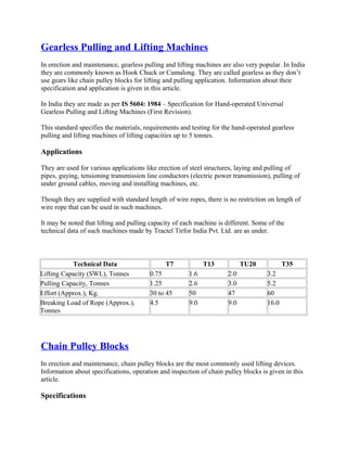
  • 1. Gearless Pulling and Lifting Machines In erection and maintenance, gearless pulling and lifting machines are also very popular. In India they are commonly known as Hook Chuck or Cumalong. They are called gearless as they don’t use gears like chain pulley blocks for lifting and pulling application. Information about their specification and application is given in this article. In India they are made as per IS 5604: 1984 – Specification for Hand-operated Universal Gearless Pulling and Lifting Machines (First Revision). This standard specifies the materials, requirements and testing for the hand-operated gearless pulling and lifting machines of lifting capacities up to 5 tonnes. Applications They are used for various applications like erection of steel structures, laying and pulling of pipes, guying, tensioning transmission line conductors (electric power transmission), pulling of under ground cables, moving and installing machines, etc. Though they are supplied with standard length of wire ropes, there is no restriction on length of wire rope that can be used in such machines. It may be noted that lifting and pulling capacity of each machine is different. Some of the technical data of such machines made by Tractel Tirfor India Pvt. Ltd. are as under. Technical Data T7 T13 TU20 T35 Lifting Capacity (SWL), Tonnes 0.75 1.6 2.0 3.2 Pulling Capacity, Tonnes 1.25 2.6 3.0 5.2 Effort (Approx.), Kg. 30 to 45 50 47 60 Breaking Load of Rope (Approx.), Tonnes 4.5 9.0 9.0 16.0 Chain Pulley Blocks In erection and maintenance, chain pulley blocks are the most commonly used lifting devices. Information about specifications, operation and inspection of chain pulley blocks is given in this article. Specifications
  • 2. ANSI/ASME B30.16-2007 Overhead Hoists (Underhung) ASME B30.16 applies to the construction, installation, operation, inspection, testing, and maintenance of hand chain-operated chain hoists and electric and air-powered chain and wire ropes hoists used for, but not limited to, vertical lifting and lowering of freely suspended, unguided, loads which consist of equipment and materials. Indian Standard In India, chain pulley blocks are made as per IS 3832: 2005 (Hand-Operated Chain Pulley Blocks – Specification). This standard lays down the general requirements and testing of the hand-operated chain pulley blocks, worm or spur gear type. They are tested at 50% overload as specified in the standard. They are generally provided with alloy steel load chain as per IS 6216: 1982. This standard prescribes the requirements for lifting chains, Grade T (8), accurately calibrated for use as load chains in pulley blocks and other lifting appliances. These are electrically welded round steel short link chains, fully heat-treated and tested and comply with the general conditions of acceptance of IS 5616: 1982. Design safety factor shall be 4.0 or more. Specifications for a chain pulley block include following items. • Lifting Capacity (Safe Working Load). • Number of falls of load chain. • Effort on hand chain to raise safe working load. • Weight of Chain pulley block assembly for 3.0 meter lift. • Extra weight for each additional meter lift. Effort on hand chain to raise safe working load by one reputed Indian manufacturer for various capacity of chain pulley blocks is as under. Lifting Capacity in Kg. 500 1000 2000 3000 5000 8000 10000 Effort on Hand Chain in Kg. 20 36 38 36 45 52 48 Light chain pulley blocks and chain blocks requiring less pull on hand chain may be selected for easy of operation.
  • 3. Operation and Inspection Check and verify that structure or other equipment (e.g. travelling trolley) that will support the chain pulley block has a rated load capacity equal to or greater than the rated load capacity of the chain pulley block to be used. Operation • Check that chain is properly seated in sheaves and that chain is not twisted, kinked, or damaged. • Don’t wrap chain around load or use chain as a sling. • Don’t leave load suspended when chain block is unattended unless specific precautions have been instituted and are in place. Inspection Inspect break mechanism, load chain and hook as under. Break Mechanism Break is of self actuated screw and disc type. Brakes require more than audible-visual inspection. Check frequently by stopping chain block with / without load at various positions to test holding power and amount of drift. If drift is noticed, adjust break. Periodically check evidence of worn, glazed, or oil-contaminated friction discs; worn pawls, cams or ratchet; corroded, stretched, or broken pawl springs. Load Chain Inspect contact points for excessive wear. One manufacturer has suggested to measure inside length of 5 links under light tension using a caliper-type gauge. They have recommended replacing the chain if measurement exceeds maximum allowable gauge length as given below. Chain Wire Diameter in mm Normal Length of 5 Links in mm Maximum Length of 5 Links in mm
  • 4. 5.0 75 77.6 6.3 95 98.3 7.1 105 108.6 8.0 120 124.1 9.0 135 139.6 Hooks Hook requires replacement because of excessive bends, twists, or throat opening indicating abuse or overloading. Check for cracks (dye penetrant, magnetic particle, or other suitable detection method). Remove the crack if superficial by grinding. Replace the hook if it is deep. Hook must be replaced when throat opening measurement has increased 5% over the original throat opening dimension of a new hook. A bend or twist of the hook exceeding 10 degrees from the plane of the unbent hook requires replacement. Measure hooks depth at load bearing point (base, bowl or saddle). Hook must be replaced when wear at load bearing point is 10% of the original depth of the hook load bearing point. Caution: Never repair hooks by welding or reshaping. Heat applied to the hook will alter the original heat treatment of the hook material and reduce the strength of the hook. Rigging Hardware – Wire Rope Clips Wire rope clips serve as an alternative to splicing and are a simple mechanical means of securing a wire rope round a thimble. They are also known as Bulldog Clips or wire rope clamps. Information about specification and method of installing wire rope clips is given in this article. Wire rope clips are made from two types of materials. They are malleable iron and drop forged steel. Malleable wire rope clips are to be used only for non-critical, light duty applications with small applied loads. They should not be used for lifting or suspending load. Specifications Wire rope clips are made as per Federal Specification FF-C-450D and ASME B30.26. As per Federal Specification, they are classified as under.
  • 5. Type I: Single grip, single saddle, with U-bolts and nuts. They are made in two classes. Class 1 – Steel saddle. Class 2 – Malleable iron saddle. Type II: Double grip, double saddle, with U-bolt and nuts. Type III: Double grip, double saddle, with bolt and nuts. They are made in two classes. Class 1: Assembled with integral L-shaped bolts and nuts. Class 2: Assembled with separate hex head bolts and nuts. Type IV: Double grip, two taper threaded half clamps with hexagon nut. Type I and Type III clips are widely used in the industry. Type III clips having double saddle design eliminates the possibility of incorrect installation. For dimensional detail, please refer the specification or Crosby’s General Catalog. For elevator, personnel hoist, and scaffold applications, refer ANSI A17.1 and ANSI A10.4. These standards do not recommend U-Bolt style wire rope clip terminations. For OSHA (Construction) applications, see OSHA 1926.251. Tables showing minimum number of clips to be installed, amount of wire rope required to turn back and tightening torque for various sizes of forged wire rope clips meeting performance requirements of Federal Specification FF-C-450D, Type I, Class 1 and Type III are given below. Type I, Class 1 Clips Clip Size (in.) Rope Size(mm) Minimum No. of Clips Amount of Rope to Turn Back in mm *Torque in Nm.
  • 6. 1/8 3-4 2 85 6.1 3/16 5 2 95 10.2 1/4 6-7 2 120 20.3 5/16 8 2 133 40.7 3/8 9-10 2 165 61.0 7/16 11-12 2 178 88 1/2 13 3 292 88 9/16 14-15 3 305 129 5/8 16 3 305 129 3/4 18-20 4 460 176 7/8 22 4 480 305 1 24-25 5 660 305 1-1/8 28-30 6 860 305 1-1/4 33-34 7 1120 488 1-3/8 36 7 1120 488 1-1/2 38-40 8 1370 488 1-5/8 41-42 8 1470 583 1-3/4 44-46 8 1550 800 2 48-52 8 1800 1017 2-1/4 56-58 8 1850 1017 2-1/2 62-65 9 2130 1017 2-3/4 68-72 10 2540 1017 3 75-78 10 2690 1627 3-1/2 85-90 12 3780 1627 Type III Clips Clip Size (in.) Rope Size(mm) Minimum No. of Clips Amount of Rope to Turn Back in mm *Torque in Nm. 3/16 5 2 100 40.7 1/4 6-7 2 100 40.7 5/16 8 2 127 40.7 3/8 9-10 2 133 61.0 7/16 11-12 2 165 88.1 1/2 13 3 279 88.1 9/16 14-15 3 323 176
  • 7. 5/8 16 3 342 176 3/4 18-20 3 406 305 7/8 22 4 660 305 1 24-25 5 940 305 1-1/8 28-30 5 1040 488 1-1/4 32-34 6 1400 488 1-3/8 36 6 1570 678 1-1/2 38-40 7 1980 678 *The tightening torque values shown are based upon the threads being clean, dry, and free of lubrication. Note: Above tables are reproduces from Crosby’s General Catalog. Method of Installing Wire Rope Clips When using wire rope clips, extreme care must be exercised to make certain that they are attached correctly. Failure to do so could result in serious injury or death. Carry out their installation as under. Match the same size wire rope clip to the same size rope diameter. For example, use a 3/8” wire rope clip with a 3/8” wire rope. Inspect wire rope clip nuts before and after each use. Wire rope clips should be placed on the wire rope connection with the corrugation in their saddles coinciding with the lay of the wire rope. Generally saddles are provided with right-hand helix. For wire rope with left-hand helix, use clips having left-hand helix. Making an Eye with a Thimble Turn back specified length of wire rope from thimble (please refer tables given above). Put first clip one saddle width from seized “dead end” (Figure 1). Seat “live end” (load carrying part) of wire rope in saddle and position U-bolt over “dead end.” Tighten nuts evenly to proper torque. Put the second clip as near the loop or thimble as possible (Figure 2). Install nuts firmly but do not yet tighten to proper torque. Install all remaining clips equally spaced between the first two clips (Figure 3). Install nuts firmly but do not yet tighten to proper torque.
  • 8. Apply light tension to wire rope assembly to take up rope slack and then tighten all nuts evenly to proper torque. Add at least one more clip if a pulley (sheave) is used in place of a thimble. If more clips are used than specified, proportionally increase the amount of wire rope that is turned back. If Seale construction or similar large outer wire type construction in the 6 x 19 Class is to be used for sizes 1 inch and larger, add one additional clip. After assembly, first apply load to test the assembly. This load should be of equal or greater weight than loads expected in use. Next, check and retighten nuts to recommended torque. When the required minimum number of clips are installed and nuts are tightened to required torque, the assembly will develop up to 80% efficiency for clip sizes 1/8" through 7/8" and 90 % for sizes 1" through 3-1/2" If more number of clips are used than shown in the table, the amount of turnback should be increased proportionately. Wire Rope Splicing (joining) Procedures The preferred method of splicing two wire ropes together is to use inter-locking turnback eyes with thimbles, using the recommended number of clips on each eye as shown above. An alternate method (without using thimbles) is to use twice the number of clips as used for a turnback termination as shown below. In this method the rope ends are placed parallel to each other, overlapping by twice the turnback amount. The minimum number of clips should be installed on each dead end. All other instructions given above shall be followed. In accordance with good rigging and maintenance practices, the wire rope end termination should be inspected periodically for wear, abuse, and general adequacy.
  • 9. Rigging Hardware – Turnbuckles Information about specification and application for turnbuckles is given in this article. Specification Turnbuckles are made as per Federal Specification FF-T-791b, ASME B30.26 and ASTM F- 1145. Federal Specification FF-T-791b covers swaged, welded, cast or forged turnbuckles with and without jam nuts. Three types and four form of turnbuckles are made as per this specification as under. Type I – Open turnbuckle bodies Form: 1 – Forged 2 – Spread 3 – Resistance welded and 4 – Arc or gas welded. Type II – Pipe turnbuckle bodies and Type III -Rigging turnbuckle bodies. They are made in eight classes as under. 1 – Turnbuckle, body only without end pulls, heads not drilled. 2 – Turnbuckle, body only without end pulls, heads threaded right and left hand. 3 – Turnbuckle with stub and stub end pulls, complete. 4 – Turnbuckle with eye and eye end pulls, complete. 5 – Turnbuckle with hook and hook end pulls, complete. 6 – Turnbuckle with hook and eye end pulls, complete. 7 – Turnbuckle with jaw and jaw end pulls, complete. 8 – Turnbuckle with jaw and eye end pulls, complete. Class 4 to Class 8 turnbuckles of Type I, Form 1 (Forged) are shown below.
  • 10. Turnbuckles and end pulls are made from steel of a grade which will meet recommended working load limits specified by the specification. They are made with design factor of 5:1 and recommended working load limits in Pounds for nominal outside diameter of threads in inch are as under. Size (inch) Type I, Form 1 All Others Jaw, eye or stub end pulls Hook end pulls Jaw, eye or stub end pulls Hook end pulls ¼ 500 300 310 210 5/16 700 500 540 330 3/8 1040 700 820 460 ½ 1800 1040 1500 740 5/8 2700 1600 2400 1080 ¾ 4000 2000 3600 1500 7/8 5800 2400 5000 2000 1 7600 2900 6600 2560 1 ¼ 12000 4600 10700 4120 1 3/8 14400 5800 12600 4860 1 ½ 17000 7200 15500 5860 1 ¾ 23000 - 21000 - 2 30000 - 27600 - 2 ¼ 39400 - 36200 - 2 ½ 48400 - 44600 - 2 ¾ 60800 - 55400 - 3 70000 - 67400 - 3 ¼ 80000 - 80000 -
  • 11. 3 ½ 95000 - 95000 - 3 ¾ 110000 - 110000 - 4 127000 - 127000 - Note: As steel is selected by manufacturer, turnbuckles offered by some manufacturers have higher safe working load than specified by above specification. Turnbuckles bodies and ends are available in standard lengths. For dimensional detail, please refer the specification or Crosby’s General Catalog. Application Turnbuckles are recommended for straight or in-line pull only. Generally open forged turnbuckles are used for hoisting and rigging operations. If a turnbuckle is used in an application where vibration is present, the end fittings should be secured to the frame with lock pins or wires to prevent them from turning and loosening. Lock nuts are available for all sizes of turnbuckles. Rigging Hardware – Hooks and Swivels Information about material, specification, marking and application for hooks and swivels is given in this article. Hooks Hooks are installed on cranes, hoists, etc. and are also used for rigging. Rigging hooks are used as part of rigging tackle, such as sling assemblies, or with below-the- hook lifting devices. They are available in carbon steel and alloy steel materials. They are made as per requirements of ASME B30.10 and Federal specification RR-C-271D. A latch, or mousing, bridges the throat opening of the hook for the purpose of retaining slings, chains, or similar parts under slack conditions and is not intended to support the load. Latch equipped hooks shall be used for all hoisting and rigging operations unless the application makes use of the latch impractical, or unsafe. Many styles of hooks are available. Two typical rigging hooks are shown below.
  • 12. Some rigging hooks (e.g., sorting hooks) are designed to carry the load near the point/tip as well as in the bowl or saddle of the hook. The designated SWL applies only when the load is applied in the bowl or saddle of the hook. Generally forged alloy steel hooks are used as rigging hooks. The manufacturer’s identification shall be forged or die-stamped on the hook. Application Load shall be applied in the bowl or saddle of the hook. Side loading, back loading and tip loading as shown below are conditions that damage and reduce the capacity of the hook. Inspection All hooks shall be inspected as per statutory requirements. Service Classification for Hooks Hooks fitted on cranes, hoists, etc. are classified based on service/use as under. Normal Service: Service that involves operating at less than 85% of rated load except for isolated instances. Heavy Service: Service that involves operating at 85% to 100% of rated load as a regular
  • 13. specified procedure. Severe Service: Heavy service coupled with abnormal operating condition. Hooks fitted on cranes, hoists, etc. having any of the following conditions shall be discarded. • Deformation: Any bending or twisting visible to the inspector. • Throat Opening: Any distortion causing an increase in throat opening exceeding 5% or as otherwise directed by the hook manufacturer. • Wear: Any wear exceeding 10% of the original section dimension of the hook or its load pin or as otherwise directed by the hook manufacturer. • Cracks: Any visible crack. • Latch engagement: Damaged or malfunctioning latch (if provided). • Nondestructive Testing: Hooks with a rated load greater than or equal to 10 tons and assigned to heavy or severe service shall receive an NDT by a qualified inspector. Rigging hooks shall be visually inspected for the following deficiencies before use: • Distortions such as bending, or twisting exceeding 10 degrees from the plane of the unbent hook. • Increased throat opening exceeding 15%. • Wear exceeding 10% of the original dimension. • Cracks, severe nicks, or gouges. • Hook attachment and securing means. Rigging hooks shall be inspected as a part of the slings to which they are attached. The NDT of rigging hooks is not routinely required. NDT Methods Magnetic particle testing or liquid penetrant testing methods shall be utilized to inspect for surface intersecting discontinuities (i.e., stress or fatigue cracks). NDT shall be done in accordance with the following American Society of Testing and Materials (ASTM) standards: ASTM E-709, Standard Practice for Magnetic Particle Examination. ASTM E-165, Standard Practice for Liquid Penetrant Inspection Method. For magnetic particle testing, a coil, yoke, or wet technique should be used to eliminate the possibility of prod burns or arc strikes. Repair of Hooks
  • 14. Hooks with a crack, nick, or gouge shall be repaired by grinding lengthwise, following the contour of the hook, provided that the reduction of dimension is within the permissible limits as shown below. ZONE A: Repair not required ZONE B: 10% of original dimension ZONE C: 5% of original dimension ZONE D: Follow minimum thread size chart Hooks shall not be repaired, altered, reworked, or reshaped by welding, heating, burning, or bending. QUIC-CHECK® Feature For quickly checking of hooks for deformation, Crosby provides Deformation Indicators and distance between them – AA as shown below for hoist hooks. Two markings are forged into the product, one just below the shank or eye and the other on the hook tip. This allows for measurement to determine if the throat opening has changed, thus indicating abuse or overload. It is called QUIC-CHECK® Feature by Crosby.
  • 15. If there is no marking on a hook, two punch marks may be made on a hook and distance between them recorded. Measurement of distance between them after use will show deformation if any. Barrel Hooks They are used to handle barrels/drums. They are made from forged carbon steel. They are made as per Federal Specification RR-C-271D, Type V, Class 6. Hooks made by Crosby has Working Load Limit of 1000 Kg (per pair of hooks) and has following dimensions. I D of Eye = 39.6 mm. O D of Eye = 71.4 mm Overall Length = 174 mm and Width of Lip = 73.2 mm. Swivels
  • 16. Swivels are positioning devices and are not intended to rotate under load. They are made as per Federal Specification RR-C-271D, Type VII. Swivels together with their pins shall be forged from carbon steel. They are made in three classes as shown below. Class 1: Chain Swivel Class 2: Eye and Eye Swivel and Class 3: Jaw and Eye Swivel. Rigging Hardware – Eye Bolts Information about eye bolt’s material, specification, marking and application is given in this article. Material, Specification and Marking Eye bolts are made from forged carbon steel or alloy steel. Alloy steel eye bolts are forged, quenched, and tempered with improved toughness properties, intended primarily for low- temperature applications. Carbon steel eye bolts (ASTM A489) shall have the manufacturer’s name or identification mark forged in raised characters on the surface of the eye bolt. Alloy steel eye bolts (ASTM F541) shall have the symbol “A” (denoting alloy steel) and the manufacturer’s name or identification mark forged in raised characters on the surface of the eye bolt. Eye bolts are made as per ANSI/ASME B18.15 and ASME B30.26. ASME B18.15 is limited to dimensions and capacities for forged threaded eye bolts intended primarily for lifting applications, and cover the following types and styles: Type 1, Plain Pattern (straight shank); Style A – Long Length; Style B – Short Length. Type 2, Shoulder Pattern; Style A – Long Length; Style B – Short Length. Short Length Shoulder Pattern eye bolts are also known as Machinery Type eye bolts. ASME B30.26 include identification, ductility, design factor, proof load and temperature requirements.
  • 17. Eye bolts shall have a minimum design factor of 5, based on ultimate strength. Working Load Limit shown is for in-line pull. Eye bolts manufactured in accordance with ASTM A489 (Standard Specifications for Carbon Steel Lifting Eyes) are rated for lifting service between +30°F and +275°F. These temperature limitations are also referenced in ASME B18.15 (Forged Eye bolts). Eye bolts manufactured in accordance with ASTM F 541 (Alloy Steel Eye bolts) are rated for use at a low temperature of -40°F. ASTM F 541 requires the symbol “A” to denote alloy steel. Safe Working Load for Carbon Steel Shouldered Eye bolts as per ANSI/ASME B18.15 is as under. Norminal size (in.) Inside diameter of eye (in.) Safe Working Load for Shouldered Eye bolt (lb) Vertical 30° from vertical 60° from vertical 90° from vertical 1/4 0.69 400 75 Not recommended Not recommended 3/8 0.94 1,000 400 220 180 1/2 1.12 1,840 850 520 440 5/8 1.31 2,940 1,410 890 740 3/4 1.44 4,430 2,230 1,310 1,140 1 1.69 7,880 3,850 2,630 2,320 1 1/4 2.12 12,600 6,200 4,125 3,690 1 1/2 2.44 18,260 9,010 6,040 5,460 2 3.06 32,500 15,970 10,910 9,740 Safe Working Load for Carbon Steel Eye bolts as per ASME B30.26 for vertical (in-line) loading for Inch and Metric sizes are as under. Size (in.) Working Load Limit (lbs.) 1/4 650 5/16 1,200 3/8 1,550 1/2 2,600 5/8 5,200 3/4 7,200
  • 18. 7/8 10,600 1 13,300 1-1/4 21,000 1-1/2 24,000 Metric Size Working Load Limit – kg m6 200 m8 400 m10 640 m12 1000 m16 1800 m20 2500 m24 4000 m30 6000 m36 8500 For angular lifts, adjust working load as follows: Direction of Pull Adjusted Working Load 45 degrees 30% of rated working load
  • 19. 90 degrees 25% of rated working load IS 4190: 1984 Indian standard for eye bolts is IS 4190: 1984 (Specification for Eye Bolts with Collars). This standard specifies the basic dimensions, material, lifting capacity and conditions of use of lifting eyebolts of Grade M. These eyebolts, which are described as `universal` may be used in all cases involving vertical and inclined lifting. This standard covers only eyebolts with eyes of internal diameters capable of permitting direct engagement with eyehooks of the same lifting capacity (working load limit) for use with Grade T(8) chain. In the case of eyehooks for use with Grade M(4) chain, it may be necessary to use an intermediate component such as a shackle to make the connection. Application It is recommended to use shouldered eye bolts for rigging hardware, except when prohibited by the configuration of the item to which the eye bolt is attached. Where non-shouldered eye bolts are required, they shall be used only in vertical pulls or in rigging systems that are designed, analyzed, and approved by a qualified person. For vertical loading, eye bolts without shoulders have the same load-carrying ability as shouldered eye bolts. Shoulders of eye bolts shall seat uniformly and snugly against the surface on which they bear. Never undercut eye bolt to seat shoulder against the load. Always countersink receiving hole or use washers to seat shoulder. When more than one eye bolt is used in conjunction with multiple-leg rigging, spreader bars or lifting beams should be used to eliminate angular loading. In case two or more than two eye bolts are used without spreader bars, their orientation shall be such that load is in the plane of the eyes as shown below (Orientation of eye bolts). When eye bolts cannot be properly seated and aligned with each other, a steel washer or spacer not to exceed one thread pitch may be required to put
  • 20. below the eye bolt. Proper thread engagement must be maintained. Use a washer with approximately the same diameter as the eye bolt shoulder and the smallest inside diameter that will fit the eye bolt shank. If the hook does not go completely into the eye bolt, use a shackle to avoid loading the hook tip. Installation for In-line Loading For in-line loading application use regular nut eye bolt or shoulder nut eye bolt. Use number of nuts based on thickness of load as shown below. Use one nut if thickness is more than one eye bolt diameter. Use two nuts if thickness is less than or equal to eye bolt diameter. Always tighten nuts securely against the load.
  • 21. Installation for Angular Loading Use shoulder nut eye bolt for angular loading. If the eye bolt protrudes so far through the load that the nut cannot be tightened securely against the load, use properly sized washers to take up the excess space between the nut and the load as shown below. Thickness of washers / spacer must exceed the distance between the bottom of the load and the last thread of the eye bolt. Reeving of Sling Slings shall not be reeved through an eye bolt or reeved through a pair of eye bolts. Reeving will alter the angle of loading on the eye bolt as shown below. Only one leg should be attached to each eye bolt. Machinery Eye Bolt – Installation for In-line & Angular Loading These eye bolts are primarily intended to be installed into tapped holes. For installation, tap the load (tap depth) to a minimum depth of one-half the eye bolt size beyond the shank length of the machinery eye bolt. If the plane of the machinery eye bolt is not aligned with the sling line, add
  • 22. shims (washers) of proper thickness to adjust the angle of the plane of the eye to match the sling line as shown below. To attain the rated capacity, minimum thread shank length of engagement depends on parent material and must be as follows: Steel: 1 thread diameter Cast iron, brass, bronze: 1.5 times the thread diameter Aluminum, magnesium, zinc, plastic: 2 times the thread diameter Swivel Hoist Ring Swivel hoist ring shown above is a patented product manufactured by The Crosbygroup Inc. and is available in UNC and Metric thread sizes. One of the main advantages for its use is self alignment of its eye with the load angle due to swivel movement and they are rated 100% for 90 degree angle. It gives 360° swivel and 180° pivot action as shown below.
  • 23. Eye Bolt Inspection Visually inspect each eye bolt before use. Eye bolts that are worn, cracked, bent, elongated or have damaged threads shall be discarded. Ensure that threads on shank and receiving hole are clean. Note: For more information on eye bolts (dimensions) and swivel hoist rings (different type of rings) please refer General Catalog of the Crosby Group. Acknowledgement: Sketches in this article are based on sketches in General Catalogue by Crosby Group. Rigging Hardware – Shackles In rigging various types of hardware are used to hold loads. Information about shackle’s specification and application is given in this article. Specifications Shackles are manufactured in two configurations – Anchor Shackle and Chain Shackle. They are also known as Bow Shackle and Dee Shackle. Both are available with screw pin, round pin, or bolt type as shown below.
  • 24. In USA, shackle specifications are defined by the following documents, depending on the shackle size: For shackles 3/16 to 2 3/4 inches, the specifications are derived from Federal Specification RR- C-271, “Chains and Attachments, Welded and Weldless.” For shackles 1 1/2 to 4 inches, the specifications are derived from MIL-S-24214, “Shackles, Steel, General Purpose and High Strength.” For shackles 4 1/2 to 8 1/2 inches, ASTM A148M, “Standard Specification for Steel Castings, High Strength, For Structural Purposes,” should be used. Note: For the overlaps in size, with RR-C-271 and MIL-S-24214, either specification may be used; however, RR-C-271 is most commonly used. Catalogs and manufacturers’ literature will list the federal specification number as “RR-C-271(rev.).” Two grades of shackles are made as per specification RR-C-271D. Grade A shackles, together with their pins and bolts are forged from carbon steel. Grade B shackles together with their pins and bolts are forged from alloy steel.
  • 25. Recommended safe working loads for these grades are as under. Recommended Safe Working Load (Maximum) in Pounds Size (D) inches Grade A Grade B Size (D) inches Grade A Grade B 3/16 520 900 1-1/4 16,500 36,000 1/4 710 2,000 1-3/8 19,800 41,400 5/16 1,060 3,120 1-1/2 23,740 48, 800 3/8 1,590 3,800 1-5/8 27,900 57,400 7/16 2,170 5,180 1-3/4 32,320 65,000 1/2 2,830 6,500 2 42,220 85,040 9/16 3,580 - 2-1/4 54,000 - 5/8 4,420 10,000 2-1/2 67,600 121,400 3/4 6,360 13,800 2-3/4 81,000 - 7/8 8,650 18,700 3 96,200 150,000 1 11,310 24,400 3-1/2 131,100 200,000 1-1/8 13,360 28,600 4 171,140 260,000 It may be noted that shackles are sized by the diameter of steel in the bow section rather than the pin size. The recommended safe working loads are for In-Line loading. In In-Line loading, load is applied perpendicular to pin. If load is to be applied at an angle, it must be applied in the plane of the bow as shown below. For side loading screw pin and bolt type shackles, safe working load shall be reduced as per following table.
  • 26. Angle of Side Load from Vertical (In-Line of Shackle) Adjusted Working Load Limit 0°, In-Line 100% of Rated Working Load Limit 45° from In-Line 70% of Rated Working Load Limit 90° from In-Line 50% of Rated Working Load Limit However, shackles symmetrically loaded with two leg slings having a maximum included angle of 120° as shown below can be utilized to full Working Load Limit. Design Factors: Shackles manufactured in accordance with RR-C-271 and MIL-S-24214 have a minimum design factor of 5. Shackles manufactured to the requirements of ASTM A148M have a minimum design factor of 4. Shackles for critical-lift service shall have an initial proof load test of two times the SWL (minimum). Before making a critical lift, ensure that the shackle has been proof tested. ASME specification number for shackles is B30.26. Specification number IS 6132: 2003, Forged Shackles for General Lifting Purposes – Dee Shackles and Bow Shackles is applicable in India. This Indian Standard is identical with ISO 2415: 1987 `Forged shackles for general lifting purposes – Dee shackles and bow shackles' issued by the International Organization for Standardization (ISO). ISO 2415:2004 specifies the general characteristics of forged dee and bow shackles in a range of sizes having working load limits of from 0,32 t to 100 t and in Grades 4, 6 and 8, and presents their performance and critical dimensions necessary for their interchangeability and compatibility with other components.
  • 27. Shackles by Crosby In addition to normal shackles, Crosby makes two special types of shackles as under. Wide Body Shackle Use of wide body shackles increases sling bearing surface and eliminates need for a thimble. Due to higher D/d ratio, it also increases usable sling strength. COLD TUFF® shackles They are suitable for use to -50° F. Application Select type of a shackle as under. Round Pin Shackles: They can be used in tie down, towing, suspension or lifting applications where the load is strictly applied in-line. Screw Pin Shackles: They can be used in any application where a round pin shackle is used. In addition, screw pin shackles can be used for applications involving side-loading circumstances. Reduced working load limits are required for side-loading applications. While in service, do not allow the screw pin to be rotated by a live line, such as a choker application. Bolt-Type Shackles: They can be used in any applications where round pin or screw pin shackles are used. In addition, they are recommended for permanent or long term installations and where the load may slide on the shackle pin causing the pin to rotate. Useful Information on Use of a Shackle The shackle pin shall never be replaced with a bolt; only a properly fitted pin shall be used. Bolts are not intended to take the load that is normally applied to the pin as shown below.
  • 28. Centralize whatever is being hoisted on the pin by suitable washers or spacers as shown below. Screw pin shackles shall not be used if the pin can roll under load and unscrew as shown below.
  • 29. When using a shackle to make choker hitch, place pin in the eye of sling as shown below. Slings Slings are the most commonly used piece of materials handling apparatus. They are used with material handling equipments like cranes, chain pulley blocks, etc. to hold suspended loads. Based on type of construction, there are mainly three types of slings. They are single leg sling, multiple leg sling (for bridal hitch with two, three or four legs) and end less sling (grommet type). Numerous sling end configurations and fittings/attachments are available for various applications. There are six types of slings based on material of manufacture – wire rope slings, alloy steel chain slings, synthetic web slings, synthetic round slings, metal mesh slings and fibre rope slings. Information about these slings is given in this article. Wire Rope Slings Wire rope slings are a basic material handling tool and are the most frequently used type of slings in industry. Wire rope slings are made from wire ropes with either Independent Wire Rope Core (IWRC) or a fiber core. A sling manufactured with a fiber core is usually more flexible but is less resistant to environmental damage. Sling made of an independent wire rope core has greater strength and is more resistant to heat damage. Mostly slings are made from wire rope having right hand regular lay of 6×19 or 6×37 construction. Wire rope slings are made from various grades of wire rope, but the most common grades in use are Improved Plow Steel, Extra Improved Plow Steel (EIPS) and Extra Extra Improved Plow Steel (EEIPS). Construction Slings ends are generally made with plain loops or with thimbles. Sling with Plain Loops
  • 30. Sling with plain loops at both ends is used for general purpose lifting. The sling eye shall have maximum angle of 15 º a shown above. Generally the eye dimensions are W = 8d and L = 16d where d = wire rope diameter. Sling with Thimbles Thimble (shown above) is the reinforcing member of a rope eye. It protects the rope at the point of attachment. Thimbles are fitted to sling ends to protect the rope against wear and abrasion from hooks, links, pins, etc. Heavy duty thimbles are used for protection against concentrated wear. Commonly used sling end configurations with thimbles are shown below. Sometime spelter or swaged type sockets are fitted at the end of a wire rope as shown below.
  • 31. Sling ends are made by hand splicing, mechanical splicing or by rope clips as under. Hand Splicing Hand splice is made by forming an eye and "tucking" and "locking" a strand of the wire rope under other adjacent strands (interweaving the wire rope strands). Splicing by this method requires skill, is time consuming and requires long rope. The method is now replaced by mechanical splicing. Mechanical Splicing In mechanical splicing, the end of wire rope after forming an eye is secured to the sling body (wire rope) by pressing a metal sleeve/ferrule. A hydraulic swaging press with special dies is used to bond the sleeve in place. Extreme pressure forces the sleeve material to flow into the voids between the wires and strands, creating an assembly that maintains most of the wire rope's nominal breaking strength. This type of eye is known as loop back eye. Flemish Eye In Flemish Eye, the rope firstly undergoes a limited form of hand spliceing (Flemish Splicing) which is then completed by mechanically swaging a steel sleeve/ferrule over the ends of the rope as shown below.
  • 32. Flemish eye is fabricated by unlaying the rope body into two parts, one having three strands, the other having the remaining three strands and core. The rope is unlayed far enough back to allow the eye to be formed by looping one part in one direction and the other part in the opposite direction and laying the rope back together. The strands are rolled back around the rope body and a metal sleeve is slipped over the ends and pressed (swaged) to secure the ends to the sling body. Rope Clips/Clamps It is recommended not to use wire rope clips (shown above) to fabricate wire rope slings, except where the application precludes the use of prefabricated slings and where the sling is designed for the specific application by a qualified person. It is also advised not to use slings made with wire rope clips in a choker hitch. If sling ends are fabricated by wire rope clips, they shall be made of drop forged steel and using adequate number of clips at recommended spacing. U bolt of a clip shall be fitted over the dead end of the rope and the live rope shall rest in the clip saddle. The clips shall be evenly tightened to recommended torque before and after the initial load is applied and shall be inspected regularly to ensure that the recommended torque remains. Slings fabricated using wire rope clips shall be de-rated to 80% of the rated wire rope load capacity to account for the efficiency of the clips. Swage Fittings and Spelter Sockets Above picture shows open and closed type of swage and spelter sockets. In case of swage fitting, a wire rope end is inserted into the fitting bore and swaged onto the rope (like mechanical splicing).
  • 33. In case of a spelter socket, a wire rope end is inserted in the socket and attached to it by pouring molten metal (Zinc or White Metal) or resin in the fitting basket (cup). For more information on spelter socketing procedures, please refer following standards. IS 3937: Recommendation for socketing of wire ropes (Part 1: with Zinc, Part 2: with White Metal and Part 3: with resins). ISO 7595: Socketing procedures for wire ropes―Molten metal socketing. ISO 7596: Socketing procedures for wire ropes―Resin sockting. For more information on splicing, please refer IS 5245 as under. IS 5245, Part 1: Methods for splicing of wire ropes, Part 1 – Hand splicing of wire ropes. IS 5245, Part II: Methods for splicing of wire ropes, Part II – Wire rope sling legs with Ferrule- Secured eye terminals. Braided and Cable-Laid Slings Braided Sling 8-part braided slings are fabricated from 8 pieces of small diameter wire ropes, braided together to form one large sling. They can be either flat or round. They are commonly used for high capacity lifts. They snug tightly to a load in a choker hitch, resist kinking and offer the ultimate in flexibility. Cable-Laid Sling Cable-laid slings are fabricated from a rope comprised of 7 small wire ropes. This construction creates a very pliable sling and is used where flexibility and resistance to kinking are more important than resistance to abrasion. Since the rope is made up of many smaller wire ropes, the sling can bend around smaller diameters without taking a permanent set or kink. The small wires, however, are susceptible to abrasion. Minimum Length of a Sling It is recommended to have minimum length of sling as under. Slings made of rope with 6×19 and 6×37 classifications and cable slings should have a minimum clear length of rope 10 times the component rope diameter between splices, sleeves, or end fittings. Braided slings should have a minimum clear length of rope 40 times the component rope diameter between the loops or end fittings. Grommets and endless slings should have a minimum circumferential length of 96 times the body diameter of the grommet or endless sling.
  • 34. Proof Loads Wire rope sling assemblies shall be proof tested using the following criteria: Hand Tucked: The proof load for hand-tucked slings shall be a minimum of the rated load and shall not exceed 1.25 times the rated load. Wire Rope Clips: The proof load for wire rope clip slings shall be a minimum of the rated load and shall not exceed two times the rated load. Others Configurations: The proof load for other types of slings including mechanical splice, zinc-poured, resin poured, and swaged socket shall be two times the rated load. Multiple Leg Slings: The proof load for multiple-leg bridle slings shall be applied to the individual legs. The proof load for the individual legs shall be consistent with the particular single-leg assembly stated above. Any master link to which multiple legs are connected shall be proof loaded to two times the force applied by the combined legs. D/d Ratio The capacity of a wire rope sling can be greatly affected by being bent sharply around pins, hooks, or parts of a load. The wire rope industry uses the term “D/d ratio” to express the severity of bend. “D” is diameter of curvature that the rope or sling is subjected to and “d” is the diameter of the rope. The minimum D/d ratio is usually taken as 20 which correspond to 92 % efficiency. Rated Loads / Capacity Safe Working Load (SWL) Limit / Rated Capacity of a sling depend on strength of material (wire rope), fabrication efficiency and design factor (factor of safety). Rated capacities (SWL) of commonly used single leg slings for vertical lifting expressed in Tons (2000 lb) are as given under. Rated loads in the tables are based on design factor of 5 and minimum D/d ratio of 25/1.
  • 35. Wire Rope Classification: 6×19 or 6×37 Type of Core: Fiber Core (FC) Wire Rope Grade (Tensile Strength): Extra Improved Plow Steel (EIPS) Grade Rope Diameter inch Rated Capacity in Tons (2000 lb) Hand-tucked splice Mechanical splice Swaged or poured (spelter) socket ¼ 0.54 0.56 0.60 5 /16 0.83 0.87 0.94 3 /8 1.2 1.2 1.3 7 /16 1.6 1.7 1.8 ½ 2.0 2.2 2.4 9 /16 2.5 2.7 3.0 5 /8 3.1 3.4 3.7 ¾ 4.3 4.8 5.2 7 /8 5.7 6.6 7.1 1 7.4 8.3 9.2 1 1 /8 9.3 10 12 1 1 /4 11 13 14 Wire Rope Classification: 6×19 or 6×37 Type of Core: Independent Wire Rope Core (IWRC) Wire Rope Grade (Tensile Strength): Extra Improved Plow Steel (EIPS) Grade Rope Diameter inch Rated Capacity in Tons (2000 lb) Hand-tucked splice Mechanical splice Swaged or poured (spelter) socket ¼ 0.54 0.65 0.68 5 /16 0.83 1.0 1.1 3 /8 1.2 1.4 1.5 7 /16 1.6 1.9 2.0 ½ 2.0 2.5 2.7 9 /16 2.5 3.2 3.4 5 /8 3.1 3.9 4.1
  • 36. ¾ 4.3 5.6 5.9 7 /8 5.7 7.6 8.0 1 7.4 9.8 10 1 1 /8 9.3 12 13 1 1 /4 11 15 16 1 3 /8 14 18 19 1 ½ 16 21 23 1 5 /8 19 24 26 1 ¾ 22 28 31 1 7 /8 25 32 35 2 28 37 40 Wire Rope Classification: 6×19 or 6×37 Type of Core: Independent Wire Rope Core (IWRC) Wire Rope Grade (Tensile Strength): Extra Extra Improved Plow Steel (EEIPS) Grade Rope Diameter inch Rated Capacity in Tons (2000 lb) Hand-tucked splice Mechanical splice Swaged or poured (spelter) socket ¼ 0.60 0.71 0.74 5 /16 0.92 1.1 1.2 3 /8 1.3 1.6 1.7 7 /16 1.7 2.1 2.2 ½ 2.2 2.8 2.9 9 /16 2.8 3.5 3.7 5 /8 3.4 4.3 4.5 ¾ 4.7 6.2 6.5 7 /8 6.2 8.3 8.8 1 8.1 11 11 1 1 /8 10 - 14 1 1 /4 13 - 18 1 3 /8 15 - 21 1 ½ 18 - 25 1 5 /8 21 - 29 1 ¾ 24 - 34
  • 37. 1 7 /8 27 - 38 2 31 - 43 Indian sling manufacturers generally offer following two types of mechanically spliced slings in wire rope construction 6×19 or 6×37. 1. Wire rope with fibre core made from galvanized wire as per Grade 1570 (160 Kgf / mm2 ). 2. Wire rope with steel core made from black wire as per Grade 1770 (180 Kgf / mm2 = Improved Plow Steel). Rated capacities (SWL) of these single leg slings for vertical lifting expressed in Tonne (1000 Kgf) based on design factor of 5 are as under. Rope Diameter mm Safe Working Load in Tonnes (1 Tonne = 1000 Kgf) Galvanized wire as per Grade 1570 Black wire as per Grade 1770 6 0.32 - 7 0.43 - 8 0.57 0.81 9 0.72 1.04 10 0.89 1.2 11 1.1 1.5 12 1.3 1.8 13 1.5 2.1 14 1.7 2.5 16 2.3 3.2 18 2.9 4.1 20 3.6 5.1 2 4. 6.2 24 5.1 7.4 26 6.0 8.6 28 7.0 10.0 32 9.1 13.1 36 - 16.6 40 - 20.5 44 - 24.8 48 - 29.5
  • 38. 52 - 34.8 Note: Generally wire rope of 6×19 classification is used for wire rope diameter up to and including 1 inch. For wire rope diameter larger than 1 inch, 6×37 classification is used. IS 2762: Specification for wire rope slings and sling legs covers dimensions, construction, loading, tests and marking of one-, two-, three- and four-leg slings for wire ropes of nominal diameter 8 to 44 mm, having legs of following types: a) Single part spliced, b) Double part spliced endless, and c) Double part grommet. To get lighter slings, please specify wire rope with independent wire rope core (IWRC) made from wires having higher tensile strength (say 220 Kgf /mm2 which is equivalent to grade 2160 / Extra Extra Improved Plow Steel Grade) and factor of safety = 5. Construction Safety Association of Ontario recommends to use wire rope slings made from from improved plow steel with independent wire rope core to reduce the risk of crushing. Attachments Various types of attachments like link, hook, swivel hook, plate lifting clamp, etc. are attached to sling eyes for various applications. When two or more slings are connected to a common link for make a lifting bridal, the assembly is called multiple leg sling. Above picture shows two, three and four leg slings with oblong link and eye hooks. Three and four leg slings are used for level lifting of a load.
  • 39. When using a multiple leg sling, ensure that the rating shown for the single leg sling is not exceeded in any leg of the multiple leg sling. All attachments shall have a rated capacity equal to or greater than that of the wire rope sling. Ensure that all welded end attachments are tested by the manufacturer or equivalent entity at twice their rated capacity before initial use. Effect of Environment Permanently remove from service fiber core wire rope slings of any grade if they are exposed to temperatures in excess of 180º F (82º C). Follow the recommendations of the sling manufacturer when you use metallic core wire rope slings of any grade at temperatures above 400º F (204º C) or below minus 40º F (minus 40º C). Inspection and Removal Make periodic inspections of slings at intervals not greater than 12 months. Do not inspect a sling by passing bare hands over the wire rope body. Broken wires, if present, may puncture the hands. Deterioration that would result in loss of original strength shall be observed. Remove sling from service if any of the following conditions are present: • Severe localized abrasion or scraping of one-third the original diameter of outside individual wires. • Kinking, crushing, bird caging or any other damage resulting in distortion of the rope structure. • Evidence of heat damage. • End attachments that are cracked, deformed, or worn to the extent that the strength of the sling is substantially affected. • Severe corrosion of the rope or end attachments. • For strand-laid and single-part slings, ten randomly distributed broken wires in one rope lay or five broken wires in one strand in one rope lay. • Broken wires in braided and cable-laid slings as per table given below. Sling body Allowable broken wires per lay or one braid Allowable broken strands per sling length Less than eight-part braid 20 1 Eight-part braid and 40 1
  • 40. more Cable laid 20 1 Recommendations on Use of Wire Rope Slings Use wire rope slings with independent wire rope core (IWRC) to reduce the risk of crushing. All eyes be fitted with thimbles and formed by Flemish Splice and secured by swaged or pressed ferrules/sleeves (mechanical splicing). Flemish Eye has reserve strength in case of failure of ferrule/sleeve. Wire rope slings shall not be shortened or lengthened by knotting or twisting or with wire rope clips or other methods not approved by the sling manufacturer. Do not subject fiber core wire rope slings to degreasing or to a solvent because of possible damage to the core. Wire rope wedge sockets shall not be used to fabricate wire rope slings. Go to Top Alloy Steel Chain Slings Chain slings are used for application requiring flexibility and resistance to abrasion, cutting and high temperatures. Construction and Rated Loads Chain slings used for overhead lifting applications must be manufactured from alloy steel. Alloy steel chain slings are made from various grades of alloy, but the most common grades in use are grades 80 and 100. Rated loads for alloy steel chain slings shall be based on a minimum design factor of 4. If other grades of chain are used, use them in accordance with the manufacturer's recommendations and guidance. The general configuration of a chain sling is as shown below.
  • 41. Rated loads (with Design Factor = 4) for vertical lift of single leg alloy steel Grade 80 and Grade 100 chain slings are as shown under. Nominal Chain Size Rated Load in lb inch mm Alloy Steel Chain Grade 80 Alloy Steel Chain Grade 100 7/32 5.5 2,100 2,700 9/32 7 3,500 4,300 5/16 8 4,500 5,700 3/8 10 7,100 8,800 1/2 13 12,000 15,000 5/8 16 18,100 22,600 3/4 20 28,300 35,300 7/8 22 34,200 42,700 1 26 47,700 - 1-1/4 32 72,300 -
  • 42. Note: As per Construction Safety Association of Ontario, like all other slings and attachments, chain slings and attachments must have design factor (factor of safety) of 5. IS 2760: Specification for steel chain slings covers the requirements, methods of rating and testing of single-, two-, three- and four-leg or branch welded chain slings of Grades L (3), M (4), S (6) and T (8) using chains conforming to IS 2429 : Part I : 1970, IS 3109 : Part I : 1970, IS 6217 : 1971 and IS 6215 : 1971 respectively together with the appropriate range of components. Attachments All attachments shall have a rated capacity at least equal to that of the steel chain with which they are used. All welded components in the sling assembly shall be proof-load tested as components or as part of the sling assembly. Where used, handles shall be welded to the master link or hook before heat treatment (This prohibits welding on chain slings during field operations.). Effect of Temperature If the chain sling gets heated to a temperature above 400°F (204°C), rated loads shall be reduced in accordance with the chain manufacturer’s recommendations regarding usage both while heated and after being heated. If chain slings are to be used in temperatures of -40°F (-40°C) or less, the manufacturer should be consulted. Typical reduction of chain sling’s rated load (Safe Working Load) according to temperature is as under. Temperature Grade of Chain Grade 80 Grade 100 (°F) (°C) Temporary Reduction of Rated Load WHILE AT Temperature Permanent Reduction of Rated Load AFTER EXPOSURE to Temperature Temporary Reduction of Rated Load WHILE AT Temperature Permanent Reduction of Rated Load AFTER EXPOSURE to Temperature Below 400 Below 204 NONE NONE NONE NONE 400 204 10% None 15% None 500 260 15% None 25% 5%
  • 43. 600 316 20% 5% 30% 15% 700 371 30% 10% 40% 20% 800 427 40% 15% 50% 25% 900 482 50% 20% 60% 30% 1000 538 60% 25% 70% 35% Over 1000 Over 538 REMOVE FROM SERVICE Inspection, Repairing / Reconditioning and Removal Make periodic inspections of steel chain slings at intervals no greater than 12 months. Make a thorough inspection of slings and attachments. Look for wear, defective welds, nicks, cracks, breaks, gouges, stretch, bends, discoloration due to excessive heat, excessive pitting or corrosion, throat opening of hooks, etc. Minimum allowable thickness at any point on a link is as under. Nominal Chain or Coupling Link Size Minimum Allowable Thickness at Any Point on The Link Inch mm Inch mm 7/32 5.5 0.189 4.80 9/32 7 0.239 6.07 5/16 8 0.273 6.93 3/8 10 0.342 8.69 1/2 13 0.443 11.26
  • 44. 5/8 16 0.546 13.87 3/4 20 0.687 17.45 7/8 22 0.750 19.05 1 26 0.887 22.53 1 1/4 32 1.091 27.71 Note: Minimum allowable chain thickness is approximately 12 % reduction in diameter. Use damaged slings only after they are repaired / reconditioned and proof tested by the sling manufacturer or a qualified person. Alloy steel chain, attachments, and coupling links used for repair shall conform to the strength requirements and other requirements of the original sling. It is recommended to replace rather than repair cracked, broken, or bent links. Recommendations on Use of Chain Slings Slings should be padded to prevent links from being bent and to protect the load. Chain links and attachments shall hinge freely with adjacent links. Chain slings shall not be shortened or lengthened by knotting, twisting, or other methods as shown below. Go to Top Synthetic Web Slings Synthetic web slings are light and flexible. They are fabricated by sewing woven synthetic webbing of nylon or polyester (Dacron) yarns. They are often selected when expensive, highly polished, fragile or delicate loads are to be lifted. The softness of the web will not mar, deface or scratch loads, while its flexibility assures a firm, secure grip around the item being lifted. Web slings have the ability to elongate, absorbing and minimizing the effects of shock loads. Nylon is resistant to many alkalis where as polyester is resistant to many acids. Since they are non-
  • 45. sparking, they can be safely used in explosive atmospheres. Nylon slings are more common but polyester slings are often recommended where headroom is limited since they stretch only half as much as nylon slings. Synthetic web slings may be coated with suitable material to improve abrasion resistance, protection from sunlight or ultraviolet degradation, seal out moisture, and prevent grit from penetrating the web and causing internal wear. Construction and Rated Loads Slings can be fabricated from single or multiple plies, may include accessories such as edge guard, wear pads or sleeves, and are available in several configurations as under. Type I Sling made with a triangle fitting on one end and a slotted triangle choker fitting on the other end. It can be used in a vertical, basket, or choker hitch. Type II Sling made with a triangle fitting on both ends. It can be used in a vertical or basket hitch only. Type III Sling made with flat loop eye on each end with loop eye opening on same plane as sling body. This type of sling is sometimes called a flat eye-and-eye, eye-and-eye, or double-eye sling. Type IV Sling made with both loop eyes formed as in Type III, except that the loop eyes are turned to form a loop eye which is at a right angle to the plane of the sling body. This type of sling is commonly referred to as a twisted-eye sling. Type V Endless sling, sometimes referred to as a grommet. It is a continuous loop formed by joining the ends of the webbing together. Type VI
  • 46. Return-eye (reversed-eye) sling is formed by using multiple widths of webbing held edge-to- edge. A wear pad is attached on one or both sides of the sling body and on one or both sides of the loop eyes to form a loop eye at each end which is at a right angle to the plane of the sling body. Synthetic web slings are made from two class of stuffer weave construction webbing with a minimum certified tensile strength per inch of width of the webbing as under. Class 5 Webbing – 6800 pounds. Class 7 Webbing – 9800 pounds. Rated loads for Type I, II, III and IV single leg slings for vertical lift for various constructions are as under. Width inch Rated Load in Pounds One-ply Class 5 Webbing Two-ply Class 5 Webbing One-ply Class 7 Webbing Two-ply Class 7 Webbing Four-ply Class 7 Webbing 1 1,100 2,200 1,600 3,100 5,500 1 1/2 1,600 3,300 2,300 4,700 - 1 3/4 1,900 3,800 2,700 5,400 - 2 2,200 4,400 3,100 6,200 11,000 3 3,300 6,600 4,700 8,800 16,450 4 4,400 8,200 6,200 11,000 20,400 5 5,500 10,200 7,800 13,700 25,500 6 6,600 12,300 9,300 16,500 30,600 Note: For Type VI slings, consult the manufacturer for rated loads The rated capacity of synthetic web slings is based on the tensile strength of the webbing, a factor of safety of 5, and fabrication efficiency. Fabrication efficiency is typically 80 % to 85 % for single-ply slings but will be lower for multi-ply slings and very wide slings. For slings made from other type of construction, select them based on rated load shown on sling identification. Synthetic webbing materials other than nylon and polyester are also used and the manufacturer should be consulted for specific data for proper use. Sling Attachments If synthetic web slings incorporate metal fittings, the fittings shall have the following properties:
  • 47. • Materials are compatible with the mechanical and environmental requirements of the sling. • Fittings have a rated load at least the same as the synthetic webbing sling. • They shall have sufficient strength to sustain twice the rated load of the sling without permanent deformation and a minimum breaking strength equal to five times the rated capacity of the sling. • Surfaces shall be cleanly finished and sharp edges removed to prevent damage to the webbing. To protect slings against wear and cutting due to repeated use against sharp corners, they are fitted with protective devices like buffer strips, edge guards and sleeve or sliding tube wear pads. Effects of Environment Certain synthetic materials perform better than others in specific applications and environments. Consult the sling manufacturer or a qualified person for a specific application or before using in and around chemical environments. High radiation or chemically active environments can destroy the strength of synthetic web slings. Specific environmental limits are as follows: Do not use nylon and polyester slings in contact with objects or at temperatures in excess of 194º F (90º C), or below minus 40º F (minus 40º C). Synthetic slings made from Kevlar (Kevlar is a registered trademark of DuPont de Nemours.), K- Spec (K-Spec is a registered trademark of SlingMax.) and nylon may be used in radiation areas when the responsible person ensures that the absorbed dose do not exceed 100,000 rad during the life of the sling. Nylon web slings shall not be used where fumes, vapors, sprays, mists or liquids of acids are present. Polyester web slings shall not be used where fumes, vapors, sprays, mists, or liquids of caustics are present. Synthetic web slings are not recommended where extensive exposure to sunlight or ultraviolet light is experienced. Store slings in an area where they will not be subjected to mechanical, chemical, or ultraviolet damage, or to extreme temperatures. Inspection and Removal Criteria Inspection should be made by the person handling the sling each day the sling is used. Periodic inspection shall be carried out at least annually by a qualified inspector.
  • 48. Sling need replacement if cuts, holes, tears, broken stitching, worn eyes and worn or corroded or distorted fittings, burns from acid, caustics or heat are found. Caution on Use of Synthetic Web Slings When using sling in bridle and basket configurations, they should be used with extreme caution. At low sling angles one edge of the web will be overloaded and the sling will tend to tear as shown below. Go to Top Synthetic Round Slings Synthetic round slings also offer a number of advantages like synthetic web slings. They offer one additional advantage in that their jackets shield the fibre against ultraviolet degradation. A round sling is also easy to inspect and evaluate – if its jacket is damaged, take it out of service. Round slings have larger capacities than synthetic web slings of the same width. They can therefore be narrower. Synthetic round slings are identified by Size Numbers adopted by the Web Sling and Tie Down Association to describe a slings or by Colour but always select them based on the vertical rated load shown on the sling identification.
  • 49. Go to Top Metal Mesh Slings Metal mesh slings are widely used in metalworking and in other industries where loads are abrasive, hot, or will tend to cut web slings. Unlike nylon and wire rope slings, metal mesh slings resist abrasion and cutting. Metal mesh slings grip the load firmly without extensive stretching. Construction and Rated Loads Material for Fabric Construction: Carbon Steel. Fabric Construction Heavy Duty Medium Duty Light Duty Nominal spiral turns per foot mesh width 35 43 59 Approx. spiral wire size 10 gage 12 gage 14 gage Equivalent decimal size 0.135 in. 0.105 in. 0.080 in. Nominal cross rods per foot of fabric length 21 30 38 Approx. size of cross rods 8 gage 10 gage 14 gage Equivalent decimal size 0.162 in. 0.135 in. 0.080 in. Nominal fabric thickness 1/2 in. 3/8 in. 5/16 in. Rated loads of Metal Mesh Slings based on Design Factor = 5 for vertical and choker lift are as under. Width inch Rated Loads in Pounds (lbs) Heavy Duty Medium Duty Light Duty 2 1,600 1,450 900
  • 50. 3 3,000 2,170 1,400 4 4,400 2,900 2,000 6 6,600 4,800 3,000 8 8,800 6,400 4,000 10 11,000 8,000 5,000 12 13,200 9,600 6,000 14 15,400 11,200 7,000 16 17,600 12,800 8,000 18 19,800 13,500 9,000 20 22,000 15,000 10,000 Metal mesh slings are also made from materials other than carbon steel. They are made from alloy steel for higher rated loads and stainless steel for corrosive environments. Effect of Environment Metal mesh slings can be used without a rated load reduction in temperatures ranging from minus 20º F (minus 29º C) to 550º F (288º C) except elastomer-coated slings. Use elastomer- coated slings in temperature ranges of 0º F (minus 18º C) to 200º F (93º C). Inspection Make periodic inspections of metal mesh slings at intervals not greater than 12 months. Look for following items. • Broken wires in any part of the mesh. • Broken weld or broken brazed joint along the sling edge. • Reduction in wire diameter of 25 percent or more due to abrasion or 15 percent or more due to corrosion. • Lack of flexibility due to distortion of the mesh. • Pitted, corroded, cracked, bent, twisted, gouged, or broken fittings. Go to Top Natural and Synthetic Fibre Rope Slings
  • 51. Slings manufactured from conventional three-strand natural or synthetic fiber rope are not recommended for use in lifting service. Natural or synthetic fiber rope slings shall be used only if other sling types are not suitable for the unique application. Rated loads for synthetic fibre rope slings based on Design Factor = 5 and vertical lift are as under. Rope Diameter inch Rated Loads for Vertical Lift in Pounds (lbs) Nylon Polyester Polypropylene 1/2 1,100 1,000 760 9/16 1,400 1,300 920 5/8 1,800 1,600 1,100 3/4 2,600 2,200 1,500 7/8 3,500 3,000 2,100 1 4,400 4,000 2,600 1 1/8 5,700 5,000 3,200 1 1/4 7,000 6,000 3,900 1 5/16 7,700 6,500 4,200 1 1/2 9,700 8,400 5,500 1 5/8 11,500 9,900 6,400 1 3/4 13,200 11,400 7,400 2 16,900 14,400 9,400 2 1/8 19,100 16,200 10,500 2 1/4 21,400 18,100 11,900 2 1/2 26,300 22,000 14,400 2 5/8 28,800 24,200 16,100 3 37,100 31,200 20,500 D/d ratio for rope slings shall be larger than 8/1. Go to Top General Recommendations on Use of Slings
  • 52. All types of slings shall have, as a minimum, the rated capacity clearly and permanently marked on each sling. Each sling shall receive a documented inspection at least annually, more frequently if recommended by the manufacturer or made necessary by service conditions. Wire rope slings shall be labeled with a tag or other identification methods similar to one shown below. When repaired, a sling shall be permanently marked to identify the repairing agency. New and repaired / reconditioned slings including welded components shall be proof load tested by the sling manufacturer or repair agency. Replace hooks that have been opened more than 15% of the normal throat opening measured at the narrowest point or twisted more than 10° from the plane of the unbent hook. Ensure that in a choker hitch, the choke point is only on the sling body, never on a fitting. Do not rest loads on the sling. Do not pull a sling from under a load when the load is resting on the sling. Do not drag slings on the floor or over abrasive surfaces. For more information on slings please refer ANSI/ASME B30.9.