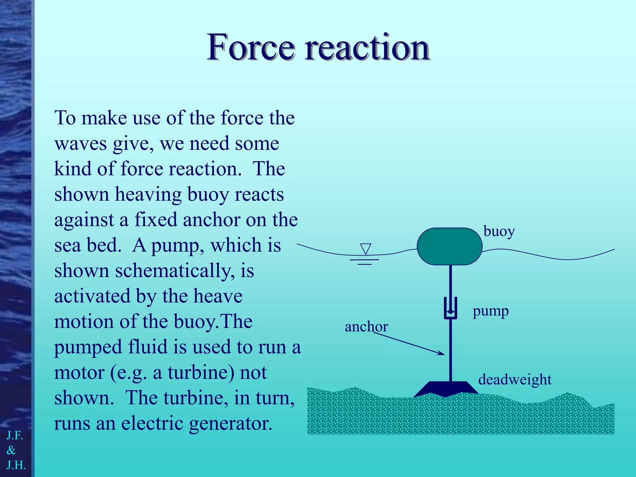
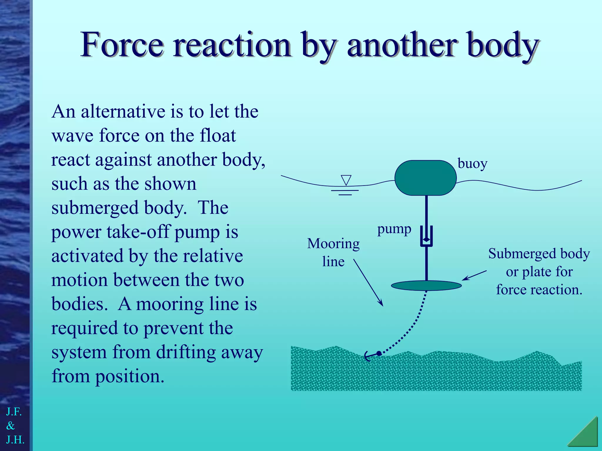
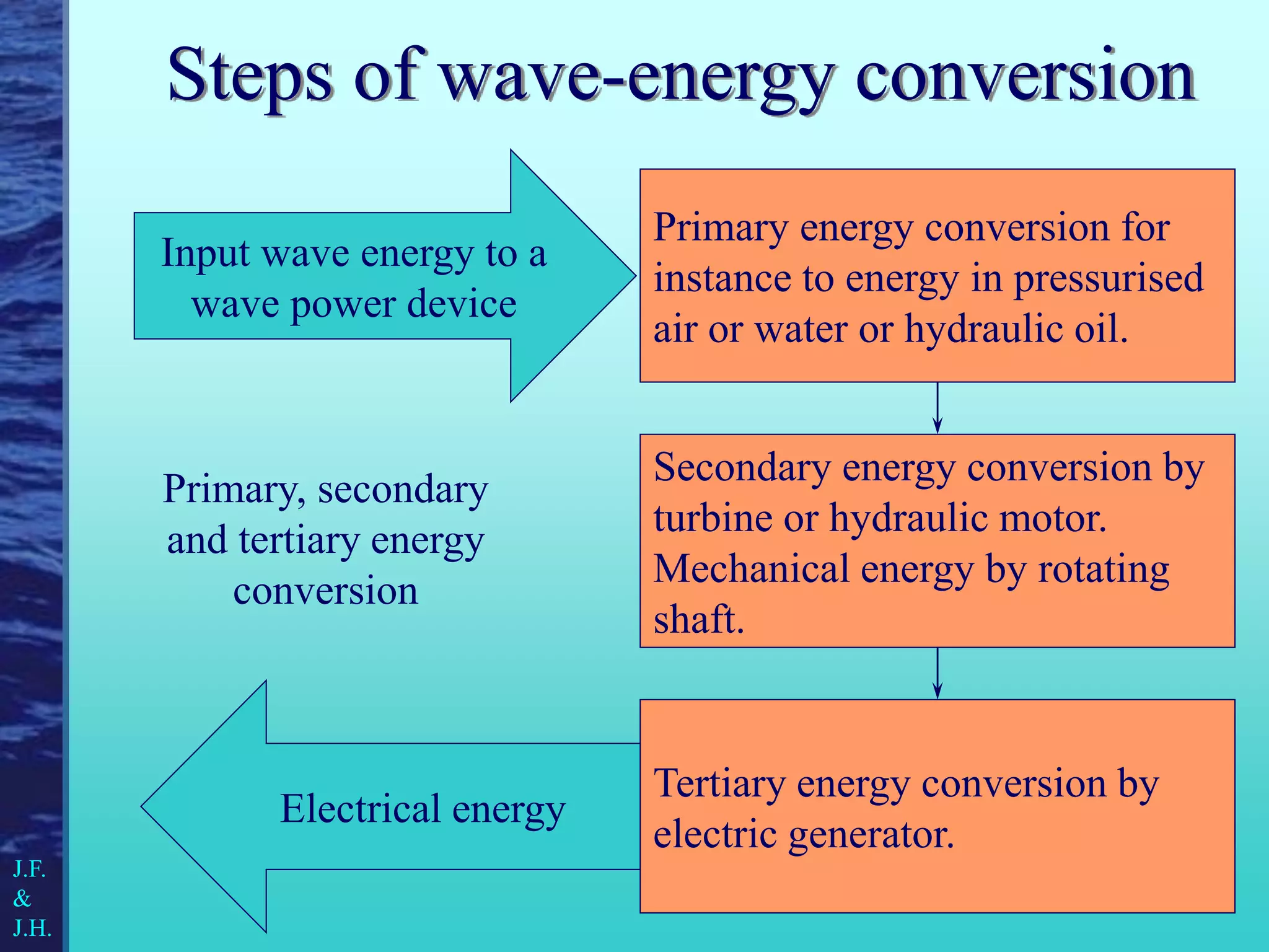
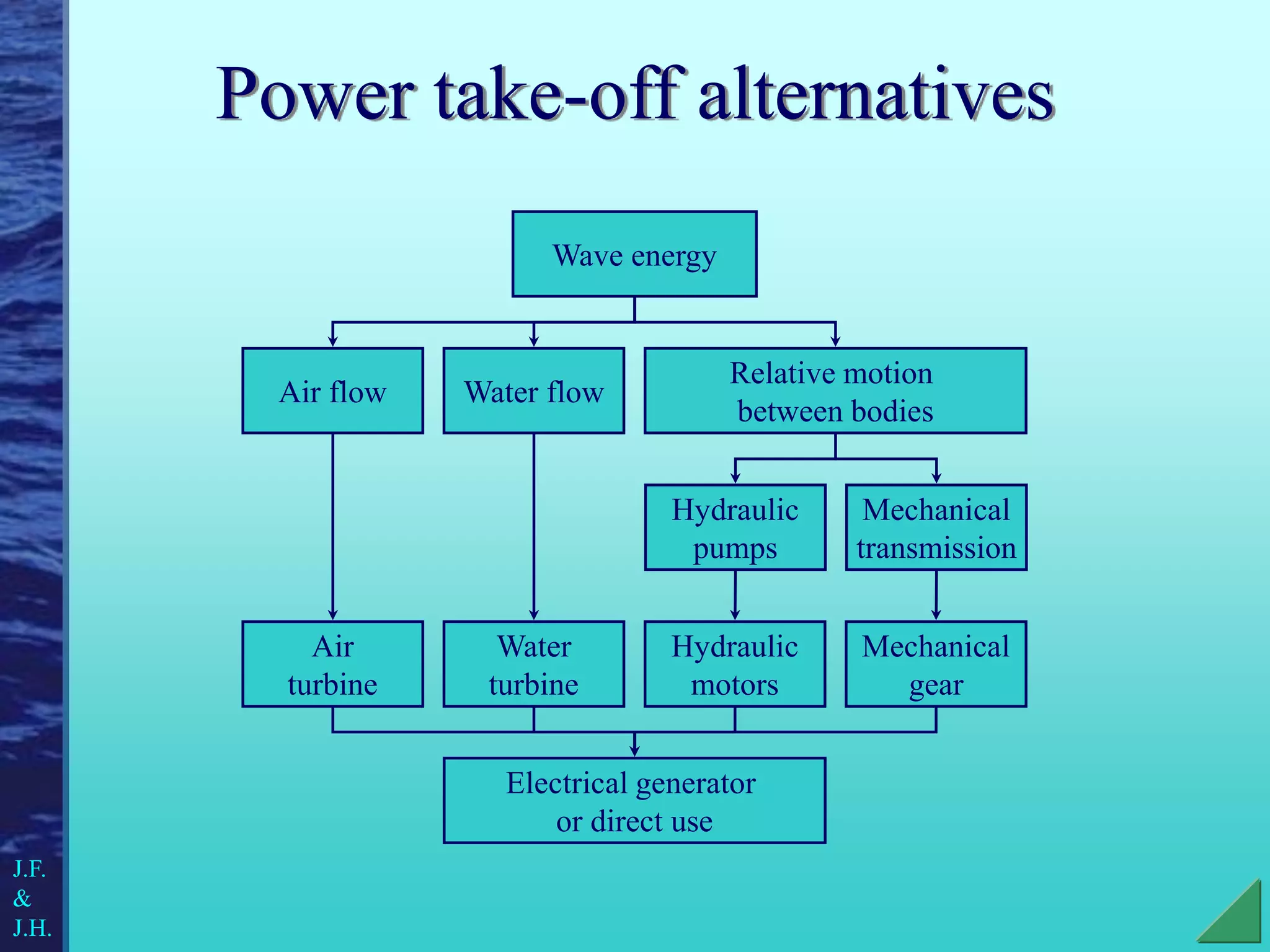
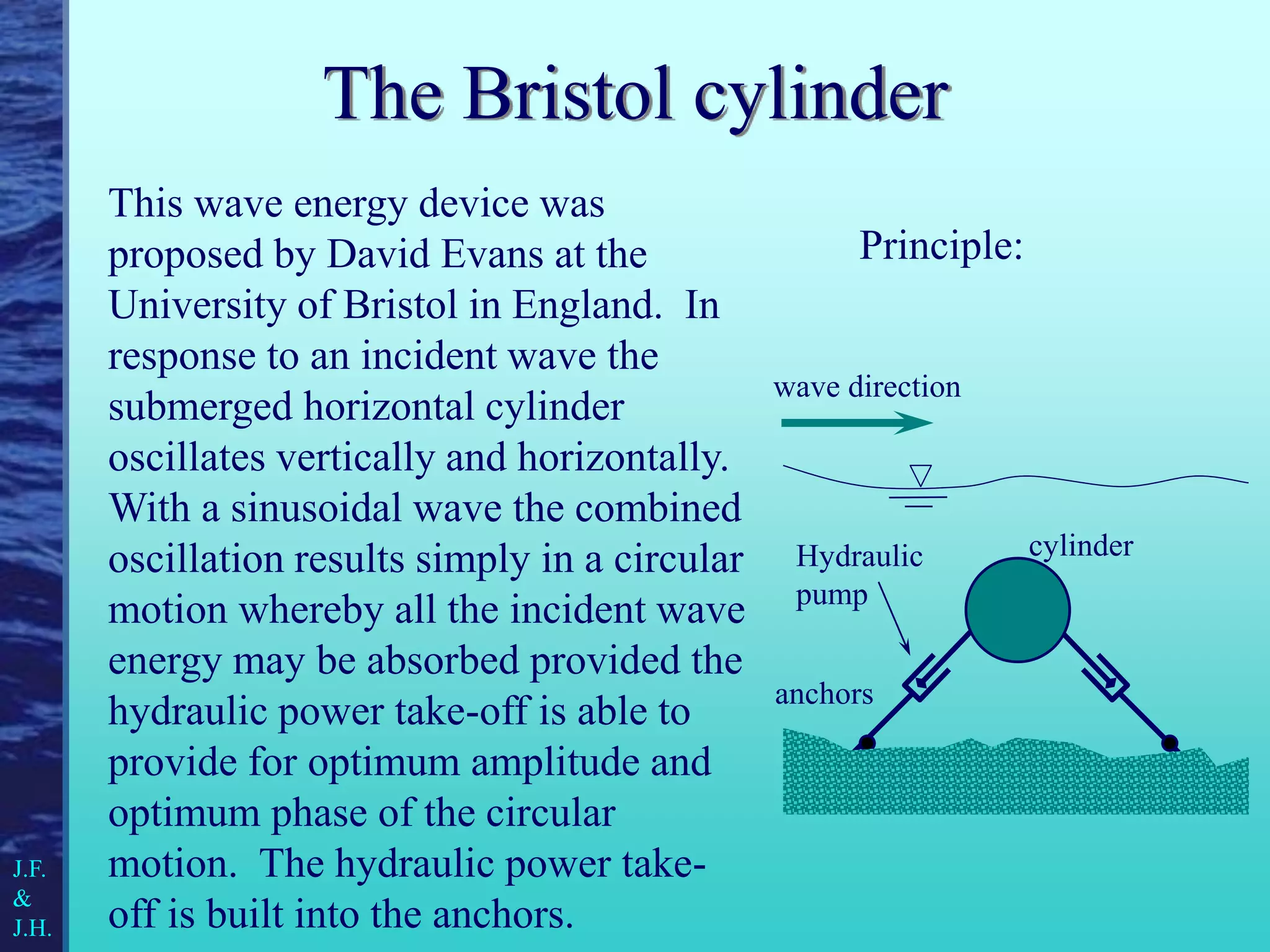
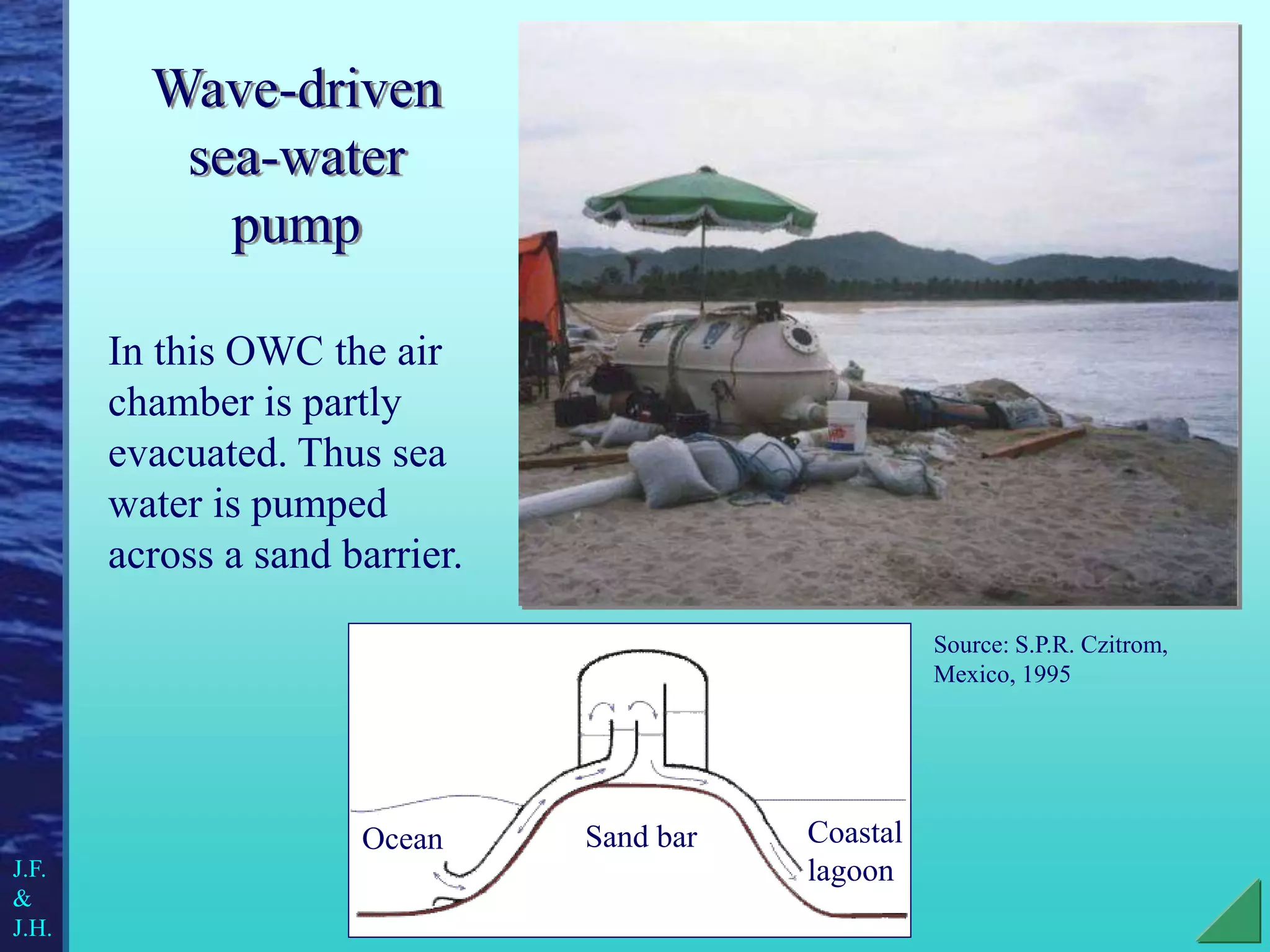
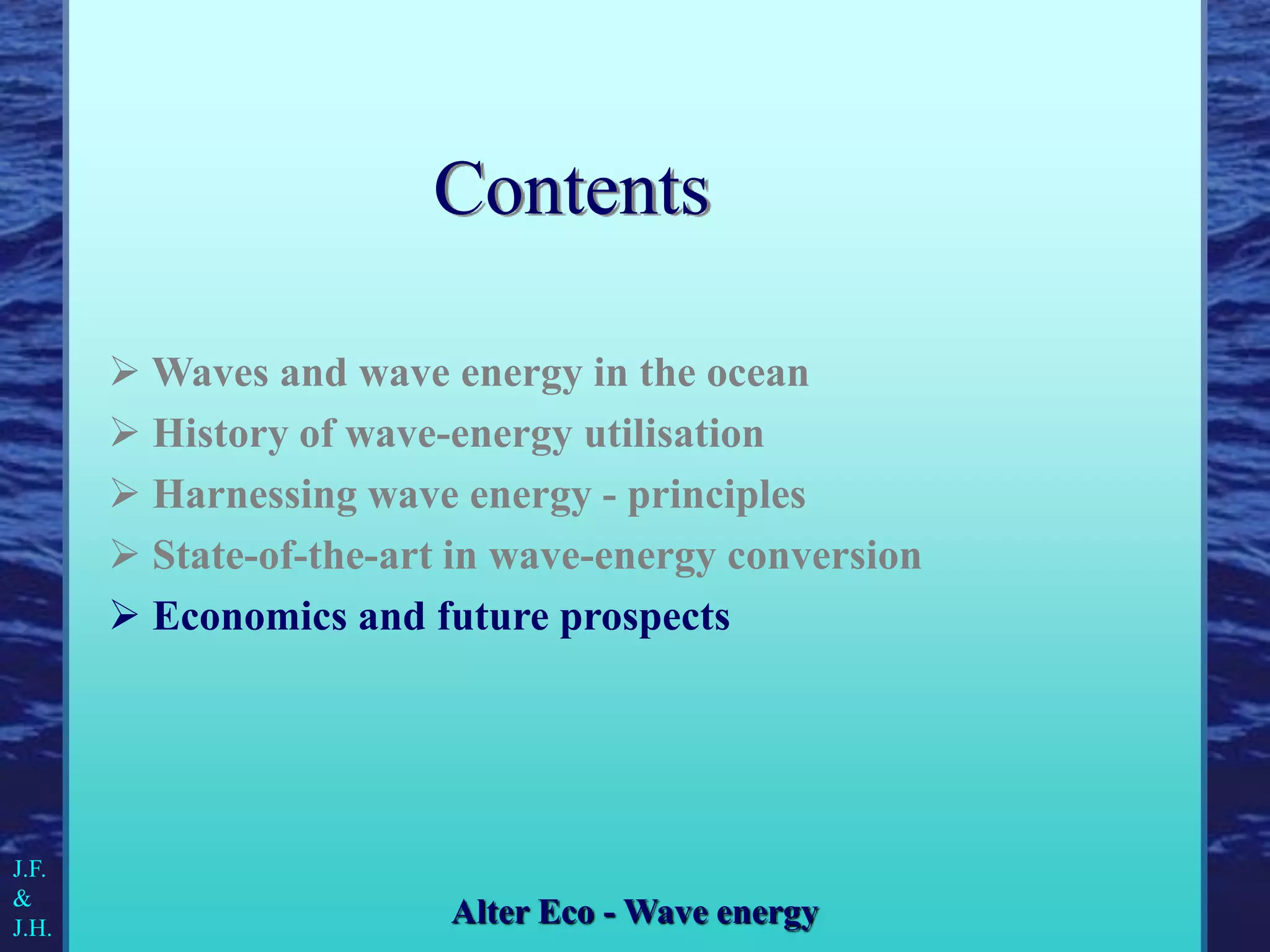
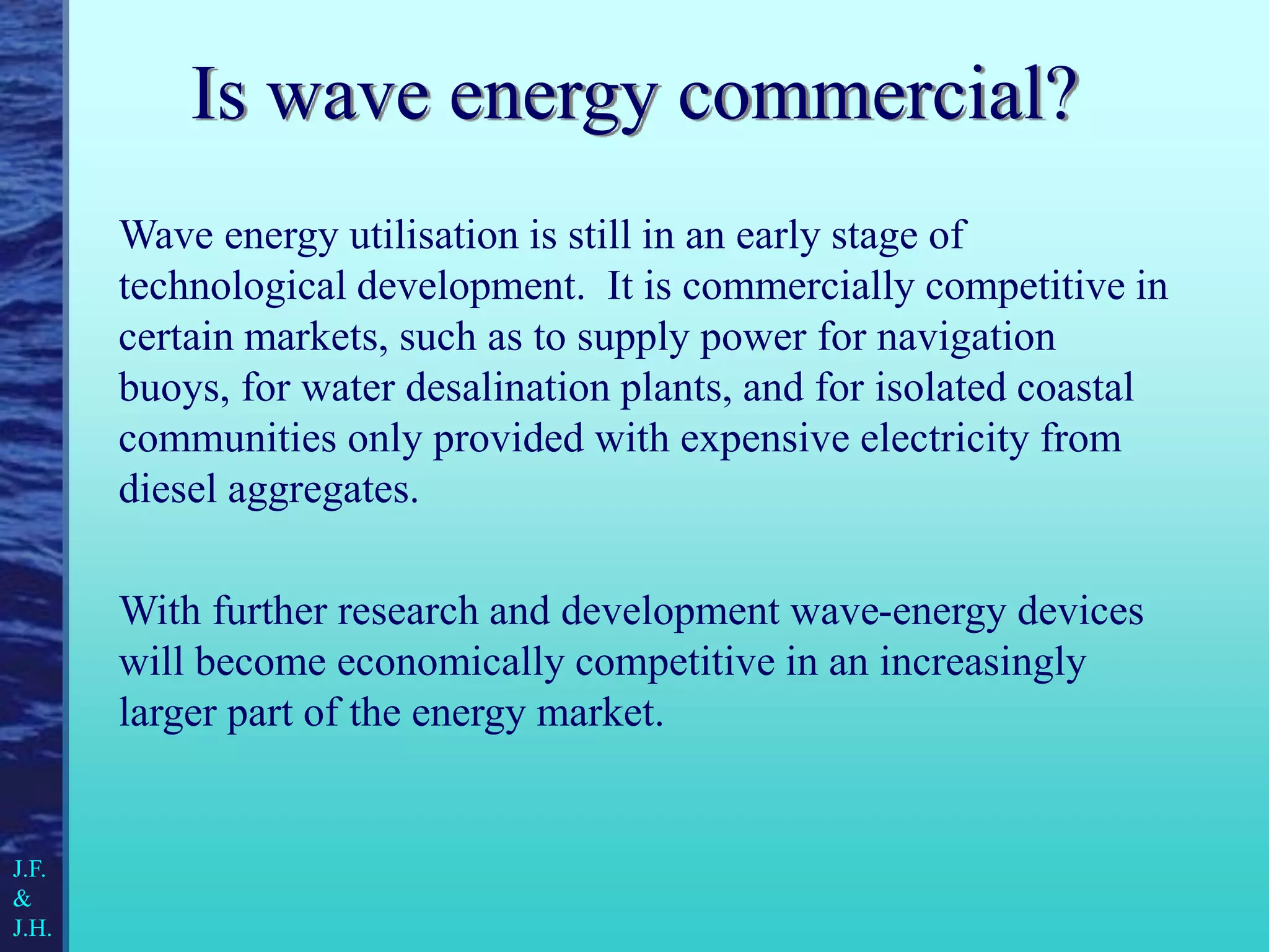
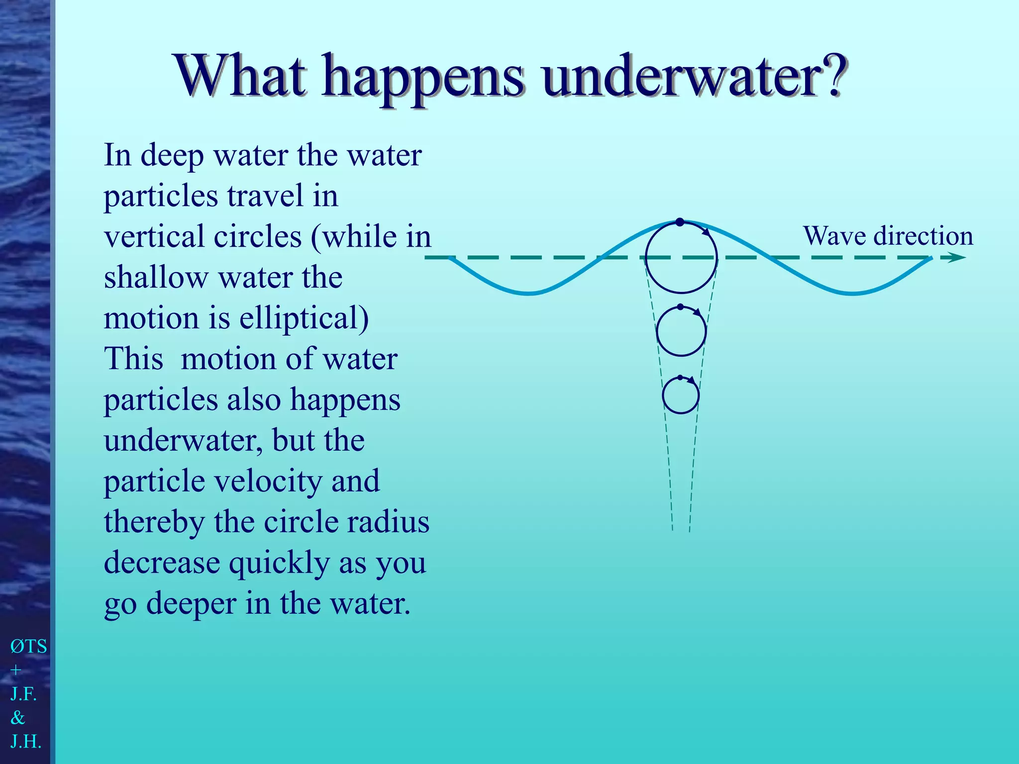
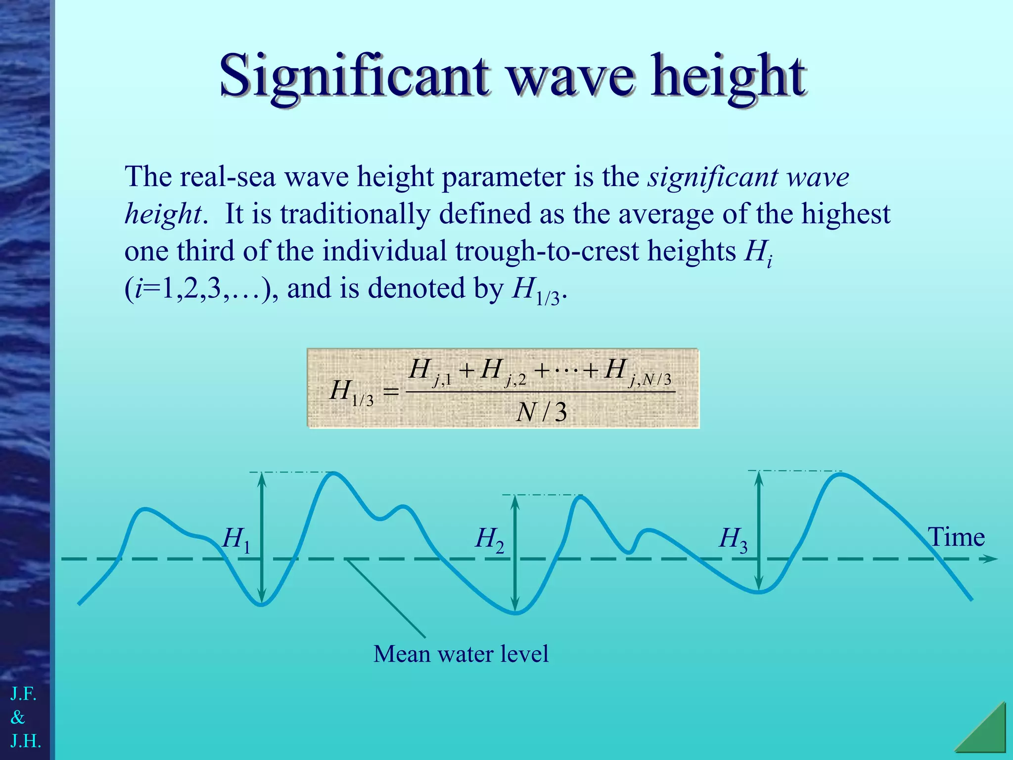
This is a slide collection made for educational purposes as part of the EU Leonardo pilot project 1860 Alter ECO in 1999.
Authors: Johannes Falnes and Jørgen Hals Todalshaug
1. Trondheim, June 1999 Internet: www.ntnu.no/ DOI: 10.13140/RG.2.2.19207.68003
J. Falnes and J. Hals
WAVE ENERGY AND ITS
UTILISATION:
A contribution to the EU Leonardo
pilot project 1860
Alter ECO
NTNU
Noregs teknisk-naturvitskaplege
universitet
Fakultet for fysikk,
informatikk og matematikk
Institutt for fysikk
2. Waves and wave energy in the ocean
History of wave-energy utilisation
Harnessing wave energy - principles
State-of-the-art in wave-energy conversion
Economics and future prospects
J.F.
&
J.H.
Alter Eco - Wave energy
Contents
3. The wave energy resource
Wave energy is a non-polluting and renewable source
of energy, created by natural conversion of part of the
wind energy above the oceans. Wind energy is created
by natural conversion of part of the solar energy. With
both of these energy conversions the flow of energy is
concentrated. Just below the ocean's water surface the
wave energy flow, in time-average, is typically five
times denser than the wind energy flow 20 m above the
sea surface, and 10 to 30 times denser than the solar
energy flow. Hence, there are good prospects for
development of commercial wave-power plants, which
may in the future become significant components for
providing energy to many coastal nations.
J.F.
&
J.H.
4. What is a wave?
Everyone has seen waves on lakes or oceans. Waves are
actually a form of energy. Energy, not water, moves along the
ocean's surface. The water particles only travel in small
circles as a wave passes.
Wave direction
Snapshot of the water surface at a certain instant:
ØTS
+
J.F.
&
J.H.
5. How to describe a wave
Wave direction
Snapshot of the water surface at a certain instant:
Wavelength L
Wave height H
Amplitude A
Crest
Trough
J.F.
&
J.H.
6. Surface elevation versus time
At a fixed position in space:
Wave period T
Time
Frequency f = 1 / T
J.F.
&
J.H.
7. Generating a wave
When the wind blows across a smooth water surface, air
particles from the wind grab the water molecules they
touch. The force or friction between the air and water
stretches the water surface, resulting in small ripples,
known as capillary waves (L less than a few centimetres).
As the wind continues to blow the waves grow bigger. We
call these waves gravity waves because their potential
energy is due to the gravity force of the earth.
WIND
LAND
HEAT
OCEAN
ØTS
+
J.F.
&
J.H.
8. Wind waves and swells
Waves generated by wind are called wind waves. When
the waves propagate outside their region of generation,
they are called swells. Where the water is deep, swells can
travel very large distances, for instance across oceans,
almost without loss of energy.
J.F.
&
J.H.
9. What happens underwater?
In deep water the water
particles travel in
vertical circles (while in
shallow water the
motion is elliptical)
This motion of water
particles also happens
underwater, but the
particle velocity and
thereby the circle radius
decrease quickly as you
go deeper in the water.
Wave direction
ØTS
+
J.F.
&
J.H.
10. Wave velocities
The energy in the
waves travel with the
group velocity cg. The
individual waves travel
faster - they are born
on the rear end of the
group, and they die in
the front end. On deep
water this phase
velocity is twice the
group velocity:
T
g
c
c g
2
2
= (1.56 m/s2) ·T
J.F.
&
J.H.
Time step 1
Time step 2
Time step 3
11. Circular waves from a stone dropped into a calm lake
- a simple wave experiment
Photo: Magne Falnes
J.F.
&
J.H.
12. Swells propagating across the
Pacific
Since the group
velocity is proportional
to the period, low-
frequency waves move
faster away from a
storm centre than high-
frequency waves. The
figure shows the
situation 4 days after a
storm with centre
located at 170º east and
50º south.
T = 20 s
T = 18 s
T = 16 s
T = 14 s
T = 12 s
T = 10 s
Period
-10
-20
-30
-40
180 190 200
Source: OCEANOR, Norway
J.F.
&
J.H.
13. How can waves be energy?
The best way to understand waves as energy is to
think of a long rope laid on the ground. If you pick up
one end and give it a good snap - there is a ripple
effect all the way to the other end - just like the waves
on the ocean! Energy applied at one end moves to the
other end, just like sea waves transport energy from
storm centres to distant shores - or as electromagnetic
waves transport energy form the sun to the earth.
ØTS
+
J.F.
&
J.H.
14. Energy content of waves
For a sinusoidal wave of height H, the average energy E
stored on a horizontal square metre of the water surface is:
Half of this is potential energy due to the weight of the water
lifted from wave troughs to wave crests. The remaining half
is kinetic energy due to the motion of the water.
2
H
k
E E
2
s/m
kW
5
2m
:
Example
E
H
kE = g / 8 = 1.25 kW ·s/m2
= mass density of sea water 1020 kg/m3
g = acceleration of gravity 9.8 m/s2
J.F.
&
J.H.
15. Energy transport in waves
The energy transport per metre width of the wave front is
2
TH
k
J J
kW/m
40
2m
and
s
10
:
Example
J
H
T
E
c
J g
On deep water the group velocity is cg=gT/4, which gives
kJ = g2 / 32 1 kW/m3s
J.F.
&
J.H.
16. Real sea waves
The waves on the ocean are more irregular than a sinusoidal
wave. Swells resemble sinusoidal waves more than the
chaotic, locally generated wind waves.
By courtesy of National Oceanic and Atmospheric Administration/Department of Commerce, USA
J.F.
&
J.H.
17. Significant wave height
The real-sea wave height parameter is the significant wave
height. It is traditionally defined as the average of the highest
one third of the individual trough-to-crest heights Hi
(i=1,2,3,…), and is denoted by H1/3.
3
/
3
/
,
2
,
1
,
3
/
1
N
H
H
H
H
N
j
j
j
Time
H1 H2 H3
Mean water level
J.F.
&
J.H.
18. Average zero up-cross time Tz
The individual zero up-cross time Ti is the time interval between
two consecutive instants where the wave elevation crosses the zero
level in the upward direction. An average of these over a certain
time provides a useful measure of the real-sea wave period.
N
T
T
T
T N
z
2
1
Time
T1 T2 T3
J.F.
&
J.H.
19. Measurement buoys are used
to record the sea wave
parameters at different
locations. Such physical
measurements have been
performed during the last few
decades. A typical wave
measurement lasts for about
20 min. and is repeated every
3 hours.
Measuring waves
Photo: OCEANOR, Norway
J.F.
&
J.H.
20. Real sea waves as
a combination of
sinusoidal waves
Real sea waves contain a
mixture of waves with different
directions, frequencies and
wave heights. Hence,
statistical versions of the wave
parameters are used to describe
the waves.
By courtesy of Naval Oceanographic Office, USA
J.F.
&
J.H.
21. Wave spectrum
A quantity derived from wave measurements is the so-called
energy spectrum S(f). It tells us how much energy is carried
by the different frequency components in the real-sea
“mixture” of waves. For a sinusoidal wave the average stored
energy was given by
For a real sea wave we have instead
8
/
2
H
g
E
16
/
d
)
(
2
0
s
H
g
f
f
S
g
E
J.F.
&
J.H.
22. Wave energy transport in terms of
significant wave height
Here Hs is the modern definition of significant wave
height, which in practice agrees quite well with our
previous definition H1/3. Another quantity, the so-called
wave energy period TJ, may be derived from the wave
spectrum S( f ). The energy transport by real sea waves is
now calculated by
2
)
2
/
( s
J
J H
T
k
J
3
m
kW/s
5
.
0
2
/
J
k
16
/
d
)
(
2
0
s
H
f
f
S
J.F.
&
J.H.
23. A measurement example
This time series (above) from high
sea shows that individual waves
vary greatly in size and form. The
corresponding energy spectrum is
shown to the right. For this storm
wave the significant wave height is
Hs = 8 m.
0 1 2 3 4 5 6 7 8 9 10 11 12
-6
-4
-2
0
2
4
6
-6
0
50
100
150
0.0 0.1 0.2 0.3
S ( f )
Frequency [Hz]
Time [minutes]
Surface
elevation
[m]
Source: OCEANOR, Norway
J.F.
&
J.H.
24. 0.0 0.1 0.2 0.3
0
5
10
15
S ( f )
Frequency [Hz]
0
50
100
150
0.0 0.1 0.2 0.3
S ( f )
Frequency [Hz]
These are typical energy
spectra from wind-sea
conditions (top) and mixed
wind-sea and swell
conditions (bottom).
The swells contain lower
frequencies (high peak)
than the wind waves (low
peak).
Significant wave heights:
8 m (top) and 3 m (bottom)
Real-sea spectra
J.F.
&
J.H.
Source: OCEANOR, Norway
25. Distribution of wave energy transport
Average wave power levels are approximate and given in kW/m of the wave front.
70
30
40
30
60
40
40
50
40
40
20
60
50
22
40
15
20
24
40
50
74
30
50
100
92
82
19
12
21
23
12
18
17
34
66
34
14
8 8
27
84
37
9
10
20
48
81
30
11
100
67
13
13
11
3
41
72
50
49
89
26
17
15
17
25
24
33
29
97
72
42
16
11
13
12
102
68 53
13 10
14
12
18
19
10
24
43
20
43
41
33
J.F.
&
J.H.
26. Seasonal variation
The average values of wave-energy transport vary somewhat
from one year to the next. The values vary more between
seasons.
On the northern hemisphere, the average values for
November and May may differ by a factor of two or more.
We measure significantly more wind and wave energy in
winter than in summer, although it is opposite for solar
energy.
Because there may be waves (swells) even in the absence of
wind, wave energy is more persistent than wind energy.
J.F.
&
J.H.
27. Seasonal variation at (57° N, 9° W )
The chart shows the
seasonal variation of
wave energy transport
at a measurement site
close to Barra in the
Hebrides off the
Scottish coast. The
annual average for the
shown year was 65
kW/m. 0
20
40
60
80
100
120
140
160
kW/m
Jan
Mar
May
Jul
Sep
Nov
J.F.
&
J.H.
Based on WERATLAS, European Wave
Energy Atlas, 1996
28. As we have seen, the
water particles move in
circles with decreasing
radius in the depth.
Consequently, the energy
flow density decreases as
we go deeper in the
water. In fact, on deep
water, 95 % of the energy
transport takes place
between the surface and
the depth L/4. (L is the
wavelength).
J.F.
&
J.H.
Vertical distribution of wave-energy transport
Depth
2
4
6
8
3,0 kW/m2
1,3 kW/m2
10 m
Water level
H = 2 m and T = 10 s
29. Waves and wave energy in the ocean
History of wave-energy utilisation
Harnessing wave energy - principles
State-of-the-art in wave-energy conversion
Economics and future prospects
J.F.
&
J.H.
Alter Eco - Wave energy
Contents
30. Historical review on wave
energy research
J.F.
&
J.H.
Man has always been impressed by the force of the
waves, and has been stimulated to search for possible
ways of exploiting this “ocean of energy”. Since the
first patent in 1799 over 1000 patents on wave energy
devices have been registered in Japan, North America
and Western Europe (340 were filed in the UK alone
before 1973).
31. The first patent we know
of to utilise the energy
of ocean waves dates
from 1799 and was filed
in Paris by the Girards,
father and son, who had
observed that waves
could lift very large
ships.
However, many
centuries earlier,
Polynesians had
discovered that they
could utilise ocean
waves for surfing (!).
J.F.
&
J.H.
32. Photo source: National Oceanic and Atmospheric Administration/National Marine Fisheries Service, USA
J.F.
&
J.H.
“Waves can lift ships”
33. In 19th century proposals,
the oscillating motion is
transmitted to pumps or other
suitable energy conversion
machinery by mechanical
means (such as racks and
pinions, ratchet wheels, ropes
and levers). The figure
shows a float moving up and
down. Cog wheels (not
shown) are engaged by cog
rods rigidly connected to the
float.
From a 57-page review paper in 1892 by A.W.
Stahl, The utilization of the power of ocean
waves.
J.F.
&
J.H.
34. At present, wave energy is
widely used for powering
navigation buoys. This is
an old idea, but it was first
successfully realised in
1965, after a study by the
Japan Research and
Development Corporation,
after which a Japanese
company (Ryokuseisha)
produced about 1200 buoys
for world-wide use.
Front page of a 1901 issue of the Norwegian
children’s magazine Magne. It talks about
“Electrical light buoys” for navigation.
J.F.
&
J.H.
35. An early practical
application of wave power
was a device constructed
around 1910 at Royan,
near Bordeaux in France.
Here, Mr. Bochaux-
Praceique supplied his
house with 1 kW of light
and power from a turbine,
driven by air which was
pumped by the oscillations
of the sea water in a
vertical bore hole in a cliff.
Drawing from 1920 showing Mr. Bochaux-
Praceique’s device. Reprinted with permission of
Power Magazine, The McGraw Hill Companies.
J.F.
&
J.H.
36. From Power, January 17, 1911. Reprinted with permission
of Power Magazine, The McGraw Hill Companies.
An American “wave motor”
built by The United States
Wave Power Company was
reported in an edition of the
magazine Power in 1911. It
was described as “the latest
thing in wave motors”,
although the author had
doubts about its capacity. In
the end of the article he
writes:
“This is the crux of the wave motor situation. Can such a
device be built for a cost that will permit its use in competition
with established sources of power?”
J.F.
&
J.H.
37. At about the time of the first world war petroleum became the
modern source of energy and conquered the world market.
The interest for most other energy resources faded away. A
new growing interest for instance at wave energy was
initiated with the petroleum crisis in 1973.
J.F.
&
J.H.
38. Oscillating water column (OWC)
Wave-energy devices of the
OWC type have become
rather popular since the late
1970s. A much earlier
(1952) proposal is shown
here. Sea water enters a
hollow structure with its
lower opening submerged.
Due to wave action the
inside “water column” will
oscillate. With the shown
proposal some water at the
upper part of the “column”
is drained into an elevated
water reservoir.
From British patent No. 741494 on oscillating
water columns. Reproduced by courtesy of
Electricité de France.
J.F.
&
J.H.
39. With the oil crisis in 1973 the interest in and attention to
wave energy increased remarkably, and money were put
into research and development. Since then the activity has
been up and down, with varying grants and investments.
Although significant progress has been made in the field,
the wave power technology is still immature and further
efforts have to be made before the wave energy can be
economically profitable for general energy supply in
industrialised countries. Wave energy has, however, for
some time already been commercial in certain niches of
the energy market.
J.F.
&
J.H.
40. Yoshio Masuda
The Japanese Yoshio Masuda has since 1945 been the pioneer
of modern wave-energy development. From 1947 and
onwards he tested various types of wave energy devices in
sea. Based on Masuda’s tests a floating device has been
developed, and since 1965 several hundred units have been in
use to power navigation lights. The float is rigidly connected
to a long vertical tube. Relative motion between the tube and
its contained sea water is utilised to pump air through a
turbine which is connected to an electric generator which
charges a battery.
J.F.
&
J.H.
41. 80 m long vessel Kaimei (= sea light) for testing various
types of wave-activated air turbines.
Copyright: JAMSTEC, Japan
J.F.
&
J.H.
42. Stephen Salter
In 1973 at Edinburgh University in Scotland, Stephen
Salter was the first person to initiate university research
on wave energy utilisation. After his paper “Wave
power” was published in 1974 in Nature (Vol. 249, pp.
720-724), his name has been the most well-known
within the wave-energy research community. Professor
Salter is still very active in wave energy research and he
is advocating use of electronics and high-pressure
hydraulics for optimum power take-off.
J.F.
&
J.H.
43. The Salter duck
In 1974 Stephen Salter
published a paper on a
device which has become
known as the “Salter
duck”, the “Edinburgh
duck” or simply the
“Duck”, because the
device, in its pitching
oscillation, resembles a
nodding duck. Several
ducks share a common
spine. The relative pitch
motion between each duck
and the spine is utilised for
pumping hydraulic fluid
through a motor.
spine
duck
Mooring
line
J.F.
&
J.H.
44. During the late 1970s substantial wave-energy development
programmes were launched by governments in several
countries, in particular in the UK, Norway and Sweden. The
financial support was dramatically reduced during the early
1980s when the petroleum price became lower and when
there in the public opinion was a decreasing concern about
energy and environment problems.
J.F.
&
J.H.
45. Waves and wave energy in the ocean
History of wave-energy utilisation
Harnessing wave energy - principles
State-of-the-art in wave-energy conversion
Economics and future prospects
J.F.
&
J.H.
Alter Eco - Wave energy
Contents
46. J.F.
&
J.H.
Conversion of wave energy
The patent literature contains several hundreds of different
proposals for the utilisation of ocean-wave energy. They
may be classified in various ways into groups of, a dozen or
less, different types.
47. To make use of the force the
waves give, we need some
kind of force reaction. The
shown heaving buoy reacts
against a fixed anchor on the
sea bed. A pump, which is
shown schematically, is
activated by the heave
motion of the buoy.The
pumped fluid is used to run a
motor (e.g. a turbine) not
shown. The turbine, in turn,
runs an electric generator.
Force reaction
pump
deadweight
buoy
anchor
J.F.
&
J.H.
48. Force reaction by another body
An alternative is to let the
wave force on the float
react against another body,
such as the shown
submerged body. The
power take-off pump is
activated by the relative
motion between the two
bodies. A mooring line is
required to prevent the
system from drifting away
from position.
J.F.
&
J.H.
pump
buoy
Mooring
line
Submerged body
or plate for
force reaction.
49. Steps of wave-energy conversion
Primary energy conversion for
instance to energy in pressurised
air or water or hydraulic oil.
Secondary energy conversion by
turbine or hydraulic motor.
Mechanical energy by rotating
shaft.
Input wave energy to a
wave power device
Electrical energy
Primary, secondary
and tertiary energy
conversion
Tertiary energy conversion by
electric generator.
J.F.
&
J.H.
50. Power take-off alternatives
Wave energy
Air flow Water flow
Relative motion
between bodies
Hydraulic
pumps
Mechanical
transmission
Air
turbine
Water
turbine
Mechanical
gear
Hydraulic
motors
Electrical generator
or direct use
J.F.
&
J.H.
51. Input energy from waves
Energy in working fluid (air, water or hydraulic oil)
Electrical energy
Primary energy conversion
Turbine/motor
Electrical generator
Mechanical energy in rotating shaft
Loss
Loss
Loss
Schematic principle for extracting wave energy
ØTS
+
J.F.
&
J.H.
52. Absorption of wave energy from the sea may be considered
as a phenomenon of wave interference. Then wave energy
absorption may be described by an apparently paradoxical
statement:
To absorb a wave means to generate a wave
or, in other words:
To destroy a wave is to create a wave.
J.F.
&
J.H.
A paradox?
54. =
+
Incident wave
Wave reflected from fixed wall
Wave generation on otherwise
calm water (due to wall oscillation)
Result: The incident wave is
absorbed by the moving wall
because the reflected wave is
cancelled by the generated wave.
“To absorb a wave means to generate a wave”
- or “to destroy a wave means to create a wave”.
J.F.
&
J.H.
55. Classification of WECs
All the different proposals and principles for wave
energy conversion can be classified in several
ways. We use these in order to see the differences
and similarities between the wave energy
converters (WECs).
J.F.
&
J.H.
56. - According to size and orientation
Point absorbers Attenuator Terminator
Wave front
Wave
direction
J.F.
&
J.H.
57. - According to location
Shore-based
Near-shore bottom-
standing
Floating; near-shore or
offshore
Bottom-standing or
submerged on not too
deep water.
Submerged not far from a
water surface
Hybrid; units of types 2-5
combined with an energy
storage (such as a pressure
tank or water reservoir) and
conversion machinery on
land.
J.F.
&
J.H.
58. - According to end use of energy
• Electricity
• Desalination of sea water
• Refrigeration plants
• Pumping of clean sea water (fish farms, cleaning of
contaminated lagoons and other sea areas with
insufficient water circulation)
• Heating of sea water (e.g. for fish farms, and
swimming pools)
• Propulsion of vessels
• Combination with desired reduction of wave activity
J.F.
&
J.H.
59. - According to form of primary
energy conversion
• To hydraulic energy
• To pneumatic energy
• To mechanical energy (typical for the 19th century
proposals)
• Directly to electricity
J.F.
&
J.H.
60. Waves and wave energy in the ocean
History of wave-energy utilisation
Harnessing wave energy - principles
State-of-the-art in wave-energy conversion
Economics and future prospects
J.F.
&
J.H.
Alter Eco - Wave energy
Contents
61. The tapered channel is a
horizontal channel which is wide
towards the sea where the waves
enter and gradually narrows
towards a reservoir at the other
end. As the waves propagate along
the narrowing channel, the wave
height increases due to the
shrinking lateral space. When a
wave crest is raised to a level
exceeding the horizontal upper
edge of the channel wall, water
from the crest spills into the
elevated water reservoir.
The tapered channel
8
sea
reservoir
Principle:
J.F.
&
J.H.
62. A tapered channel
demonstration plant was built
in 1985 at Toftestallen on the
west coast of Norway. Due
to the tapering of the
horizontal channel, water is
lifted to the reservoir 3 m
above. The water in the
reservoir flows back into the
sea (behind the reservoir dam
and turbine house) through a
conventional low-pressure
water turbine running a 350
kW generator connected to
the local grid.
J.F.
&
J.H. Copyright: NORWAVE AS, Norway, 1986
NORWAVE’s TAPCHAN
63. Even on a rather calm day,
the effect of squeezing the
water in the narrowing space
of the channel results in it
gaining speed and fury,
giving an impressing view as
the water overtops the walls
and bursts into the reservoir
at Toftestallen.
Copyright: NORWAVE AS, Norway, 1986
J.F.
&
J.H.
64. Oscillating water column
(OWC)
Principle:
In an oscillating water column a
part of the ocean surface is
trapped inside a chamber which
is open to the sea below the
water line. When the internal
water surface moves up and
down in response to incident
waves outside the chamber, the
air in the chamber is pressed and
sucked through a turbine due to
the generated overpressure and
underpressure.
air
fixed platform
Turbine and generator
Waves
J.F.
&
J.H.
65. The Wells turbine
An example of a
suitable turbine for an
OWC is the so-called
Wells turbine. The
direction of the
torque is independent
of the direction of the
air flow. The Wells
turbine provides
pneumatic power
take-off for a lot of
wave-energy devices.
J.F.
&
J.H.
Copyright: JAMSTEC, Japan
66. Sanze shoreline gully
A lot of different
designs of the OWC
have been realised for
research and
demonstration purposes.
The picture shows a
Japanese OWC which
was tested at Sanze on
the west coast of Japan
in 1984. It had two
Wells turbines on each
side of a 40 kW
generator in order to
cancel the thrust forces
on the rotating shaft.
Copyright: JAMSTEC, Japan
J.F.
&
J.H.
67. Kværner Brug’s OWC
plant at Toftestallen ,
Norway
The OWC structure is
concrete below level +3,5 m
and a steel structure between
+3,5 m and +21 m. The
machinery has a vertical
shaft. The generator
housing is at the top. Below
is the (red) housing for the
self-rectifying air turbine
(500 kW).
Photo: J. Falnes, 1985.
J.F.
&
J.H.
68. Shoreline
OWC,
Isle of
Islay,
Scotland
This device was
erected by
Queens
University,
Belfast,
in a project
sponsored by the Department of Trade and Industry. The plant has
a 75 kW Wells turbine and flywheels for energy storage. The
system has been connected to the island’s grid since 1991, but is
now under decommisioning, as a new, improved design, LIMPET,
is under construction just north of the previous site (next slide).
Photo: Håvard Eidsmoen, 1993
J.F.
&
J.H.
69. LIMPET
The planned new OWC at Isle of Islay, LIMPET, with a 500
kW electric generator.
Acoustic
baffle
around
air outlet/
inlet
Wells turbine +
generator
assembly
Concrete
collector
Incoming
wave
Rock
gully
Oscillating
Water Column
Source: WAVEGEN, UK, 1999
J.F.
&
J.H.
70. LIMPET
prospects
Left: The existing
Islay OWC is seen in
the background
(right). The planned
LIMPET device (left)
has been drawn into
the photo.
Right: The 500 kW
turbine to be installed
with the new OWC.
Source: WAVEGEN, UK
Source: WAVEGEN, UK
J.F.
&
J.H.
71. The Pico
Power Plant,
Azores
An OWC pilot plant
is now (1999) being
tested on the island
of Pico, Azores.
The project is
sponsored by the European Commission (JOULE programme) and
coordinated by Instituto Superior Técnico in Portugal. It has a
bottom-standing concrete structure and a water plane area of 144
m2. The installed turbine has a rated power of 400 kW. Apart from
being a test plant, the device is supposed to provide 8-9 % of the
annual electrical energy demand of the 15 thousand islanders.
Photo: A. Sarmento, IST, Portugal, 1999
J.F.
&
J.H.
72. Air duct with turbine and air valve
for the Pico wave power plant
J.F.
&
J.H.
Photo: A. Sarmento, IST, Portugal, 1999
73. The
MIGHTY
WHALE
A full-scale
design of a
device called the
“Mighty Whale”
has been
constructed in
Japan, and now
(1999) sea trials
are carried out in
Gokasho bay. Copyright: JAMSTEC, Japan
J.F.
&
J.H.
74. Backward bent duct buoy
This buoy shape was
proposed by the Japanese
inventor and scientist Yoshio
Masuda. The waves cause the
hull to move, thereby giving
rise to a change of the water
level in the chamber. Results
from wave tank tests have
been very promising.
buoy
air
8
Principle:
mooring
J.F.
&
J.H.
air turbine
wave direction
75. Array of point absorbers
Source: SINTEF, Norway, 1982.
J.F.
&
J.H.
77. KN’s device
A proposal by Kim
Nielsen in Denmark
consists of a heaving
buoy connected to a
bottom-standing concrete
base. The motion of the
buoy pumps water out of
the chamber thus creating
under-pressure which in
turn draws water steadily
in through a turbine
which generates
electricity.
J.F.
&
J.H.
pump
buoy
8 water out
water in
through
turbine
base
rectifying valves
78. The RAMBØLL
point absorber
The Rambøll point absorber
represents a continuation of
the work with the KN device
in Denmark. A difference is
that the power take-off is in
the floating buoy instead of a
housing on the sea bed Photos: RAMBØLL, Denmark, 1998
J.F.
&
J.H.
79. Photo: Technocean, Gothenburg, Sweden, 1984
The Swedish hose pump
This Swedish heaving buoy
uses a specially designed hose
to pump sea water to high
pressure.
J.F.
&
J.H.
Float
Hosepump
Reaction Plate
Compressed Sea
Water to Generator
Sea bed
Source: Tom Thorpe, UK
80. J.F.
&
J.H.
Three hosepump units placed in the sea at Vinga, off
the Swedish west coast.
Photo: Technocean, Gothenburg, Sweden, 1984
81. The Swedish IPS buoy
Photo: Technocean, Gothenburg, Sweden, 1981
The wave-power IPS
buoy slides up and
down along a vertical
rod connected to
inertial mass some
distance down in the
water. By mechanical
or hydraulic means,
activated through the
relative motion
between the buoy and
the rod, wave energy
is converted to useful
energy.
J.F.
&
J.H.
82. Chinese navigation
light buoy
In China, wave-energy
research has been carried
out at more than ten
universities since 1980.
The picture shows a 60W
Chinese navigation light
buoy, deployed in 1985 by
Guangzhou Institute of
Energy Conversion.
Photo: Niandong Jiang, China, 1987
J.F.
&
J.H.
83. The
ConWEC
device
ConWEC is an OWC device where the
more usual air turbine is replaced by a
float with hydraulic power take-off.
J.F.
&
J.H.
Photo and figure: ConWEC, Norway, 1998
wave
direction
84. Pitching raft
A system called the McCabe Wave Pump has been designed to
produce drinking water or electricity by use of wave energy. It
has been developed by Dr. Peter McCabe and a team of engineers
from Hydam Technologies Limited in Ireland. The device makes
use of the slope change on the water surface due to waves. A 40
m long prototype was launched in the Shannon River near
Kilbaha, County Clare in Ireland in 1996.
Equipment Cabin
Bow Pontoon Aft Pontoon
Hydraulic Pumps
Central Pontoon
Steel Tubes
Damper Plate
Hinge
J.F.
&
J.H.
Source: Tom Thorpe, UK
85. The Pendulor
A new design of a device called
Pendulor is being tested (picture)
in the sea near Muroran,
Hokkaido, Japan.
Photo: Tomiji Watabe, 1999
J.F.
&
J.H.
Source: Tomiji Watabe
86. The SEA Clam
As a part of the UK Wave
Energy Programme,
research and development
have been carried out by
Coventry Polytechnic in
England. The result is a
flexible bag device called
the SEA Clam. A circular
design was tested at 1/15th
scale in the Scottish lake
Loch Ness in 1986.
Principle:
8
air
flexible bag
spine
mooring
J.F.
&
J.H.
wave direction
87. Model with 12 air
chambers, (black)
rubber membranes and
instrumentation cables
prepared for test.
Below: Model with
white rubber
membranes under test
in Loch Ness.
Test of 1:15 scale
CLAM model in
Loch Ness
Photos reproduced by permission of L.Duckers/Sea Energy Associates, UK
J.F.
&
J.H.
88. The Bristol cylinder
This wave energy device was
proposed by David Evans at the
University of Bristol in England. In
response to an incident wave the
submerged horizontal cylinder
oscillates vertically and horizontally.
With a sinusoidal wave the combined
oscillation results simply in a circular
motion whereby all the incident wave
energy may be absorbed provided the
hydraulic power take-off is able to
provide for optimum amplitude and
optimum phase of the circular
motion. The hydraulic power take-
off is built into the anchors.
Principle:
cylinder
anchors
Hydraulic
pump
J.F.
&
J.H.
wave direction
89. Wave-driven
sea-water
pump
In this OWC the air
chamber is partly
evacuated. Thus sea
water is pumped
across a sand barrier.
Sand bar Coastal
lagoon
Ocean
Source: S.P.R. Czitrom,
Mexico, 1995
J.F.
&
J.H.
90. Waves and wave energy in the ocean
History of wave-energy utilisation
Harnessing wave energy - principles
State-of-the-art in wave-energy conversion
Economics and future prospects
J.F.
&
J.H.
Alter Eco - Wave energy
Contents
91. Will these children on Rarotonga later in their lives be able to
enjoy the waves in yet another way?
Photo: J. Falnes, 1989
J.F.
&
J.H.
92. Is wave energy commercial?
Wave energy utilisation is still in an early stage of
technological development. It is commercially competitive in
certain markets, such as to supply power for navigation
buoys, for water desalination plants, and for isolated coastal
communities only provided with expensive electricity from
diesel aggregates.
With further research and development wave-energy devices
will become economically competitive in an increasingly
larger part of the energy market.
J.F.
&
J.H.
93. Cost reduction by experience
and learning
It is a well-known fact that due to experience and improved
methods of production the unit cost of a product usually
diminishes as the production volume is increased. Thus, for
electricity production in the US during 1926 to 1970 there was
a main trend of 25 % decline in the inflation-corrected price for
each doubling of the cumulative production.
For retail gasoline processing the corresponding decline was
20 %. (J.C. Fischer, Energy Crisis in Perspective, John Wiley,
New York, 1974.)
J.F.
&
J.H.
94. Estimated cost of electricity from various
OWC devices versus year of design.
0
5
10
15
20
1980 1985 1990 1995 2000
Design Year
Early Nearshore OWC
Wavegen OSPREY
Shoreline OWC
Source: Tom Thorpe, UK, 1998
J.F.
&
J.H.
Cost
of
Electricity
(pence/kWh)
95. Estimated cost of electricity from various offshore
wave-energy devices versus year of design.
1
10
100
1980 1985 1990 1995 2000
Year of Design
Cost
of
Electricity
(pence/kWh)
Edinburgh Duck
Bristol Cylinder
SEA Clam
PS Frog
McCabe Wave Pump
Sloped IPS Buoy
Source: Tom Thorpe, UK, 1998
J.F.
&
J.H.
96. Experience curve example: Estimated investment
cost (c) relative to installed power capacity versus
cumulative volume of total installed capacity (P) of
wave power plants.
c
(EUR
/
W)
Source: J. Falnes, 1995
J.F.
&
J.H.
97. Promoting new energy
technologies
During the initial stages of the development of a new energy
technology niche markets will be helpful. Otherwise,
governmental subsidies to cover the difference between cost
and market price may promote a new technology.
J.F.
&
J.H.
98. Initial handicap for new
energy technologies
Experience curves illustrate the handicap which new energy
technologies have initially, in market competition with well-
established conventional energy technologies. This fact must
be borne in mind when comparisons are made of energy cost
from new and conventional technologies. Such comparisons
would be like comparing the performance of a child with the
performance of an adult.
J.F.
&
J.H.
99. A renewable-energy/man
allegory
As a human has to grow from conception to an adult person, a
new energy production method has to develop from an idea to
mature technology. Using this analogy we may perhaps say
that wave energy is still in infancy, wind energy is a teenager
and conventional energy an adult. Let us care for the children
so they may grow up!
J.F.
&
J.H.