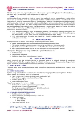
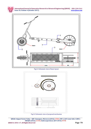
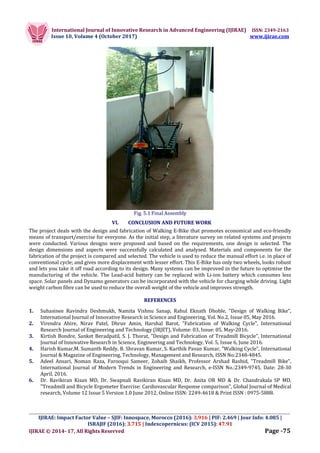
International Journal of Innovative Research in Advanced Engineering (IJIRAE) ISSN: 2349-2163
Issue 10, Volume 4 (October 2017) www.ijirae.com
_________________________________________________________________________________________________
IJIRAE: Impact Factor Value – SJIF: Innospace, Morocco (2016): 3.916 | PIF: 2.469 | Jour Info: 4.085 |
ISRAJIF (2016): 3.715 | Indexcopernicus: (ICV 2015): 47.91
IJIRAE © 2014- 17, All Rights Reserved Page -68
WALKING E-BIKE
Ajan C R, Ajay Sugadan K, Akshay Balachandran
Mechanical Engineering, University of Calicut, Kerala, INDIA
ajancr.ajancr@gmail.com; ajaysugadan@gmail.com; balachandranakshay@gmail.com;
Antony Rijo, Renji C R
Mechanical Engineering, University of Calicut, Kerala, INDIA
antonyrijojose@gmail.com; renji368@gmail.com;
Manuscript History
Number: IJIRAE/RS/Vol.04/Issue10/OCAE10091
DOI: 10.26562/IJIRAE.2017.OCAE10091
Received: 24, September 2017
Final Correction: 30, September 2017
Final Accepted: 15, October 2017
Published: October 2017
Citation: R, Ajan C, K, Ajay Sugadan, Balachandran, Akshay, Rijo, Antony and R, Renji C WALKING E-BIKE. (Issue X)
IJIRAE, Journal, eds. , University of Calicut (2017). , 1. Suhasinee Ravindra Deshmukh, Namita Vishnu Sanap, Rahul
Eknath Dhoble, "Design of Walking Bike", International Journal of Innovative Research in Science and Engineering,
Editor: Dr.A.Arul L.S, Chief Editor, IJIRAE, AM Publications, India
Copyright: ©2017 This is an open access article distributed under the terms of the Creative Commons Attribution
License, Which Permits unrestricted use, distribution, and reproduction in any medium, provided the original author
and source are credited.
Abstract— Walking E-Bike is a project which focuses on the design and fabrication of a totally new way of
moving. The idea is to create economic and ecological exercise machine/transport. The bike responds to walking
input on the treadmill belt and powers it. Alternative power is given to the wheel using a motor. The transmission
is done using a series of chain drives. The structure is well balanced and strongly built to withstand higher loads.
The motor supports the vehicle to move in difficult terrains and steep slopes.
Keywords— Treadmill, E-Bike, Eco-Transport, Hub Motor, Zero Emission
I. INTRODUCTION
Exercises are advised for health promotion and prophylaxis for many cardiovascular diseases and also for
rehabilitation after an episode of disease. Among the exercises aerobic exercises are appropriate for these
purposes. To do aerobic exercise many methods are available, For example: Running, Jogging, Walking, Cycling,
etc. Among different modes of exercises in the modern busy life, the cycling and treadmill exercises are the
commonest to perform as indoor aerobic exercises. In motor driven treadmill exercise which is similarly to
walking or jogging or running depending upon the speed of the treadmill motor is becoming more familiar to all.
1.1 TREADMILL
A treadmill is a device used for walking and running without changing the position of user. Treadmill equipment
was introduced before the development of powered machines, to harness power from animals and humans.
Machines like mills were developed which is to be driven by a person or animals by treading on a treadwheel to
grind grains.In later times, treadmills were also used as punishment devices for people sentenced to hard labour
in prisons. In the present times, treadmills are not used as power harness devices, but as exercise machines for
health prospects. Rather than the user powering the mill, the machine provides a moving platform in the form of
wide conveyor belt driven by an electric motor or a flywheel on which the user exercises.
International Journal of Innovative Research in Advanced Engineering (IJIRAE) ISSN: 2349-2163
Issue 10, Volume 4 (October 2017) www.ijirae.com
_________________________________________________________________________________________________
IJIRAE: Impact Factor Value – SJIF: Innospace, Morocco (2016): 3.916 | PIF: 2.469 | Jour Info: 4.085 |
ISRAJIF (2016): 3.715 | Indexcopernicus: (ICV 2015): 47.91
IJIRAE © 2014- 17, All Rights Reserved Page -69
The belt moves to the rear, requiring the user to walk or run at a speed matching that of the belt to the front, i.e.
the rate at which the belt moves will be equal to the rate of workout.
1.2 E-Bike
An electric bicycle, also known as an E-bike or Booster bike, is a bicycle with an integrated electric motor which
can be used for propulsion. There are a great variety of e-bikes available worldwide, from e-bikes that only have a
small motor to assist the rider's pedal-power to somewhat more powerful e-bikes which tend closer to moped-
style functionality. E-bikes use rechargeable batteries and the lighter varieties can travel up to 25 to 32 km/h (16
to 20 mph), depending on the laws of the country in which they are sold, while the more high-powered varieties
can often do in excess of 45 km/h (28 mph). The classification of e-bikes is mainly decided by whether the e-bike's
motor assists the rider using a pedal-assist system or by a power-on-demand one.
Definitions of these are as follows:
 With pedal-assist the electric motor is regulated by pedalling. The pedal-assist augments the efforts of the
rider when they are pedalling. These e-bikes called pedelecs have a sensor to detect the pedalling speed,
the pedalling force, or both. Brake activation is sensed to disable the motor as well.
 With power-on-demand the motor is activated by a throttle, usually handlebar- just like on most
motorcycles or scooters.
II. PROBLEM DEFINITION
In the present age, we observe lots of changes in the transportation and fitness.
 People buy expensive fitness equipment which serves only minimum functions.
 The number of carbon emission transports such as Cars and Bikes are increasing rapidly.
 Treadmill users are confined to indoors and suffer difficulties due to their busy schedule.
 Cycle users prefer motorised bicycles because of busy life and lost its purpose of exercise.
The objective of the project is to design and fabricate a system which focuses on:
 Pollution control.
 Improvement in exercise.
 Reduction of use of non-renewable energy sources.
III. DESIGN OF WALKING E-BIKE
Before fabricating any new mechanical system or equipment it has to be designed properly by considering
suitable factor of safety. The designing stage of the vehicle is carried out as several stages such as design of basic
layout, proposal of working mechanism, design calculation and basic dimensions.
3.1 DESIGN OF BASIC LAYOUT
The basic layout of the project including the power transmission mechanism is developed using AutoCAD 2009
software.
3.2 DESIGN CALCULATION
Systems design is most effective when more than one solution can be proposed. In order to get more effective
design analysis are carried out which are given below.
 Velocity Ratio (Cycle velocity/Walking Speed) is selected to be 2.
 Muscular Force applied on the belt is taken as 5kgf.
 Walking speed = 2m/s
 Bike Speed = 2 x 2 = 4m/s.
Thus, Power required = 5 x 9.81 x 4 = 196.2W
 Battery is to be selected to provide same power at 12V.
Battery current = Power/Voltage = 16.35A
For the given requirement, DC battery of 12V, 20Ah is selected.
Battery capacity = 12 x 20 = 240Vah
3.3 DETERMINATION OF BASIC DIMENSIONS
 Belt dimensions: 1.1m X 0.4m
 Frame dimensions (Including clearance) :1.2mX0.5m
 Wheel Size (in mm)
o Front :50-450
o Rear :50-600
 Total length of vehicle : 2.4m
International Journal of Innovative Research in Advanced Engineering (IJIRAE) ISSN: 2349-2163
Issue 10, Volume 4 (October 2017) www.ijirae.com
_________________________________________________________________________________________________
IJIRAE: Impact Factor Value – SJIF: Innospace, Morocco (2016): 3.916 | PIF: 2.469 | Jour Info: 4.085 |
ISRAJIF (2016): 3.715 | Indexcopernicus: (ICV 2015): 47.91
IJIRAE © 2014- 17, All Rights Reserved Page -70
Fig.3.1 Schematic view of basic layout
Fig.3.2 Schematic view of proposed mechanism
International Journal of Innovative Research in Advanced Engineering (IJIRAE) ISSN: 2349-2163
Issue 10, Volume 4 (October 2017) www.ijirae.com
_________________________________________________________________________________________________
IJIRAE: Impact Factor Value – SJIF: Innospace, Morocco (2016): 3.916 | PIF: 2.469 | Jour Info: 4.085 |
ISRAJIF (2016): 3.715 | Indexcopernicus: (ICV 2015): 47.91
IJIRAE © 2014- 17, All Rights Reserved Page -71
IV. FABRICATION WORK
Manufacturing of the individual parts were carried out after finishing the material acquirement. For the Walking
E-Bike, major parts like the treadmill unit, drive systems, wheel assemblies are to be manufactured with specified
dimensions. Chain- Sprocket drive is used for power transmission from the treadmill belt to the rear wheel shaft.
The dimensions and specifications used for the fabrication are tabulated.
Table: Specifications of Materials and Components
Sl. No Component Type/
Material
Dimension/
Specification
1 Motor Hub motor 250W, 48V
2 Battery Lead acid 12V, 7A (x4)
3 Belt Nylon Rubber Fabric 1.8m x 0.4m
4 Frame Rectangular Hollow steel pipe 1.9m X 0.52m
5 Brakes: Front wheel
Rear wheel
Internal Expansion Brake
Calliper brake
6 Wheels: Front wheel
Rear wheel
Supporting wheels
Butyl rubber and Silicon 0.45m
0.5m
Plastic 0.15m
7 Rollers: Intermediate rollers
Main rollers
PVC 0.48m, 2.5cm(Diameter)(x9)
Cast Iron 0.53m, 5cm(Diameter)(x2)
4.1 TREADMILL UNIT
The Treadmill unit consists of major parts such as Treadmill frame, Intermediate rollers and Main rollers (Belt
shafts). The treadmill frame is fabricated as a rectangular shaped frame of dimension 123cm x 51cm. Rectangular
Hollow steel pipes are used for the fabrication because of the less weight and less cost. Also the material can
withstand the load capacity of what we needed. The rectangular frame is constructed with an open side. The C-
shaped section is fixed using butt welding. The open side is held to the frame using 2 C-clamps, nuts and bolts.
This open design of the frame is provided for disassembling the components during maintenance. Holes were
drilled in the long sides of the frame in order to house the rollers. The main rollers or belt shafts are used to draw
power from the belt and transfer to the chain drive. The belt shafts are located on the ends of the treadmill belt.
The material used for the main roller is cast iron.
The solid cast iron rod of 46cm length was turned to 2" diameter. Roller bearings are inserted to support the roller
by a shaft of 18mm which is fixed to the frame. The outer surface of the roller is smoothened. The diameters of the
main rollers are designed to make the rotation of the belt easier over the shaft. The front roller is inserted to a
horizontal slot on the frame to facilitate the belt tightening using Slot & Key mechanism. The rear roller also
houses the main sprocket of diameter 18cm which is used to transfer power to the rear wheel.
Fig. 4.1.2 Main rollers (Left), Slot & Key (Right)
There are a total of 9 intermediate rollers used to support the weight of the user. The material used for fabrication
of the rollers is PVC pipe of diameter 1". The PVC pipes are made to rollers of length 40cm each. Cast iron rods of
52cm lengths are used to support the rollers and fixed to the frame.
International Journal of Innovative Research in Advanced Engineering (IJIRAE) ISSN: 2349-2163
Issue 10, Volume 4 (October 2017) www.ijirae.com
_________________________________________________________________________________________________
IJIRAE: Impact Factor Value – SJIF: Innospace, Morocco (2016): 3.916 | PIF: 2.469 | Jour Info: 4.085 |
ISRAJIF (2016): 3.715 | Indexcopernicus: (ICV 2015): 47.91
IJIRAE © 2014- 17, All Rights Reserved Page -72
The rods are fixed to the frame using welded joints and pin joints (for open side). Roller bearings are inserted
between the rollers and the iron rods to facilitate the rolling motion of the PVC rollers. The main rollers and
intermediate rollers are placed in corresponding slots and holes in the frame after opening the open side of the
frame. Belt is inserted to the frame over the rollers. The side of the frame is closed and held using clamps and pins.
Fig. 4.1.3 Treadmill unit assembly
4.2 WHEEL ASSEMBLY
The wheel assembly includes the fabrication of front wheel and rear wheel and associated supports. The front
wheel of the vehicle is comparatively wider than the rear wheel because it houses the DC electric hub motor. A
bike fork is used to hold the front wheel which is fabricated using square steel pipes and disassembled parts from
a bicycle. The wheel is held in the fork using lock nuts. An internal expansion shoe brake is included in the front
wheel hub for effective braking. The height of handle of the vehicle from the fork can be varied to a certain extent
to improve comfort while driving.
Fig. 4.2.1 Front wheel assembly
Fig. 4.2.1 Rear wheel assembly
International Journal of Innovative Research in Advanced Engineering (IJIRAE) ISSN: 2349-2163
Issue 10, Volume 4 (October 2017) www.ijirae.com
_________________________________________________________________________________________________
IJIRAE: Impact Factor Value – SJIF: Innospace, Morocco (2016): 3.916 | PIF: 2.469 | Jour Info: 4.085 |
ISRAJIF (2016): 3.715 | Indexcopernicus: (ICV 2015): 47.91
IJIRAE © 2014- 17, All Rights Reserved Page -73
A cone nut mechanism is used to adjust the height of the handle. The Rear wheel assembly consists of a bicycle
tyre which is fixed to the shaft by welding. The assembly is attached to the system by making an extension of 36cm
from the treadmill frame. Three lengths of Rectangular hollow steel pipe are used to support the wheel assembly
along the chain drive. The distance between these frame elements is kept as 13cm. The rear wheel is mounted on a
shaft which is connected to the frame through 3 roller bearings. The rear wheel sprocket is also mounted and
welded to the shaft for power transmission.
4.3 CHAIN DRIVE MECHANISMS
The power transmission to the rear wheel is done by using chain drive. There are a total of 3 sprockets used to
drive the chain. One large sprocket and 2 smaller sprockets are connected using a single chain. The Input Sprocket
(1) is a sprocket of diameter 18cm which is concentrically fixed to the rear belt roller by welding. The belt roller
acts as the input power to the chain drive when walking on the belt.
Fig. 4.3.1 Chain - sprocket arrangement
The Idle sprocket (2) is the chain drive element which is used to change the direction of rotation to transfer to the
rear wheel. It is attached below the wheel sprocket. The idle sprocket is a free rotating sprocket of diameter 9cm
in which the locking elements are removed to allow rotation in both directions. The shaft connected to the inner
race of the sprocket is turned to reduce the diameter to 10mm. Threading is done on the reduced shaft for housing
nut for chain tightening mechanism. Curved slots were provided on the frame to move the idle sprocket in order
to tighten the chain for effective power transmission. The idle sprocket is held in a smaller section of frame of
length 12cm, which is welded to the extension frame. Output sprocket (3) is a chain drive element of diameter
9cm which is use to deliver power from the chain to the rear wheel shaft.
Fig. 4.3.2 Idle sprocket
4.4 ELECTRICAL UNIT
The electrical unit in the system includes major components such as Front wheel driving unit, Speed monitoring
unit and Safety lighting unit. The front wheel driving unit is used as the motor assistance for the vehicle. The
required power is given by an electric hub motor. The motor runs on a series of four Lead acid batteries of 12V
each. The total voltage across the motor terminal is 48V. The batteries are fixed on the vehicle by making C-shaped
1mm thickness rectangular rod. The 2 C-shaped rods are attached on the bottom front portion of the vehicle by
screw mechanism. Also suitable length seating are made with sheet metal and fixed using rivets for holding
battery tightly for avoiding its irregular movements during driving.
International Journal of Innovative Research in Advanced Engineering (IJIRAE) ISSN: 2349-2163
Issue 10, Volume 4 (October 2017) www.ijirae.com
_________________________________________________________________________________________________
IJIRAE: Impact Factor Value – SJIF: Innospace, Morocco (2016): 3.916 | PIF: 2.469 | Jour Info: 4.085 |
ISRAJIF (2016): 3.715 | Indexcopernicus: (ICV 2015): 47.91
IJIRAE © 2014- 17, All Rights Reserved Page -74
The motor is connected to a controller which controls the flow of current in the circuit. A throttle is used to vary
the speed of the motor by the user manually. The throttle is fixed to the handle using a screw and nut.
Fig. 4.4.1 Battery – Controller unit
The speed of the E-Bike can be measured using the speed indicator unit which consists of a sensor and a display.
Sensor is made of two parts in which one part is fixed on the wheel hub and the other on the Bike fork. The display
of the unit is fixed on the vertical handle pole.
Fig. 4.4.2 Speed indicator unit: Sensor (Left), Display (Right)
The lighting unit in vehicle consists of headlight which is fixed in the handle along with the manual switch. Brake
lamp and indicator lights fixed to the back side of the vehicle and it is connected to corresponding sensors placed.
Fig. 4.4.3 Headlight (Left), Brake lamp & Indicator (Right)
V. RESULT
The Walking E-Bike is designed and fabricated successfully. Initially feasibility of the proposed system, driving
mechanisms and corresponding design aspects are carefully analysed. The fabrication is carried out using the
design considerations and other parameters.
International Journal of Innovative Research in Advanced Engineering (IJIRAE) ISSN: 2349-2163
Issue 10, Volume 4 (October 2017) www.ijirae.com
_________________________________________________________________________________________________
IJIRAE: Impact Factor Value – SJIF: Innospace, Morocco (2016): 3.916 | PIF: 2.469 | Jour Info: 4.085 |
ISRAJIF (2016): 3.715 | Indexcopernicus: (ICV 2015): 47.91
IJIRAE © 2014- 17, All Rights Reserved Page -75
Fig. 5.1 Final Assembly
VI. CONCLUSION AND FUTURE WORK
The project deals with the design and fabrication of Walking E-Bike that promotes economical and eco-friendly
means of transport/exercise for everyone. As the initial step, a literature survey on related systems and projects
were conducted. Various designs were proposed and based on the requirements, one design is selected. The
design dimensions and aspects were successfully calculated and analysed. Materials and components for the
fabrication of the project is compared and selected. The vehicle is used to reduce the manual effort i.e. in place of
conventional cycle; and gives more displacement with lesser effort. This E-Bike has only two wheels, looks robust
and lets you take it off road according to its design. Many systems can be improved in the future to optimise the
manufacturing of the vehicle. The Lead-acid battery can be replaced with Li-ion battery which consumes less
space. Solar panels and Dynamo generators can be incorporated with the vehicle for charging while driving. Light
weight carbon fibre can be used to reduce the overall weight of the vehicle and improves strength.
REFERENCES
1. Suhasinee Ravindra Deshmukh, Namita Vishnu Sanap, Rahul Eknath Dhoble, "Design of Walking Bike",
International Journal of Innovative Research in Science and Engineering, Vol. No.2, Issue 05, May 2016.
2. Virendra Ahire, Nirav Patel, Dhruv Amin, Harshal Barot, "Fabrication of Walking Cycle", International
Research Journal of Engineering and Technology (IRJET), Volume: 03, Issue: 05, May-2016.
3. Kirtish Bondre, Sanket Beradpatil, S. J. Thorat, "Design and Fabrication of Treadmill Bicycle", International
Journal of Innovative Research in Science, Engineering and Technology, Vol. 5, Issue 6, June 2016.
4. Harish Kumar,M. Sumanth Reddy, B. Shravan Kumar, S. Karthik Pavan Kumar, "Walking Cycle", International
Journal & Magazine of Engineering, Technology, Management and Research, ISSN No:2348-4845.
5. Adeel Ansari, Noman Raza, Farooqui Sameer, Zohaib Shaikh, Professor Arshad Rashid, "Treadmill Bike",
International Journal of Modern Trends in Engineering and Research, e-ISSN No.:2349-9745, Date: 28-30
April, 2016.
6. Dr. Ravikiran Kisan MD, Dr. Swapnali Ravikiran Kisan MD, Dr. Anita OR MD & Dr. Chandrakala SP MD,
"Treadmill and Bicycle Ergometer Exercise: Cardiovascular Response comparison", Global Journal of Medical
research, Volume 12 Issue 5 Version 1.0 June 2012, Online ISSN: 2249-4618 & Print ISSN : 0975-5888.
International Journal of Innovative Research in Advanced Engineering (IJIRAE) ISSN: 2349-2163
Issue 10, Volume 4 (October 2017) www.ijirae.com
_________________________________________________________________________________________________
IJIRAE: Impact Factor Value – SJIF: Innospace, Morocco (2016): 3.916 | PIF: 2.469 | Jour Info: 4.085 |
ISRAJIF (2016): 3.715 | Indexcopernicus: (ICV 2015): 47.91
IJIRAE © 2014- 17, All Rights Reserved Page -76
7. Prof. Pradeep M. Ingole, Mukund Manas, "Ergonomic design of bicycle handle", International Journal of
Emerging Technology and Advanced Engineering, ISSN 2250 -2459, ISO 9001:2008 Certified Journal, Volume
5, Issue 4, April 2015.
8. Kooijman, J. D. G., A. L. Schwab, "Experimental validation of the lateral dynamics of a bicycle on a treadmill",
ASME 2009 International Design Engineering Technical Conferences and Computers and Information in
Engineering Conference Volume 4.
9. Prof. V. Sekar and Prof. V. Thiyagarajan, "Controlling of brushless DC motor in electric bicycle using electronic
based circuit with 8 bit microcontroller", International Journal of Engineering Sciences & Emerging
Technologies, Dec. 2012, ISSN: 2231-6604, Volume 4, Issue 1, pp: 26-34.
10. R.S Jadoun and Sushil Kumar Choudhary, "Design and fabrication of dual chargeable bicycle", Innovative
Systems Design and Engineering, ISSN 2222-1727 (Paper) ISSN 2222-2871 (Online) Vol.5, No.8, 2014.
11. Shamshad Ali, Syed Tariq Murtaza and Ashish Kumar Katiyar, "Design of manual treadmill with electricity
generator for energy saving", International Journal of Research in Engineering and Applied Sciences VOLUME
5, ISSUE 12 (December, 2015), ISSN 2249-3905.
12. Manish Debnath, "Generation of electricity by running on a leg-powered treadmill", International Journal of
Latest Research in Engineering and Technology (IJLRET), ISSN: 2454-5031(Online), Volume 1 Issue 7,
December 2015, PP 04-07.
13. Prof.S.H.Shete, Nitin Patil, Ganesh Khot, Kiran Kokitkar, Santosh Vardapgol, Jayashri Sawant, "Self-Generated
Electric Bicycle", International Journal of Innovative Research in Electrical, Electronics, Instrumentation and
Control engineering, Vol. 4, Issue 3, March 2016, ISSN (Online) 2321 2004, ISSN (Print) 2321 5526.
"https://www.lopifitus.com"

WALKING E-BIKE

  • 1.
    International Journal ofInnovative Research in Advanced Engineering (IJIRAE) ISSN: 2349-2163 Issue 10, Volume 4 (October 2017) www.ijirae.com _________________________________________________________________________________________________ IJIRAE: Impact Factor Value – SJIF: Innospace, Morocco (2016): 3.916 | PIF: 2.469 | Jour Info: 4.085 | ISRAJIF (2016): 3.715 | Indexcopernicus: (ICV 2015): 47.91 IJIRAE © 2014- 17, All Rights Reserved Page -68 WALKING E-BIKE Ajan C R, Ajay Sugadan K, Akshay Balachandran Mechanical Engineering, University of Calicut, Kerala, INDIA ajancr.ajancr@gmail.com; ajaysugadan@gmail.com; balachandranakshay@gmail.com; Antony Rijo, Renji C R Mechanical Engineering, University of Calicut, Kerala, INDIA antonyrijojose@gmail.com; renji368@gmail.com; Manuscript History Number: IJIRAE/RS/Vol.04/Issue10/OCAE10091 DOI: 10.26562/IJIRAE.2017.OCAE10091 Received: 24, September 2017 Final Correction: 30, September 2017 Final Accepted: 15, October 2017 Published: October 2017 Citation: R, Ajan C, K, Ajay Sugadan, Balachandran, Akshay, Rijo, Antony and R, Renji C WALKING E-BIKE. (Issue X) IJIRAE, Journal, eds. , University of Calicut (2017). , 1. Suhasinee Ravindra Deshmukh, Namita Vishnu Sanap, Rahul Eknath Dhoble, "Design of Walking Bike", International Journal of Innovative Research in Science and Engineering, Editor: Dr.A.Arul L.S, Chief Editor, IJIRAE, AM Publications, India Copyright: ©2017 This is an open access article distributed under the terms of the Creative Commons Attribution License, Which Permits unrestricted use, distribution, and reproduction in any medium, provided the original author and source are credited. Abstract— Walking E-Bike is a project which focuses on the design and fabrication of a totally new way of moving. The idea is to create economic and ecological exercise machine/transport. The bike responds to walking input on the treadmill belt and powers it. Alternative power is given to the wheel using a motor. The transmission is done using a series of chain drives. The structure is well balanced and strongly built to withstand higher loads. The motor supports the vehicle to move in difficult terrains and steep slopes. Keywords— Treadmill, E-Bike, Eco-Transport, Hub Motor, Zero Emission I. INTRODUCTION Exercises are advised for health promotion and prophylaxis for many cardiovascular diseases and also for rehabilitation after an episode of disease. Among the exercises aerobic exercises are appropriate for these purposes. To do aerobic exercise many methods are available, For example: Running, Jogging, Walking, Cycling, etc. Among different modes of exercises in the modern busy life, the cycling and treadmill exercises are the commonest to perform as indoor aerobic exercises. In motor driven treadmill exercise which is similarly to walking or jogging or running depending upon the speed of the treadmill motor is becoming more familiar to all. 1.1 TREADMILL A treadmill is a device used for walking and running without changing the position of user. Treadmill equipment was introduced before the development of powered machines, to harness power from animals and humans. Machines like mills were developed which is to be driven by a person or animals by treading on a treadwheel to grind grains.In later times, treadmills were also used as punishment devices for people sentenced to hard labour in prisons. In the present times, treadmills are not used as power harness devices, but as exercise machines for health prospects. Rather than the user powering the mill, the machine provides a moving platform in the form of wide conveyor belt driven by an electric motor or a flywheel on which the user exercises.
  • 2.
    International Journal ofInnovative Research in Advanced Engineering (IJIRAE) ISSN: 2349-2163 Issue 10, Volume 4 (October 2017) www.ijirae.com _________________________________________________________________________________________________ IJIRAE: Impact Factor Value – SJIF: Innospace, Morocco (2016): 3.916 | PIF: 2.469 | Jour Info: 4.085 | ISRAJIF (2016): 3.715 | Indexcopernicus: (ICV 2015): 47.91 IJIRAE © 2014- 17, All Rights Reserved Page -69 The belt moves to the rear, requiring the user to walk or run at a speed matching that of the belt to the front, i.e. the rate at which the belt moves will be equal to the rate of workout. 1.2 E-Bike An electric bicycle, also known as an E-bike or Booster bike, is a bicycle with an integrated electric motor which can be used for propulsion. There are a great variety of e-bikes available worldwide, from e-bikes that only have a small motor to assist the rider's pedal-power to somewhat more powerful e-bikes which tend closer to moped- style functionality. E-bikes use rechargeable batteries and the lighter varieties can travel up to 25 to 32 km/h (16 to 20 mph), depending on the laws of the country in which they are sold, while the more high-powered varieties can often do in excess of 45 km/h (28 mph). The classification of e-bikes is mainly decided by whether the e-bike's motor assists the rider using a pedal-assist system or by a power-on-demand one. Definitions of these are as follows:  With pedal-assist the electric motor is regulated by pedalling. The pedal-assist augments the efforts of the rider when they are pedalling. These e-bikes called pedelecs have a sensor to detect the pedalling speed, the pedalling force, or both. Brake activation is sensed to disable the motor as well.  With power-on-demand the motor is activated by a throttle, usually handlebar- just like on most motorcycles or scooters. II. PROBLEM DEFINITION In the present age, we observe lots of changes in the transportation and fitness.  People buy expensive fitness equipment which serves only minimum functions.  The number of carbon emission transports such as Cars and Bikes are increasing rapidly.  Treadmill users are confined to indoors and suffer difficulties due to their busy schedule.  Cycle users prefer motorised bicycles because of busy life and lost its purpose of exercise. The objective of the project is to design and fabricate a system which focuses on:  Pollution control.  Improvement in exercise.  Reduction of use of non-renewable energy sources. III. DESIGN OF WALKING E-BIKE Before fabricating any new mechanical system or equipment it has to be designed properly by considering suitable factor of safety. The designing stage of the vehicle is carried out as several stages such as design of basic layout, proposal of working mechanism, design calculation and basic dimensions. 3.1 DESIGN OF BASIC LAYOUT The basic layout of the project including the power transmission mechanism is developed using AutoCAD 2009 software. 3.2 DESIGN CALCULATION Systems design is most effective when more than one solution can be proposed. In order to get more effective design analysis are carried out which are given below.  Velocity Ratio (Cycle velocity/Walking Speed) is selected to be 2.  Muscular Force applied on the belt is taken as 5kgf.  Walking speed = 2m/s  Bike Speed = 2 x 2 = 4m/s. Thus, Power required = 5 x 9.81 x 4 = 196.2W  Battery is to be selected to provide same power at 12V. Battery current = Power/Voltage = 16.35A For the given requirement, DC battery of 12V, 20Ah is selected. Battery capacity = 12 x 20 = 240Vah 3.3 DETERMINATION OF BASIC DIMENSIONS  Belt dimensions: 1.1m X 0.4m  Frame dimensions (Including clearance) :1.2mX0.5m  Wheel Size (in mm) o Front :50-450 o Rear :50-600  Total length of vehicle : 2.4m
  • 3.
    International Journal ofInnovative Research in Advanced Engineering (IJIRAE) ISSN: 2349-2163 Issue 10, Volume 4 (October 2017) www.ijirae.com _________________________________________________________________________________________________ IJIRAE: Impact Factor Value – SJIF: Innospace, Morocco (2016): 3.916 | PIF: 2.469 | Jour Info: 4.085 | ISRAJIF (2016): 3.715 | Indexcopernicus: (ICV 2015): 47.91 IJIRAE © 2014- 17, All Rights Reserved Page -70 Fig.3.1 Schematic view of basic layout Fig.3.2 Schematic view of proposed mechanism
  • 4.
    International Journal ofInnovative Research in Advanced Engineering (IJIRAE) ISSN: 2349-2163 Issue 10, Volume 4 (October 2017) www.ijirae.com _________________________________________________________________________________________________ IJIRAE: Impact Factor Value – SJIF: Innospace, Morocco (2016): 3.916 | PIF: 2.469 | Jour Info: 4.085 | ISRAJIF (2016): 3.715 | Indexcopernicus: (ICV 2015): 47.91 IJIRAE © 2014- 17, All Rights Reserved Page -71 IV. FABRICATION WORK Manufacturing of the individual parts were carried out after finishing the material acquirement. For the Walking E-Bike, major parts like the treadmill unit, drive systems, wheel assemblies are to be manufactured with specified dimensions. Chain- Sprocket drive is used for power transmission from the treadmill belt to the rear wheel shaft. The dimensions and specifications used for the fabrication are tabulated. Table: Specifications of Materials and Components Sl. No Component Type/ Material Dimension/ Specification 1 Motor Hub motor 250W, 48V 2 Battery Lead acid 12V, 7A (x4) 3 Belt Nylon Rubber Fabric 1.8m x 0.4m 4 Frame Rectangular Hollow steel pipe 1.9m X 0.52m 5 Brakes: Front wheel Rear wheel Internal Expansion Brake Calliper brake 6 Wheels: Front wheel Rear wheel Supporting wheels Butyl rubber and Silicon 0.45m 0.5m Plastic 0.15m 7 Rollers: Intermediate rollers Main rollers PVC 0.48m, 2.5cm(Diameter)(x9) Cast Iron 0.53m, 5cm(Diameter)(x2) 4.1 TREADMILL UNIT The Treadmill unit consists of major parts such as Treadmill frame, Intermediate rollers and Main rollers (Belt shafts). The treadmill frame is fabricated as a rectangular shaped frame of dimension 123cm x 51cm. Rectangular Hollow steel pipes are used for the fabrication because of the less weight and less cost. Also the material can withstand the load capacity of what we needed. The rectangular frame is constructed with an open side. The C- shaped section is fixed using butt welding. The open side is held to the frame using 2 C-clamps, nuts and bolts. This open design of the frame is provided for disassembling the components during maintenance. Holes were drilled in the long sides of the frame in order to house the rollers. The main rollers or belt shafts are used to draw power from the belt and transfer to the chain drive. The belt shafts are located on the ends of the treadmill belt. The material used for the main roller is cast iron. The solid cast iron rod of 46cm length was turned to 2" diameter. Roller bearings are inserted to support the roller by a shaft of 18mm which is fixed to the frame. The outer surface of the roller is smoothened. The diameters of the main rollers are designed to make the rotation of the belt easier over the shaft. The front roller is inserted to a horizontal slot on the frame to facilitate the belt tightening using Slot & Key mechanism. The rear roller also houses the main sprocket of diameter 18cm which is used to transfer power to the rear wheel. Fig. 4.1.2 Main rollers (Left), Slot & Key (Right) There are a total of 9 intermediate rollers used to support the weight of the user. The material used for fabrication of the rollers is PVC pipe of diameter 1". The PVC pipes are made to rollers of length 40cm each. Cast iron rods of 52cm lengths are used to support the rollers and fixed to the frame.
  • 5.
    International Journal ofInnovative Research in Advanced Engineering (IJIRAE) ISSN: 2349-2163 Issue 10, Volume 4 (October 2017) www.ijirae.com _________________________________________________________________________________________________ IJIRAE: Impact Factor Value – SJIF: Innospace, Morocco (2016): 3.916 | PIF: 2.469 | Jour Info: 4.085 | ISRAJIF (2016): 3.715 | Indexcopernicus: (ICV 2015): 47.91 IJIRAE © 2014- 17, All Rights Reserved Page -72 The rods are fixed to the frame using welded joints and pin joints (for open side). Roller bearings are inserted between the rollers and the iron rods to facilitate the rolling motion of the PVC rollers. The main rollers and intermediate rollers are placed in corresponding slots and holes in the frame after opening the open side of the frame. Belt is inserted to the frame over the rollers. The side of the frame is closed and held using clamps and pins. Fig. 4.1.3 Treadmill unit assembly 4.2 WHEEL ASSEMBLY The wheel assembly includes the fabrication of front wheel and rear wheel and associated supports. The front wheel of the vehicle is comparatively wider than the rear wheel because it houses the DC electric hub motor. A bike fork is used to hold the front wheel which is fabricated using square steel pipes and disassembled parts from a bicycle. The wheel is held in the fork using lock nuts. An internal expansion shoe brake is included in the front wheel hub for effective braking. The height of handle of the vehicle from the fork can be varied to a certain extent to improve comfort while driving. Fig. 4.2.1 Front wheel assembly Fig. 4.2.1 Rear wheel assembly
  • 6.
    International Journal ofInnovative Research in Advanced Engineering (IJIRAE) ISSN: 2349-2163 Issue 10, Volume 4 (October 2017) www.ijirae.com _________________________________________________________________________________________________ IJIRAE: Impact Factor Value – SJIF: Innospace, Morocco (2016): 3.916 | PIF: 2.469 | Jour Info: 4.085 | ISRAJIF (2016): 3.715 | Indexcopernicus: (ICV 2015): 47.91 IJIRAE © 2014- 17, All Rights Reserved Page -73 A cone nut mechanism is used to adjust the height of the handle. The Rear wheel assembly consists of a bicycle tyre which is fixed to the shaft by welding. The assembly is attached to the system by making an extension of 36cm from the treadmill frame. Three lengths of Rectangular hollow steel pipe are used to support the wheel assembly along the chain drive. The distance between these frame elements is kept as 13cm. The rear wheel is mounted on a shaft which is connected to the frame through 3 roller bearings. The rear wheel sprocket is also mounted and welded to the shaft for power transmission. 4.3 CHAIN DRIVE MECHANISMS The power transmission to the rear wheel is done by using chain drive. There are a total of 3 sprockets used to drive the chain. One large sprocket and 2 smaller sprockets are connected using a single chain. The Input Sprocket (1) is a sprocket of diameter 18cm which is concentrically fixed to the rear belt roller by welding. The belt roller acts as the input power to the chain drive when walking on the belt. Fig. 4.3.1 Chain - sprocket arrangement The Idle sprocket (2) is the chain drive element which is used to change the direction of rotation to transfer to the rear wheel. It is attached below the wheel sprocket. The idle sprocket is a free rotating sprocket of diameter 9cm in which the locking elements are removed to allow rotation in both directions. The shaft connected to the inner race of the sprocket is turned to reduce the diameter to 10mm. Threading is done on the reduced shaft for housing nut for chain tightening mechanism. Curved slots were provided on the frame to move the idle sprocket in order to tighten the chain for effective power transmission. The idle sprocket is held in a smaller section of frame of length 12cm, which is welded to the extension frame. Output sprocket (3) is a chain drive element of diameter 9cm which is use to deliver power from the chain to the rear wheel shaft. Fig. 4.3.2 Idle sprocket 4.4 ELECTRICAL UNIT The electrical unit in the system includes major components such as Front wheel driving unit, Speed monitoring unit and Safety lighting unit. The front wheel driving unit is used as the motor assistance for the vehicle. The required power is given by an electric hub motor. The motor runs on a series of four Lead acid batteries of 12V each. The total voltage across the motor terminal is 48V. The batteries are fixed on the vehicle by making C-shaped 1mm thickness rectangular rod. The 2 C-shaped rods are attached on the bottom front portion of the vehicle by screw mechanism. Also suitable length seating are made with sheet metal and fixed using rivets for holding battery tightly for avoiding its irregular movements during driving.
  • 7.
    International Journal ofInnovative Research in Advanced Engineering (IJIRAE) ISSN: 2349-2163 Issue 10, Volume 4 (October 2017) www.ijirae.com _________________________________________________________________________________________________ IJIRAE: Impact Factor Value – SJIF: Innospace, Morocco (2016): 3.916 | PIF: 2.469 | Jour Info: 4.085 | ISRAJIF (2016): 3.715 | Indexcopernicus: (ICV 2015): 47.91 IJIRAE © 2014- 17, All Rights Reserved Page -74 The motor is connected to a controller which controls the flow of current in the circuit. A throttle is used to vary the speed of the motor by the user manually. The throttle is fixed to the handle using a screw and nut. Fig. 4.4.1 Battery – Controller unit The speed of the E-Bike can be measured using the speed indicator unit which consists of a sensor and a display. Sensor is made of two parts in which one part is fixed on the wheel hub and the other on the Bike fork. The display of the unit is fixed on the vertical handle pole. Fig. 4.4.2 Speed indicator unit: Sensor (Left), Display (Right) The lighting unit in vehicle consists of headlight which is fixed in the handle along with the manual switch. Brake lamp and indicator lights fixed to the back side of the vehicle and it is connected to corresponding sensors placed. Fig. 4.4.3 Headlight (Left), Brake lamp & Indicator (Right) V. RESULT The Walking E-Bike is designed and fabricated successfully. Initially feasibility of the proposed system, driving mechanisms and corresponding design aspects are carefully analysed. The fabrication is carried out using the design considerations and other parameters.
  • 8.
    International Journal ofInnovative Research in Advanced Engineering (IJIRAE) ISSN: 2349-2163 Issue 10, Volume 4 (October 2017) www.ijirae.com _________________________________________________________________________________________________ IJIRAE: Impact Factor Value – SJIF: Innospace, Morocco (2016): 3.916 | PIF: 2.469 | Jour Info: 4.085 | ISRAJIF (2016): 3.715 | Indexcopernicus: (ICV 2015): 47.91 IJIRAE © 2014- 17, All Rights Reserved Page -75 Fig. 5.1 Final Assembly VI. CONCLUSION AND FUTURE WORK The project deals with the design and fabrication of Walking E-Bike that promotes economical and eco-friendly means of transport/exercise for everyone. As the initial step, a literature survey on related systems and projects were conducted. Various designs were proposed and based on the requirements, one design is selected. The design dimensions and aspects were successfully calculated and analysed. Materials and components for the fabrication of the project is compared and selected. The vehicle is used to reduce the manual effort i.e. in place of conventional cycle; and gives more displacement with lesser effort. This E-Bike has only two wheels, looks robust and lets you take it off road according to its design. Many systems can be improved in the future to optimise the manufacturing of the vehicle. The Lead-acid battery can be replaced with Li-ion battery which consumes less space. Solar panels and Dynamo generators can be incorporated with the vehicle for charging while driving. Light weight carbon fibre can be used to reduce the overall weight of the vehicle and improves strength. REFERENCES 1. Suhasinee Ravindra Deshmukh, Namita Vishnu Sanap, Rahul Eknath Dhoble, "Design of Walking Bike", International Journal of Innovative Research in Science and Engineering, Vol. No.2, Issue 05, May 2016. 2. Virendra Ahire, Nirav Patel, Dhruv Amin, Harshal Barot, "Fabrication of Walking Cycle", International Research Journal of Engineering and Technology (IRJET), Volume: 03, Issue: 05, May-2016. 3. Kirtish Bondre, Sanket Beradpatil, S. J. Thorat, "Design and Fabrication of Treadmill Bicycle", International Journal of Innovative Research in Science, Engineering and Technology, Vol. 5, Issue 6, June 2016. 4. Harish Kumar,M. Sumanth Reddy, B. Shravan Kumar, S. Karthik Pavan Kumar, "Walking Cycle", International Journal & Magazine of Engineering, Technology, Management and Research, ISSN No:2348-4845. 5. Adeel Ansari, Noman Raza, Farooqui Sameer, Zohaib Shaikh, Professor Arshad Rashid, "Treadmill Bike", International Journal of Modern Trends in Engineering and Research, e-ISSN No.:2349-9745, Date: 28-30 April, 2016. 6. Dr. Ravikiran Kisan MD, Dr. Swapnali Ravikiran Kisan MD, Dr. Anita OR MD & Dr. Chandrakala SP MD, "Treadmill and Bicycle Ergometer Exercise: Cardiovascular Response comparison", Global Journal of Medical research, Volume 12 Issue 5 Version 1.0 June 2012, Online ISSN: 2249-4618 & Print ISSN : 0975-5888.
  • 9.
    International Journal ofInnovative Research in Advanced Engineering (IJIRAE) ISSN: 2349-2163 Issue 10, Volume 4 (October 2017) www.ijirae.com _________________________________________________________________________________________________ IJIRAE: Impact Factor Value – SJIF: Innospace, Morocco (2016): 3.916 | PIF: 2.469 | Jour Info: 4.085 | ISRAJIF (2016): 3.715 | Indexcopernicus: (ICV 2015): 47.91 IJIRAE © 2014- 17, All Rights Reserved Page -76 7. Prof. Pradeep M. Ingole, Mukund Manas, "Ergonomic design of bicycle handle", International Journal of Emerging Technology and Advanced Engineering, ISSN 2250 -2459, ISO 9001:2008 Certified Journal, Volume 5, Issue 4, April 2015. 8. Kooijman, J. D. G., A. L. Schwab, "Experimental validation of the lateral dynamics of a bicycle on a treadmill", ASME 2009 International Design Engineering Technical Conferences and Computers and Information in Engineering Conference Volume 4. 9. Prof. V. Sekar and Prof. V. Thiyagarajan, "Controlling of brushless DC motor in electric bicycle using electronic based circuit with 8 bit microcontroller", International Journal of Engineering Sciences & Emerging Technologies, Dec. 2012, ISSN: 2231-6604, Volume 4, Issue 1, pp: 26-34. 10. R.S Jadoun and Sushil Kumar Choudhary, "Design and fabrication of dual chargeable bicycle", Innovative Systems Design and Engineering, ISSN 2222-1727 (Paper) ISSN 2222-2871 (Online) Vol.5, No.8, 2014. 11. Shamshad Ali, Syed Tariq Murtaza and Ashish Kumar Katiyar, "Design of manual treadmill with electricity generator for energy saving", International Journal of Research in Engineering and Applied Sciences VOLUME 5, ISSUE 12 (December, 2015), ISSN 2249-3905. 12. Manish Debnath, "Generation of electricity by running on a leg-powered treadmill", International Journal of Latest Research in Engineering and Technology (IJLRET), ISSN: 2454-5031(Online), Volume 1 Issue 7, December 2015, PP 04-07. 13. Prof.S.H.Shete, Nitin Patil, Ganesh Khot, Kiran Kokitkar, Santosh Vardapgol, Jayashri Sawant, "Self-Generated Electric Bicycle", International Journal of Innovative Research in Electrical, Electronics, Instrumentation and Control engineering, Vol. 4, Issue 3, March 2016, ISSN (Online) 2321 2004, ISSN (Print) 2321 5526. "https://www.lopifitus.com"