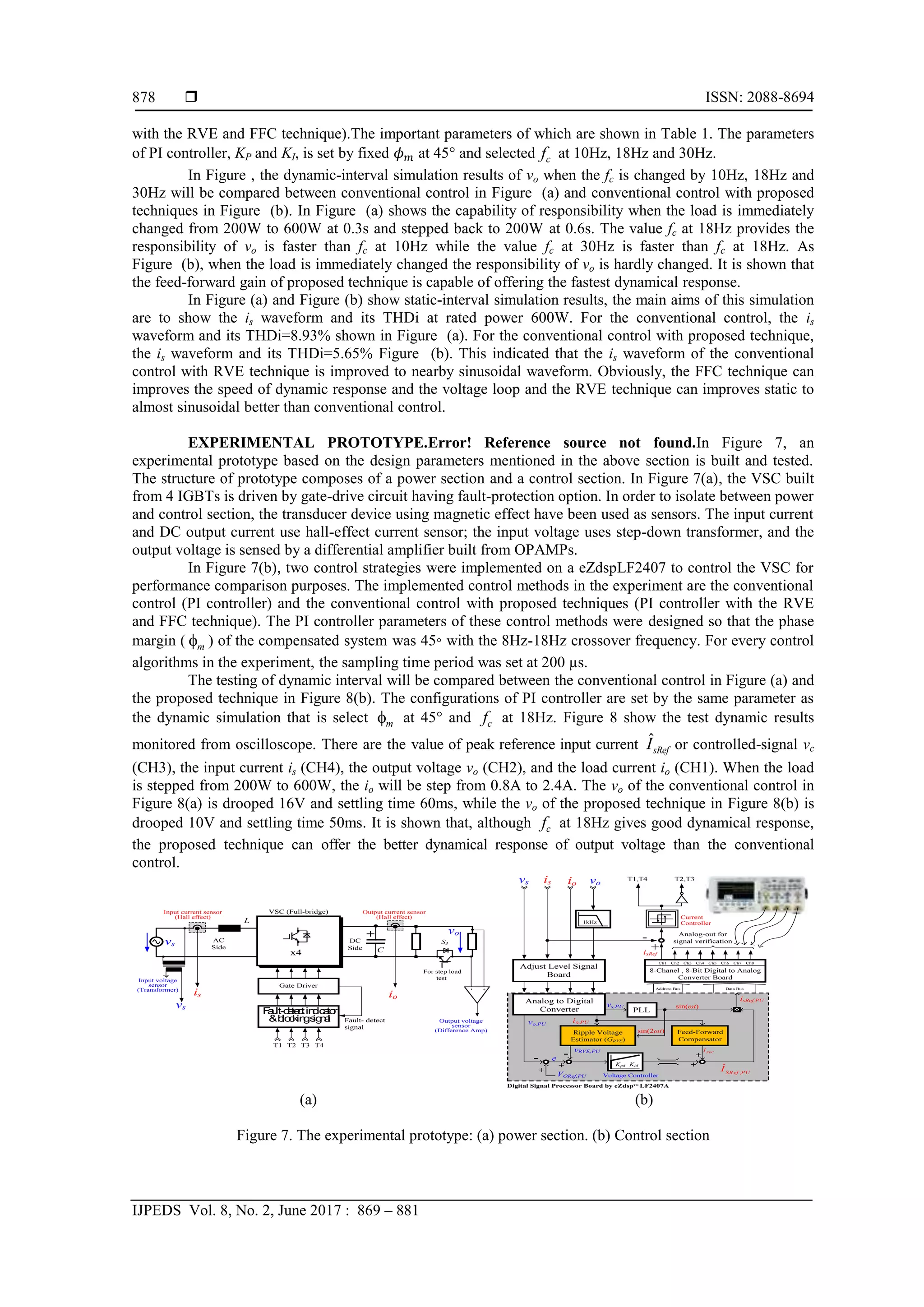
This document presents a study on reducing voltage ripple in the control loop of a full-bridge AC-DC voltage source converter (VSC) using a ripple voltage estimator (RVE) and feed-forward compensation (FFC) algorithms. These algorithms aim to improve the dynamical response and reduce the total harmonic distortion of the input current while maintaining a high power factor and overall efficiency. The proposed methods were validated through simulations and experiments, yielding promising results for power quality in electrical systems.
![International Journal of Power Electronics and Drive System (IJPEDS)
Vol. 8, No. 2, June 2017, pp. 869~881
ISSN: 2088-8694, DOI: 10.11591/ijpeds.v8i2.pp869-881 869
Journal homepage: http://iaesjournal.com/online/index.php/IJPEDS
Voltage Ripple Reduction in Voltage Loop of Voltage Source
Converter
Jedsada Jaroenkiattrai, Viboon Chunkag
Department of Electrical and Computer Engineering, King Mongkut’s University of Technology North Bangkok,
Thailand
Article Info ABSTRACT
Article history:
Received Feb 18, 2017
Revised Apr 18, 2017
Accepted May 2, 2017
In order to achieve a good dynamical response of a full-bridge AC-DC
voltage source converters (VSC). The bandwidth of PI controller must be
relatively wide. This leads to the voltage ripple produced in the control
signal, as known that its ripple frequency has twice of the line frequency and
cause the 3rd harmonic of an input current. A Ripple Voltage Estimator
(RVE) algorithm and Feed-Forward Compensation (FFC) algorithm are
proposed and added to the conventional control. The RVE algorithm
estimated the ripple signal to subtract it occurring in the voltage loop. As a
result, the 3rd harmonic of the input current can be reduced, and hence the
Total Harmonic Distortion of input current (THDi) are improved. In addition,
the FFC algorithm will offer a better dynamical response of output voltage.
The performance evaluation was conducted through the simulation and
experiment at 110Vrms/50Hz of the input voltage, with a 600 W load and
250 Vdc output voltage. The overall system performances are obtained as
follows: the power factor at the full load is higher 0.98, the harmonic
distortion at AC input power source of the converter is under control in
IEC61000-3-2 class A limit, and the overall efficiency is greater than 85%.
Keyword:
Feed-forward compensation
Full-bridge AC-DC converter
Power factor correction
Ripple voltage estimation
Voltage source converter
Copyright © 2017 Institute of Advanced Engineering and Science.
All rights reserved.
Corresponding Author:
Viboon Chunkag,
Department of Electrical and Computer Engineering,
King Mongkut’s University of Technology North Bangkok,
1518 Pracharat 1, Wongsawang, Bangsue, Bangkok 10800, Thailand.
Email: vck@kmutnb.ac.th
1. INTRODUCTION
Undoubtedly, using diode-bridge rectifier to assemble a single phase AC-DC Converters leads to
pollution in electrical system [1]. The line input current is non-sinusoidal and cause voltage distortion at the
Point of Common Coupling (PCC) which deviate from sinusoidal waveform. Consequently, high Total
Harmonic Distortion of current (THDi) and low power factor are occurred. A simple method [2] to reduce
those problems are to add a passive LC filter into AC input line voltage, but the input current is still far from
sinusoidal.
In order to compliance with necessary harmonic standards such as IEC 1000-3-2, an AC-DC Power
Factor Correction (PFC) converters using a Single Switch Topology (SST) such as Boost, Buck-Boost, CUK
and SEPIC has been introduced and widely popular [3]-[6]. These converters produce very low current
harmonic which injected into the line due to quasi-sinusoidal input current waveform. However a diode-
rectifier module is needded for installing to SST, and also the power can be flowed only one direction, from
AC side to DC side.
In [7]-[10], Voltage Source Converters (VSC) based on the full-bridge AC-DC converter circuit as
shown in Figure 1 are widely used in medium and high-power applications. Controlling of the VSC has the
same maner as the SST; nevertheless, it has advantage over SST in term of capability to control the power](https://image.slidesharecdn.com/366774-7258-1-pb-210607015915/75/Voltage-Ripple-Reduction-in-Voltage-Loop-of-Voltage-Source-Converter-1-2048.jpg)
![ ISSN: 2088-8694
IJPEDS Vol. 8, No. 2, June 2017 : 869 – 881
870
flow to be bi-directional. For this reason, they play an important role in renewale energy such as energy from
solar cell or wind turbine for injecting energy into utility grid of a AC power system.
The normal simple cascade control structure has been presented in [7]-[9], where outer loop is a
output voltage controller and inner loop is an input current controller. To achieve a good dynamical response
of the output voltage, the crossover frequency which is set in the PI controller must be relatively high. The
current loop forces the input current to track the reference current signal, which is obtained by multiplying a
sinusoidal signal template by a amplitude signal from feedback voltage in the voltage loop. Thus, if the
feedback voltage is a DC value, the reference input current signal will be sinusoidal. Then, the input current
can be forced to sinusoidal if the input current is perfectly controlled to track this reference signal. In
practical, a ripple signal at twice of the line frequency (100Hz for 50Hz line frequency) in the voltage error
signal is natural exist. Consequently the 3rd harmonic signal in the reference input current is occurred which
causes the distortion of reference input current and also the input line current. In order to reduce the ripple
voltage, an easy solution is to add a bulk-electrolytic capacitor at the output. However, this capacitor causes
to increase size and cost of the VSC, but cannot get rid of the double line frequency component in the voltage
control loop.
A standard design of voltage loop to reduce the THDi is placed a Low-Pass Filter (LPF) next after
an output voltage sensor. The LPF is tuned to offer cutoff frequency or bandwidth around 10Hz-20Hz, then
the ripple flowing from output voltage is attenuated. Although this design has improved the THDi of the
system, but the main disadvantage is lack of output voltage response. Conversely, if the LPF is loosened or
higher bandwidth, the responsibility will improve but the THDi will be increased. In some paper [10], the
voltage loop was controlled by the fuzzy controller, but the THDi was more 5%.
The power-balanced control algorithm or Feed-Forward Compensation (FFC) proposed by [4], the
main aim of them is to add the load information which is the disturbance before current loop. As a result the
output voltage dynamic response is improved, but the THDi will not be improved by this technique.
In [4] has been proposed the method for reducing the 3rd harmonic in PFC type CUK topology. The
output voltage is sampled to voltage loop. The sample period is at every zero crossing point of the input
voltage. So that only a DC value is collected to be multiply with the sinusoidal template. Therefore the
reference current signal will be perfectly sinusoidal. However the response of output voltage is still poor
because if the updating reference is occurred only 2 times in a line periode.
This paper will consider the situation in which the bandwidth of the LPF and the crossover
frequency of the PI controller is high value. The first part of paper presents an analysis of the conventional
cascade control VSC. Then propose the simple method to reduce a ripple voltage in voltage loop of the VSC
by using a Ripple Voltage Estimation (RVE) algorithm but offer better responsibility by using the FFC
algorithm. The output ripple is estimated by the RVE algorithm and subtract it from voltage error signal. The
result of this, the 3rd harmonic of the input current is reduced, and hence the THDi is improved. The concept
of the FFC technique is the same as the power balance control technique in feeding load information into
control system. These algorithms are implemented based on a microcontroller. Finally, the simulation and
experimental resuls are shown.
(a) (b) (c)
Figure 1. (a) The power circuit is a Voltage Source Converter (VSC) built from full-bridge AC-DC converter
and its cascade control. (b) The ripple in voltage loop which is the cause of distorted-reference input current
(c) Analysis the direction of output current.
vs C
LOAD
-
+
-
+
is L
T1 io
icap
T1,T4 T2,T3
VORef
Controller
Voltage
KI
Controller
Current
Kp
sin(ωt)
LPF
K2
PLL
vo
Current Control Loop
K1
K2
K2
K1
Voltage Control Loop
Power Section
ve
Sinusoidal template
ILoad
T3
T2
T4
vc
t
100Hz
0
f
t
0
Distored
2
3
C
Load
+
vo(Lt)
IODC
io(Lt) =IODC+io2(Lt)+io4(Lt)
io2(Lt)+io4(Lt)
isRef (t)
vcAC (t)
vc(t)=VCDC+vcAC (t)
VCDC
vo(t)=VODC+voAC (t)](https://image.slidesharecdn.com/366774-7258-1-pb-210607015915/75/Voltage-Ripple-Reduction-in-Voltage-Loop-of-Voltage-Source-Converter-2-2048.jpg)


![IJPEDS ISSN: 2088-8694
Voltage Ripple Reduction in Voltage Loop of Voltage Source Converter (Jedsada Jaroenkiattrai)
875
4. TRANSFER FUNCTION OF THE SYSTEM AND CONTROLLER DESIGNED
An analysis of the Single-phase AC-DC converter transfer function is presented under the continous
conductiontion mode of operation. The transfer function is used for designing voltage controller. As the
analysis for transfer function model, there are no AC component vo2(Lt) and vo4(Lt) at the output voltage.
Thus from (16), select only DC component and let k=0, the output current is (28).
2
1
0
ˆ
2
CDC S
ODC k
ODC
V KV
I
V
(28)
Applying perturbation in it to perform the small-signal approximation. Therefore, the output current can be
expressed as
ODC ODC
ODC CDC ODC
CDC ODC
I I
I V V
V V
(29)
Since the voltage source converter transfer function (GVSC) and Disturbance transfer function (GD) can be
define as
2
1
ˆ
2
ODC S
VSC
CDC ODC
I V K
G
V V
and
2
1
2
ˆ 1
2( )
ODC S CDC
D
ODC Load
ODC
I V V K
G
V R
V
(30)
The notation used in this section to describe the quantities. From (29), the variables with the sign ‘˜’ are the
small signal values.The output impedance (GZ) can be define as
( )
1
ODC Load
Z
Load
ODC
V R
G s
R Cs
I
(31)
Since the controller in the current loop, hysteresis controller, is selected, the dynamic response of
input current is fast enough to track the reference value of the input current. Thus, the transfer function of
closed current loop can be approximated as ˆS
I . In order to design voltage controller for the next issue, then
the closed-loop system block diagram is obtained from (29), (30) and (31) shown in Figure 3(a). To avoid
line current distortion in the VSC, the system crossover frequency in the voltage loop should be between
10-20 Hz (50 Hz line frequency) [4]. According to the low crossover frequency, the transient response of the
PFC circuit is limited especially under the step-load condition. In the case of voltage and current are been the
per-unit system, the plant transfer function (the voltage controller is not included) can be written
1
.
ˆ
( ) ( ) ( )
P LPF S VSC Z
P U Current
Low
Gain Control
Pass
Loop
Filter
G s K G s I G G s
(32)
Where ˆS
I is peak input current and ˆS
V is peak input voltage. The Open-Loop Transfer Function (OLTF) can
be written as
( ) ( ) ( )
CV P
OLTF s G s G s
(33)
Where the GCV(s) is voltage controller, PI controller, can be obtained as
( ) I
CV P
K
G s K
s
(34)
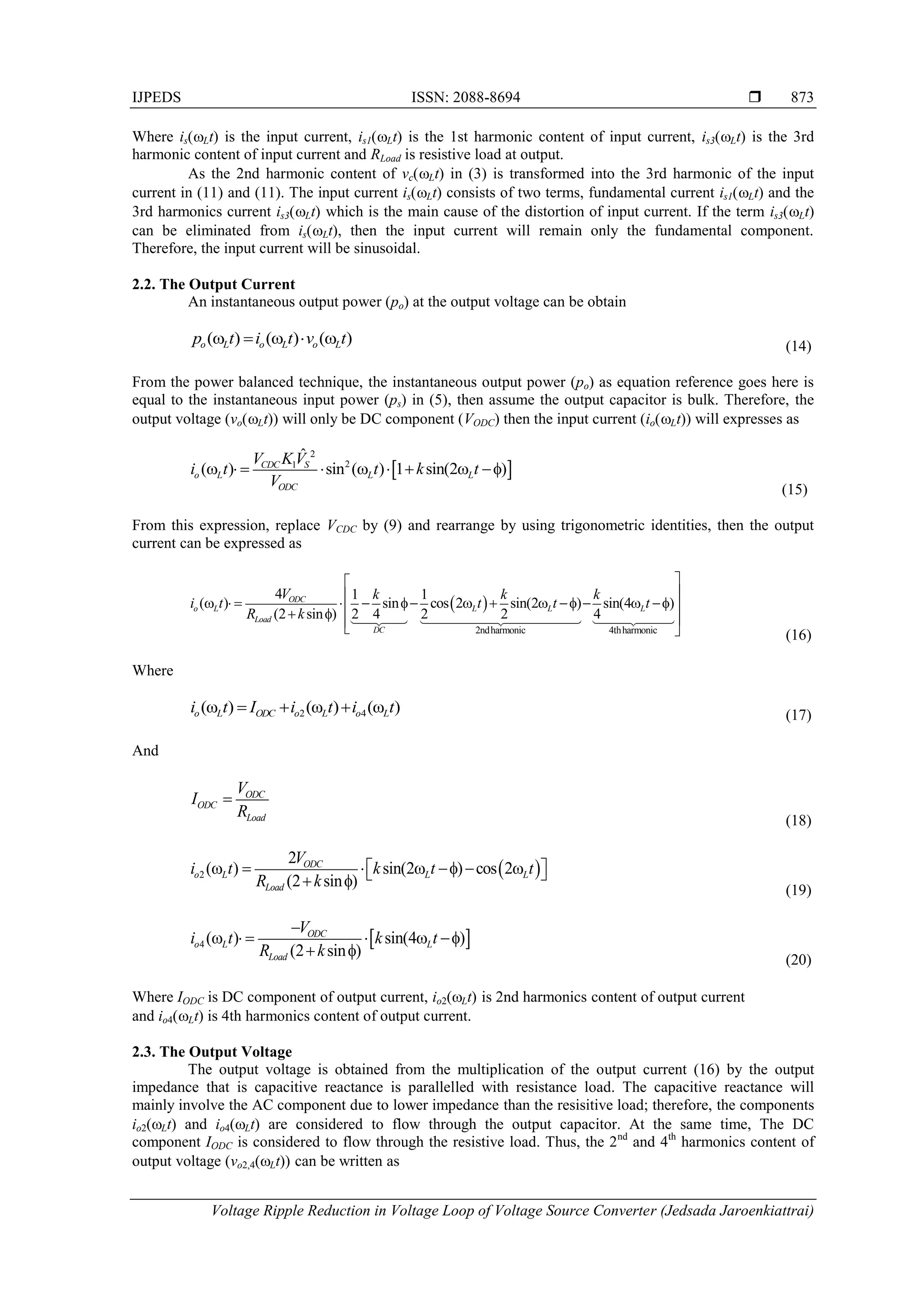
Where KP is proportional gain and KI is integral gain. The procedure for designing GCV(s), first, select the
phase margin m
f and crossover frequency c
f by 2
c c
f
. Then calculate the by substituting them into
Equation (35). Finally, KP and KI will be obtained by (36).](https://image.slidesharecdn.com/366774-7258-1-pb-210607015915/75/Voltage-Ripple-Reduction-in-Voltage-Loop-of-Voltage-Source-Converter-7-2048.jpg)
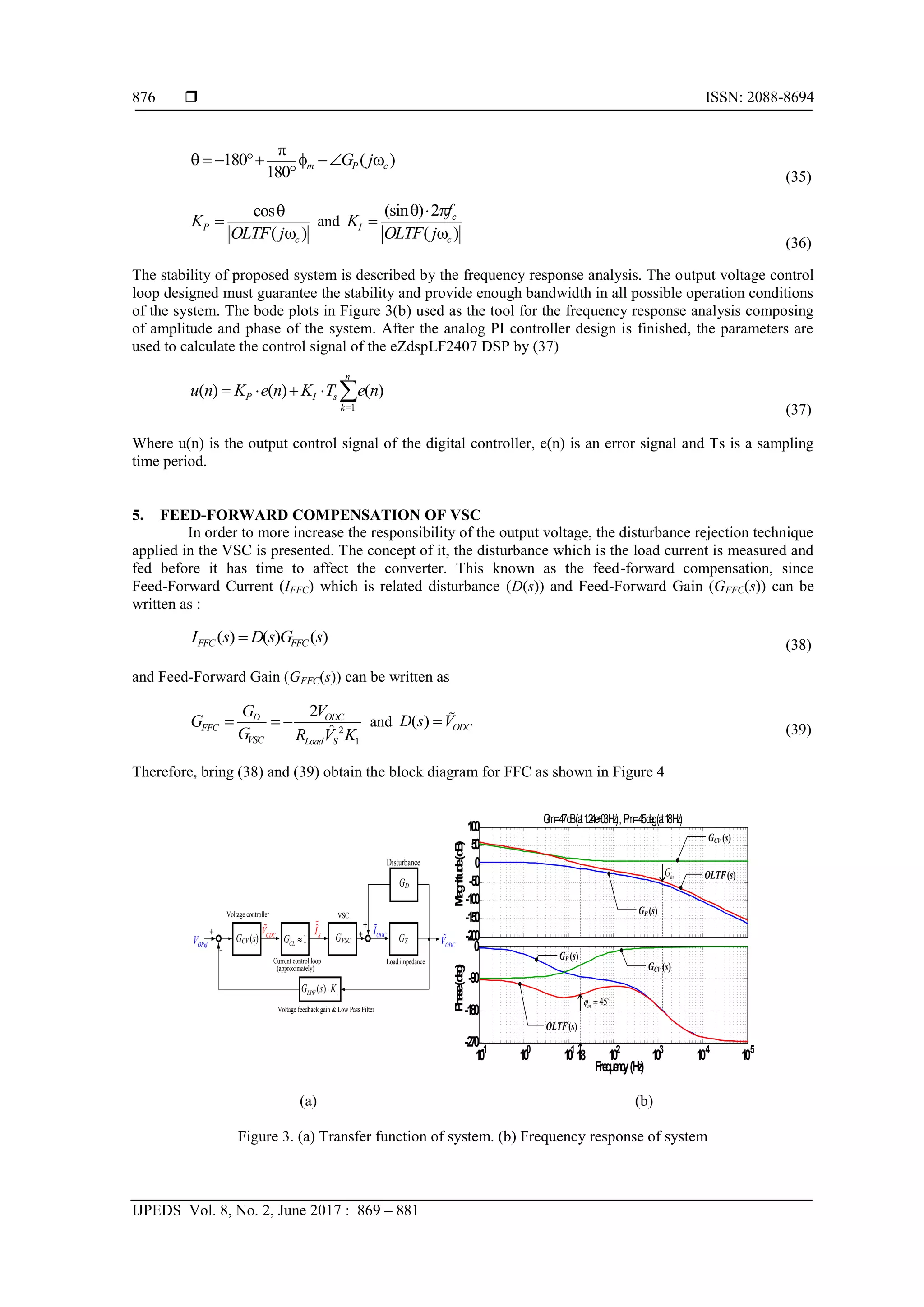
![IJPEDS ISSN: 2088-8694
Voltage Ripple Reduction in Voltage Loop of Voltage Source Converter (Jedsada Jaroenkiattrai)
877
Figure 4. The proposed technique consists of the RVE and FFC
Table 1. Parameters of the proposed system
Parameters Values
VS, fLine 110 Vrms, 50 Hz
VORef 250 Vdc
L,C 15 mH, 560 µF
PoMax 600 W
(a) (b)
Figure 5. The dynamic-interval simulation results of vo when the fc is changed by 10Hz, 18Hz and 30Hz:
(a) The conventional control. (b) The conventional control with proposed technique.
(a) (b)
Figure 6. The input current and its total harmonic distortion (THDi) at 600W of the static-simulation results:
(a) The conventional control. (b) the conventional control with proposed technique
6. CIRCUIT SIMULATIONS
In this section, the simulation of the VSC is discussed. The configuration of which is simulated by
SIMULINK program. The purpose of this simulation is to test the parameter of controllers, verify the control
algorithms, and study the static and the dynamic of the proposed system. The simulation methods are the
conventional control (PI controller) and the conventional control with proposed techniques (PI controller
-
+
VORef
Voltage Controller
KP
ve
iLoad
K2
K2
2
1
2
ˆ
ORef
FFC
S
V
G
V K
-
+
-
+
From DC Voltage LPF
sinωLt
Sin(2ωLt)
Current
control loop
R
ip
p
leV
o
lta
g
eE
s
tim
a
to
r
F
e
e
d
-F
o
rw
a
rdC
o
m
p
e
n
s
a
tio
n
1
2
2
RVE
L
K
G
CK
GFFC
GRVE
FFC
I
vc
voRVE
KI
0.25 0.3 0.35 0.4 0.45 0.5 0.55 0.6 0.65 0.7 0.75
210
220
230
240
250
260
270
280
290
@ fc=30Hz
@ fc=18Hz
@ fc=10Hz
Output
Voltage
(
)
:
[V]
o
V
Time ( ) : [Sec]
t
@ fc=10Hz
@ fc=30Hz
@ fc=18Hz
Step load
200W to 600W
Step load 600W
to 200W
Output voltage fixed but different values of
m c
f
f
2
2
3
V
2
3
3
V
2
3
9
V
2
5
9
V
2
6
8
V
2
8
0
V
210
220
230
240
250
260
270
280
290
0.25 0.3 0.35 0.4 0.45 0.5 0.55 0.6 0.65 0.7 0.75
Time ( ) : [Sec]
t
Step load
200W to 600W
Step load 600W
to 200W
Output
Voltage
(
)
:
[V]
o
V
Output voltage fixed but different values of
m c
f
f
-PI Controller+FFC
-Fixed 45
m
f
-PI Controller
-Fixed 45
m
f
0.5 0.502 0.504 0.506 0.508 0.51 0.512 0.514 0.516 0.518 0.52
-15
-10
-5
0
5
10
15
0.5 0.502 0.504 0.506 0.508 0.51 0.512 0.514 0.516 0.518 0.52
-15
-10
-5
0
5
10
15
0 100 200 300 400 500 600 700 800 900 1000
0
0.2
0.4
0.6
Frequency (Hz)
Fundamental (50Hz) = 7.973 , THD= 8.93%
Mag
(%
of
Fundamental)
0 100 200 300 400 500 600 700 800 900 1000
0
0.1
0.2
0.3
0.4
0.5
Frequency (Hz)
Fundamental (50Hz) = 7.961 , THD= 5.65%
Mag
(%
of
Fundamental)](https://image.slidesharecdn.com/366774-7258-1-pb-210607015915/75/Voltage-Ripple-Reduction-in-Voltage-Loop-of-Voltage-Source-Converter-9-2048.jpg)
![IJPEDS ISSN: 2088-8694
Voltage Ripple Reduction in Voltage Loop of Voltage Source Converter (Jedsada Jaroenkiattrai)
881
REFERENCES
[1] O. Garcia, J. A. Cobos, R. Prieto, P. Alou, J. Uceda. Single phase power factor correction: a survey. IEEE
Transactions on Power Electronics. 2003; 18: 749-755.
[2] M. M. Jovanovic, D. E. Crow. Merits and limitations of full-bridge rectifier with LC filter in meeting IEC 1000-3-2
harmonic-limit specifications. IEEE Transactions on Industry Applications. 1997; 33: 551-557.
[3] U. Kamnarn, V. Chunkag. Analysis and Design of a Modular Three-Phase AC-to-DC Converter Using CUK
Rectifier Module With Nearly Unity Power Factor and Fast Dynamic Response. IEEE Transactions on Power
Electronics. 2009; 24: 2000-2012.
[4] P. Wisutmetheekorn, V. Chunkag. Digital Control of an AC/DC Converter using the Power Balance Control
Technique with Average Output Voltage Measurement. Journal of Power Electronics. 2012; 12(1): 88-97.
[5] Y. Cho, U. Konkuk. A Low Cost SingleSwitch Bridgeless Boost PFC Converter. International Journal of Power
Electronics and Drive Systems (IJPEDS). 2014; 4: 256-264.
[6] Md. Ismail Hossain, Mohammad Jahangir Alam. Single stage single phase active power factor corrected Ĉuk
Topology Based AC-DC Converter. International Journal of Power Electronics and Drive Systems (IJPEDS). 2014;
4(2): 156-164.
[7] O. Stihi, B. T. Ooi. A single-phase controlled-current PWM rectifier. IEEE Transactions on Power Electronics.
1988; 3: 453-459.
[8] S. Somkun, P. Sehakul, V. Chunkag. Novel control technique of single-phase PWM rectifier by compensating output
ripple voltage. IEEE International Conference on Industrial Technology. 2005: 969-974.
[9] B. K V, B. J. Rabi. A Novel Power Factor Correction Rectifier for Enhancing Power Quality. International Journal
of Power Electronics and Drive Systems (IJPEDS), 2015; 6(4): 772-780.
[10] D. Lenine, C. Sai Babu, G. Shankaraiah. Performance Evaluation of Fuzzy and PI Controller for Boost Converter
with Active PFC. International Journal of Power Electronics and Drive Systems (IJPEDS). 2012; 2(4): 445-453.](https://image.slidesharecdn.com/366774-7258-1-pb-210607015915/75/Voltage-Ripple-Reduction-in-Voltage-Loop-of-Voltage-Source-Converter-13-2048.jpg)


![[IJET V2I2P30] Authors: AnkurGheewala, Jay Chanawala,Nikhil Jadav,Modi Rishit...](https://cdn.slidesharecdn.com/ss_thumbnails/ijet-v2i2p30-160609050010-thumbnail.jpg?width=640&height=640&fit=bounds)


![Final presentation [Autosaved].pptxFinal presentation [Autosaved].pptxFinal p...](https://cdn.slidesharecdn.com/ss_thumbnails/finalpresentationautosaved-250527075000-e9e51fee-thumbnail.jpg?width=640&height=640&fit=bounds)


![[9] a systematic parameter tuning of pi current controller for lcl type activ...](https://cdn.slidesharecdn.com/ss_thumbnails/9asystematicparametertuningofpicurrentcontrollerforlcl-typeactiverectifiersunderunbalancedgridvoltag-200723180821-thumbnail.jpg?width=640&height=640&fit=bounds)