Downloaded 57 times
![Innovative Systems Design and Engineering www.iiste.org
ISSN 2222-1727 (Paper) ISSN 2222-2871 (Online)
Vol 3, No 2, 2012
Power Flow Control/Limiting Short Circuit Current Using
TCSC
Gannavarapu Akhilesh1* D.Raju2
1. ACTS, JNTU-H, PO box 500035, Hyderabad, Andhra Pradesh, India
2. M.Tech (NIT Nagpur), Hyderabad, Andhra Pradesh, India.
*E-mail of the corresponding author: akkigannavarapu@gmail.com
Abstract
This paper presents the various advantages of Thyristor Controller Series Capacitor (TCSC), both as a Power
Flow Controller, as well as a Short Circuit limiter during faults. The results have been derived and verified
from the software PSCAD, and the graphs and calculations are included in the paper. The results and
information included in the paper are sufficiently accurate.
Keywords: Modelling, power system dynamic stability.
1. Introduction
Thyristor Controlled Series Capacitor (TCSC) is a series FACTS device which allows rapid band continuous
changes of the transmission line impedance. It has great application potential in accurately regulating the
power flow on a transmission line, damping inter-area power oscillations, mitigating sub synchronous
resonance (SSR) and improving transient stability.
The characteristics of a TCSC at steady-state and very low frequencies can be studied using fundamental
frequency analytical models [1], [2]. These particular models recognize the importance of having different
approach from SVC modeling (assuming only line current as a constant) which, although more demanding on
the derivation, gives the most accurate TCSC model.
The fundamental frequency models cannot be used in wider frequency range since they only give the
relationship among fundamental components of variables when at steady-state.
Conventionally, the electromechanical transient programs like EMTP or PSCAD/EMTDC are used for
TCSC transient stability analysis. These simulation tools are accurate but they employ trial and error type
studies only, implying use of a large number of repetitive simulation runs for varying parameters in the case
of complex analysis or design tasks. On the other hand, the application of dynamic systems analysis
techniques or modern control design theories would bring benefits like shorter design time, optimization of
resources and development of new improved designs. In particular, the eigenvalue and frequency domain
analysis are widely recognized tools and they would prove invaluable for system designers and operators.
These techniques however always necessitate a suitable and accurate dynamic system model.
13](https://image.slidesharecdn.com/powerflowcontrollimitingshortcircuitcurrentusingtcsc-120126065549-phpapp02/85/Power-flow-control-limiting-short-circuit-current-using-tcsc-1-320.jpg)
![Innovative Systems Design and Engineering www.iiste.org
ISSN 2222-1727 (Paper) ISSN 2222-2871 (Online)
Vol 3, No 2, 2012
There have been a number of attempts to derive an accurate analytical model of a TCSC that can be employed
in system stability studies and controller design [3]–[6]. The model presented in [3] uses a special form of
discretization, applying Poincare mapping, for the particular Kayenta TCSC installation. The model
derivation for a different system will be similarly tedious and the final model form is not convenient for the
application of standard stability studies and controller design theories especially not for larger systems. A
similar final model form is derived in [4], and the model derivation is improved since direct discretization of
the linear system model is used, however, it suffers other shortcomings as the model in [3]. The modeling
principle reported in [5] avoids discretization and stresses the need for assuming only line current as an ideal
sine, however, it employs rotating vectors that might be difficult to use with stability studies, and only
considers the open loop configuration. The model in [5] is also oversimplified because of the use of
equivalent reactance and equivalent capacitance that might be deficient when used in wider frequency range.
Most of these re- ported models are therefore concerned with a particular system or particular type of study,
use overly simplified approach and do not include control elements or phase-locked loops (PLLs). In this
study, we attempt to derive a suitable linear continuous TCSC model in state-space form. The model should
have reasonable accuracy for the dynamic studies in the sub synchronous range and it should incorporate
common control elements including PLL. To enable flexibility of the model use with different ac systems, the
model structure adopts subsystem units interlinked in similar manner as with SVC modeling [6].
We also seek to offer complete closed-loop model verification in the time and frequency domains.
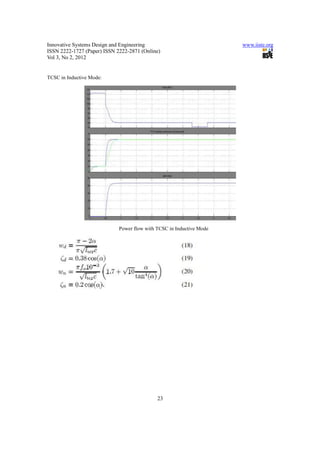
1.1 Test System
The test system for the study is a long transmission system compensated by a TCSC and connected to a firm
voltage source on each side. Fig. 1 shows a single line diagram of the test system where the transmission line
is represented by a lumped resistance and inductance in accordance with the approach for sub-synchronous
resonance studies [7]. Each phase of the TCSC is composed of a fixed capacitor in parallel with a
thyristor-controlled reactor (TCR). The TCSC is controlled by varying the phase delay of the thyristor firing
pulses synchronized through a PLL to the line current waveform.
14](https://image.slidesharecdn.com/powerflowcontrollimitingshortcircuitcurrentusingtcsc-120126065549-phpapp02/85/Power-flow-control-limiting-short-circuit-current-using-tcsc-2-320.jpg)
![Innovative Systems Design and Engineering www.iiste.org
ISSN 2222-1727 (Paper) ISSN 2222-2871 (Online)
Vol 3, No 2, 2012
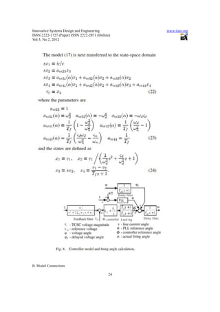
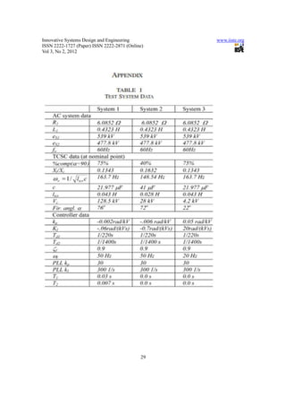
Three different test systems are used in order to verify the model accuracy with different system parameter
and different operating points:
• System 1—75% compensation, capacitive mode;
• System 2—40% compensation, capacitive mode;
• System 3—75% compensation, inductive mode.
The test system parameters are practically selected according to the recommendations in [8]
(regarding and natural resonance) and the test system data are given in the Appendix.
1.2 Fundamental Frequency Model
15](https://image.slidesharecdn.com/powerflowcontrollimitingshortcircuitcurrentusingtcsc-120126065549-phpapp02/85/Power-flow-control-limiting-short-circuit-current-using-tcsc-3-320.jpg)
![Innovative Systems Design and Engineering www.iiste.org
ISSN 2222-1727 (Paper) ISSN 2222-2871 (Online)
Vol 3, No 2, 2012
The fundamental frequency model of a TCSC is derived first to enable initialization of the steady-state
parameters. The voltage across the TCSC capacitor comprises an uncontrolled and a controlled component
[8], and it is presumed that the line current is constant over one fundamental cycle in accordance with [1], [2],
[5]. The uncontrolled component is a sine wave (unaffected by thyristor switching) and it is also constant
over a fundamental cycle since it is directly related to the amplitude of the prevailing line current. The
controlled component is a nonlinear variable that depends on circuit variables and on the TCR firing
angle.
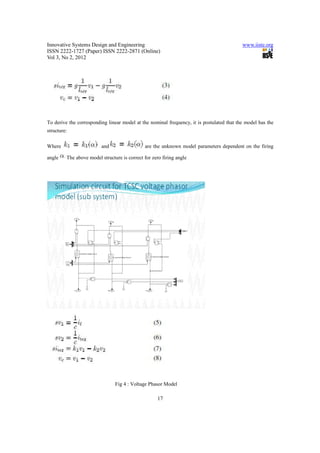
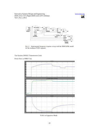
In this study, the controlled component is represented as a nonlinear function of the uncontrolled component
and firing angle, as shown in Fig. 2.With this approach, captures the nonlinear phenomena caused by
thyristor switching influence and all internal interactions with capacitor voltage assuming
only that the line current and are linear. We seek in our work to study dynamics of in a wider frequency
range and also to offer a simplified representation for fundamental frequency studies. The fundamental
components of reactor current and the voltages and are selected as state variables and the non- linear
state-space model is presented as
Simulation Circuit for TCSC (500 KV System)
16](https://image.slidesharecdn.com/powerflowcontrollimitingshortcircuitcurrentusingtcsc-120126065549-phpapp02/85/Power-flow-control-limiting-short-circuit-current-using-tcsc-4-320.jpg)
![Innovative Systems Design and Engineering www.iiste.org
ISSN 2222-1727 (Paper) ISSN 2222-2871 (Online)
Vol 3, No 2, 2012
( , i.e., full conduction with measured from the voltage crest) and we presume the same
model structure but different parameter values for .
Considering the two components of the thyristor current on the right side of (7) we note that produces
the current that is driven by a constant voltage (over one fundamental cycle) in accordance to the earlier
assumption. As a result, the configuration is similar to the shunt connection of TRC in a SVC, and the
constant can be calculated using the approach of equivalent reactance for the TCR current in a SVC
[6], [8]
In order to determine the constant , we represent (6)–(7) as
a transfer function in the following form:
Observing (10), it is seen that is the resonant frequency of an undamped second order system. The
proposed expression for this frequency is given below in (12) and it is determined using the experimental
frequency response of the model for the nonlinear TCSC segment as presented later in Section 1.3.
18](https://image.slidesharecdn.com/powerflowcontrollimitingshortcircuitcurrentusingtcsc-120126065549-phpapp02/85/Power-flow-control-limiting-short-circuit-current-using-tcsc-6-320.jpg)
![Innovative Systems Design and Engineering www.iiste.org
ISSN 2222-1727 (Paper) ISSN 2222-2871 (Online)
Vol 3, No 2, 2012
Fig 5: Simulation Circuit for TCSC.
TCSC gain at fundamental frequency is derived
TCSC fundamental frequency impedance is
Where
And is defined in (12).
Compared with the fundamental frequency TCSC model in [1], [2], the derived model (13) is considerably
simpler, yet it will be shown that the accuracy is very similar.
19](https://image.slidesharecdn.com/powerflowcontrollimitingshortcircuitcurrentusingtcsc-120126065549-phpapp02/85/Power-flow-control-limiting-short-circuit-current-using-tcsc-7-320.jpg)
![Innovative Systems Design and Engineering www.iiste.org
ISSN 2222-1727 (Paper) ISSN 2222-2871 (Online)
Vol 3, No 2, 2012
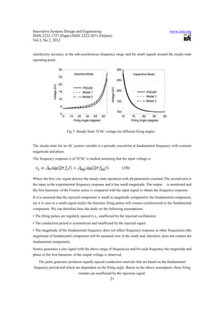
The above model is tested against PSCAD in the following way. The system is operated in open loop, i.e.,
with a fixed reference thyristor firing angle, in the configuration of Fig. 1. The value of the reference thyristor
angle is changed in interval and for each angle the value of the TCSC voltage
is observed. Since all other parameters are constant, the TCSC voltage is directly proportional to the TCSC
impedance and this is an effective way to obtain accurate information on the fundamental TCSC impedance.
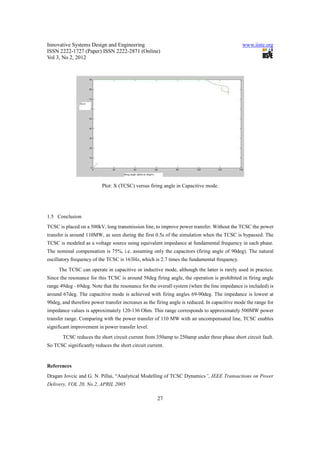
Fig. 3 shows the steady-state TCSC voltage against the range of firing angle values, where the above linear
model results are shown as model 2 and also the results from researchers [1], [2] as model 1. It is seen that the
proposed model shows good accuracy across the entire firing angle range and especially the results are very
close to those from [1], [2]. In fact the above model differs negligibly from the model [1], [2], except in the
less used low firing angles in range where the difference is still below 5%. It is also
evident that the two analytical models show small but consistent discrepancy against PSCAD/EMTDC, and
despite all simplifications in PSCAD it was not possible to obtain better matching.
Fig 6: TCSC Power measurement.
1.3 Small-Signal Dynamic Analytical Model
A. TCSC Model
The transfer function in (10) is accurate only at fundamental frequency and it cannot be used for wider
frequency studies. The goal of the dynamic modeling is to derive a dynamic expression for model of
20](https://image.slidesharecdn.com/powerflowcontrollimitingshortcircuitcurrentusingtcsc-120126065549-phpapp02/85/Power-flow-control-limiting-short-circuit-current-using-tcsc-8-320.jpg)
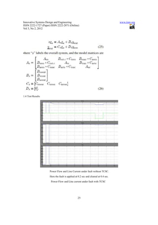
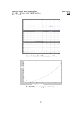

1. The document presents a model and analysis of a Thyristor Controlled Series Capacitor (TCSC) used in power flow control on a 500kV transmission line. 2. The TCSC model is developed using PSCAD software and analytical methods. Test results show the TCSC is able to increase power transfer on the line from 110MW to over 500MW by varying the TCSC reactance through adjustments to the firing angle. 3. Additionally, the TCSC is shown to reduce short circuit current during a fault on the line from 350A to 250A, demonstrating its ability to limit fault current.