Downloaded 488 times

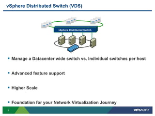
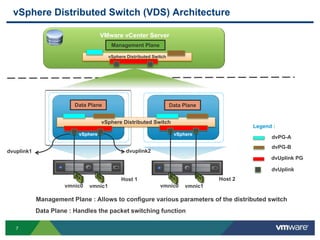
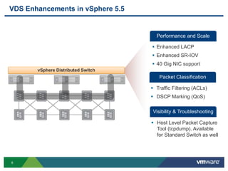

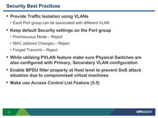
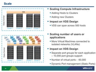
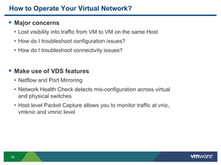


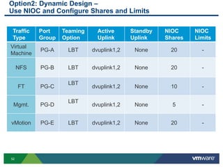
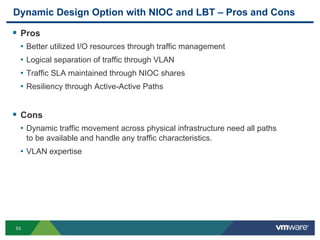

The document outlines the design and best practices for using VMware's vSphere Distributed Switch (VDS), highlighting its new capabilities and enhancements in version 5.5. It covers various aspects such as deployment strategies, infrastructure design goals, security measures, performance issues, and the importance of using features like Network I/O Control (NIOC) and Load Based Teaming (LBT). Additionally, it provides recommendations for ensuring reliable, secure, and scalable virtual network architecture.


![[AKIBA.AWS] AWS Elemental MediaConvertから学ぶコーデック入門](https://cdn.slidesharecdn.com/ss_thumbnails/akibaaws4up-180130002606-thumbnail.jpg?width=640&height=640&fit=bounds)


![Wp br v7_a_vmware_architects_favorite_features[1]](https://cdn.slidesharecdn.com/ss_thumbnails/wpbrv7avmwarearchitectsfavoritefeatures1-131003071359-phpapp01-thumbnail.jpg?width=640&height=640&fit=bounds)