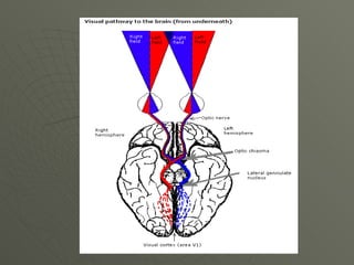
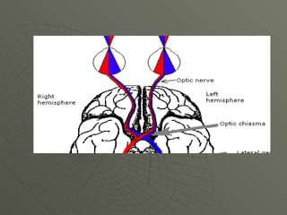
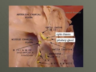
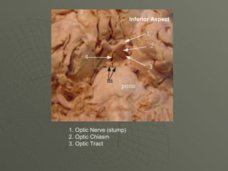
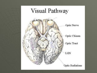
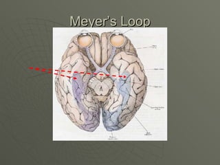
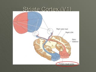
1. The document describes the visual pathway from the eye to the visual cortex. It begins with the retina and optic nerve, followed by the optic chiasm, optic tract, lateral geniculate nucleus, optic radiations including Meyer's loop, and primary visual cortex (V1).
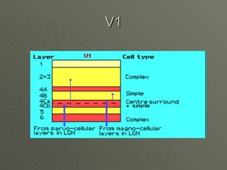
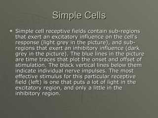
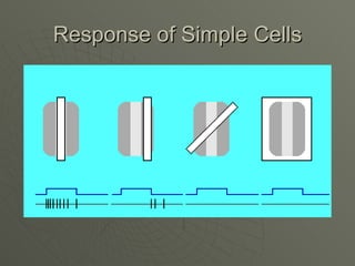
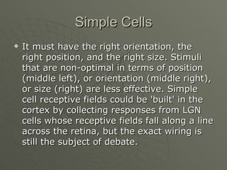
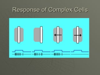
2. V1 contains two main types of cells - simple cells that respond to oriented edges in specific positions, and complex cells that are position invariant but retain orientation tuning.
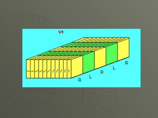
3. Cells in V1 are organized into orientation columns where neurons within a column prefer the same stimulus orientation.
The optic nerve (CN II) is the second cranial nerve, responsible for transmitting the special sensory information for vision.
It is developed from the optic vesicle, an outpocketing of the forebrain. The optic nerve can therefore be considered part of the central nervous system, and examination of the nerve enables an assessment of intracranial health.
Due to its unique anatomical relation to the brain, the optic nerve is surrounded by the cranial meninges (not by epi-, peri- and endoneurium like most other nerves).
The visual pathway/visual system is the part of central nervous system which gives organisms the ability to process visual detail , as well as enabling the formation of several non-image photo response functions.
It detects interprets information from visible light to build a representation of the surrounding environment .
The visual system carries out a number of complex tasks , including the reception of light and the formation of monocular representations; the buildup of a nuclear binocular perception from a pair of two dimensional projections ; the identification and categorization of visual objects ; assessing distances to and between objects and guiding body movements in relation to the objects seen.
It is also called as Visual system & is a part of Central nervous system.
Anatomy & Physiology of Visual pathway.
The References are given in the presentation itself.
Accelerate your Kubernetes clusters with Varnish CachingThijs Feryn
A presentation about the usage and availability of Varnish on Kubernetes. This talk explores the capabilities of Varnish caching and shows how to use the Varnish Helm chart to deploy it to Kubernetes.
This presentation was delivered at K8SUG Singapore. See https://feryn.eu/presentations/accelerate-your-kubernetes-clusters-with-varnish-caching-k8sug-singapore-28-2024 for more details.
Key Trends Shaping the Future of Infrastructure.pdfCheryl Hung
Keynote at DIGIT West Expo, Glasgow on 29 May 2024.
Cheryl Hung, ochery.com
Sr Director, Infrastructure Ecosystem, Arm.
The key trends across hardware, cloud and open-source; exploring how these areas are likely to mature and develop over the short and long-term, and then considering how organisations can position themselves to adapt and thrive.
Dev Dives: Train smarter, not harder – active learning and UiPath LLMs for do...UiPathCommunity
💥 Speed, accuracy, and scaling – discover the superpowers of GenAI in action with UiPath Document Understanding and Communications Mining™:
See how to accelerate model training and optimize model performance with active learning
Learn about the latest enhancements to out-of-the-box document processing – with little to no training required
Get an exclusive demo of the new family of UiPath LLMs – GenAI models specialized for processing different types of documents and messages
This is a hands-on session specifically designed for automation developers and AI enthusiasts seeking to enhance their knowledge in leveraging the latest intelligent document processing capabilities offered by UiPath.
Speakers:
👨🏫 Andras Palfi, Senior Product Manager, UiPath
👩🏫 Lenka Dulovicova, Product Program Manager, UiPath
UiPath Test Automation using UiPath Test Suite series, part 4DianaGray10
Welcome to UiPath Test Automation using UiPath Test Suite series part 4. In this session, we will cover Test Manager overview along with SAP heatmap.
The UiPath Test Manager overview with SAP heatmap webinar offers a concise yet comprehensive exploration of the role of a Test Manager within SAP environments, coupled with the utilization of heatmaps for effective testing strategies.
Participants will gain insights into the responsibilities, challenges, and best practices associated with test management in SAP projects. Additionally, the webinar delves into the significance of heatmaps as a visual aid for identifying testing priorities, areas of risk, and resource allocation within SAP landscapes. Through this session, attendees can expect to enhance their understanding of test management principles while learning practical approaches to optimize testing processes in SAP environments using heatmap visualization techniques
What will you get from this session?
1. Insights into SAP testing best practices
2. Heatmap utilization for testing
3. Optimization of testing processes
4. Demo
Topics covered:
Execution from the test manager
Orchestrator execution result
Defect reporting
SAP heatmap example with demo
Speaker:
Deepak Rai, Automation Practice Lead, Boundaryless Group and UiPath MVP
GraphRAG is All You need? LLM & Knowledge GraphGuy Korland
Guy Korland, CEO and Co-founder of FalkorDB, will review two articles on the integration of language models with knowledge graphs.
1. Unifying Large Language Models and Knowledge Graphs: A Roadmap.
https://arxiv.org/abs/2306.08302
2. Microsoft Research's GraphRAG paper and a review paper on various uses of knowledge graphs:
https://www.microsoft.com/en-us/research/blog/graphrag-unlocking-llm-discovery-on-narrative-private-data/
Encryption in Microsoft 365 - ExpertsLive Netherlands 2024Albert Hoitingh
In this session I delve into the encryption technology used in Microsoft 365 and Microsoft Purview. Including the concepts of Customer Key and Double Key Encryption.
GDG Cloud Southlake #33: Boule & Rebala: Effective AppSec in SDLC using Deplo...James Anderson
Effective Application Security in Software Delivery lifecycle using Deployment Firewall and DBOM
The modern software delivery process (or the CI/CD process) includes many tools, distributed teams, open-source code, and cloud platforms. Constant focus on speed to release software to market, along with the traditional slow and manual security checks has caused gaps in continuous security as an important piece in the software supply chain. Today organizations feel more susceptible to external and internal cyber threats due to the vast attack surface in their applications supply chain and the lack of end-to-end governance and risk management.
The software team must secure its software delivery process to avoid vulnerability and security breaches. This needs to be achieved with existing tool chains and without extensive rework of the delivery processes. This talk will present strategies and techniques for providing visibility into the true risk of the existing vulnerabilities, preventing the introduction of security issues in the software, resolving vulnerabilities in production environments quickly, and capturing the deployment bill of materials (DBOM).
Speakers:
Bob Boule
Robert Boule is a technology enthusiast with PASSION for technology and making things work along with a knack for helping others understand how things work. He comes with around 20 years of solution engineering experience in application security, software continuous delivery, and SaaS platforms. He is known for his dynamic presentations in CI/CD and application security integrated in software delivery lifecycle.
Gopinath Rebala
Gopinath Rebala is the CTO of OpsMx, where he has overall responsibility for the machine learning and data processing architectures for Secure Software Delivery. Gopi also has a strong connection with our customers, leading design and architecture for strategic implementations. Gopi is a frequent speaker and well-known leader in continuous delivery and integrating security into software delivery.
Neuro-symbolic is not enough, we need neuro-*semantic*Frank van Harmelen
Neuro-symbolic (NeSy) AI is on the rise. However, simply machine learning on just any symbolic structure is not sufficient to really harvest the gains of NeSy. These will only be gained when the symbolic structures have an actual semantics. I give an operational definition of semantics as “predictable inference”.
All of this illustrated with link prediction over knowledge graphs, but the argument is general.
Elevating Tactical DDD Patterns Through Object CalisthenicsDorra BARTAGUIZ
After immersing yourself in the blue book and its red counterpart, attending DDD-focused conferences, and applying tactical patterns, you're left with a crucial question: How do I ensure my design is effective? Tactical patterns within Domain-Driven Design (DDD) serve as guiding principles for creating clear and manageable domain models. However, achieving success with these patterns requires additional guidance. Interestingly, we've observed that a set of constraints initially designed for training purposes remarkably aligns with effective pattern implementation, offering a more ‘mechanical’ approach. Let's explore together how Object Calisthenics can elevate the design of your tactical DDD patterns, offering concrete help for those venturing into DDD for the first time!
Kubernetes & AI - Beauty and the Beast !?! @KCD Istanbul 2024Tobias Schneck
As AI technology is pushing into IT I was wondering myself, as an “infrastructure container kubernetes guy”, how get this fancy AI technology get managed from an infrastructure operational view? Is it possible to apply our lovely cloud native principals as well? What benefit’s both technologies could bring to each other?
Let me take this questions and provide you a short journey through existing deployment models and use cases for AI software. On practical examples, we discuss what cloud/on-premise strategy we may need for applying it to our own infrastructure to get it to work from an enterprise perspective. I want to give an overview about infrastructure requirements and technologies, what could be beneficial or limiting your AI use cases in an enterprise environment. An interactive Demo will give you some insides, what approaches I got already working for real.
2. Visual Pathway
“Focus on the Eye”
• Concerned about
Cornea
Lens
Retina
There is more to vision than meets
the eye
3.
4. Retinal Fields vs. Visual Fields
What’s the difference
• Retinal Field – describes the area that includes
neural fibers of the retina that are receiving
light from some object
• Visual Field – describes the area in space
where the object lies
They are the reversal of one another
• The nasal retinal field receives light from the
temporal visual field
• The temporal retinal field receives light from
the nasal visual field
5. Temporal Temporal
Visual field Visual Field
Nasal Visual Nasal Visual
Field Field
Temporal Temporal
Retinal field Retinal Field
Nasal Retinal Nasal Retinal
Field Field
6. Optic Chiasm
Partial decussation (cross-over) of
Optic Nerve fibers occurs at the level
of the Optic Chiasm
• Only nasal retinal fibers (from the nasal
retinal field) cross over
• Temporal nasal fibers (from the
temporal retinal field) do not.
10. Optic Tract
Optic tract
It is important for the sense of sight.
By convention, the optic tract is defined as
that extent of the visual system pathway
from the optic chiasm to the lateral
geniculate nucleus of the thalamus.
Each optic tract contains axons from
ganglion cells in the retinas of both the left
and right eyes, but information from only
one half (i.e either left or right) of each
eye's visual field
13. Lateral Geniculate Body
After the optic tract, the next stop is
the Lateral Geniculate Body (or
Lateral Geniculate Nucleus)
14. LGN
• Optic nerve fibers from the optic
tracts terminate at two bodies in the
thalamus (a structure in the middle
of the brain) known as the Lateral
Geniculate Nuclei (or LGN for
short).
• One LGN lies in the left
hemisphere and the other lies in the
right hemisphere.
• Each has six layers
15. The optic tract wraps around the
cerebral peduncles of the
midbrain to get to the lateral
geniculate nucleus (LGN), which
is a part of the thalamic sensory
relay system.
There are two geniculate nuclei,
located on either side of the rear
end of the thalamus. They each
consist of six cellular layers,
forming a threefold
representation of the opposite
binocular visual hemifield in
exact anatomic registration.
16. This apparently
complicated arrangement
is engineered so that the
right LGN receives
information about the left
visual field, and the left
LGN receives information
about the right visual
field.
17. LGN
This layered structure is
exquisitely precise in two
ways.
• First, cells in different layers
that align (like the numbers in
the picture) have receptive
fields in the same area of
retina.
• Second, optic nerve fibers
from the two eyes are
segregated in different layers.
If you look carefully at the
projections to the LGN, you
will see that ipsilateral fibers
arrive in layers 2, 3, and 5,
while contralateral fibers
arrive in layers 1, 4, and 6
(no-one knows why).
18. LGN Cell Types
All cells in the LGN have concentric
receptive fields, just like the ganglion cells
whose fibers terminate in the LGN.
Layers 1 and 2 are made up of cells with
large bodies ("magnocellular") that have
monochromatic responses (ie. mediate
responses to light and dark)
Layers 3 to 6 are made up of cells with
small bodies ("parvocellular") that mediate
color vision.
19. Optic Radiations
Leaving the LGN are optic radiations
Optic radiations are a collection of axons
from relay neurons in the lateral
geniculate nucleus of the thalamus.
They carry visual information to the visual
cortex (also called striate cortex) along
the calcarine fissure.
There is one such tract on each side of the
brain.
20.
21. Meyer’s Loop
The optic radiations follow a very wide three
dimensional arc. Here is how the radiations are
conventionally drawn, and how they look from the
side
The longer loop actually dives into the temporal
lobe before it heads back to the occipital lobe.
This group of fibers is called Meyer's loop. Recall
that, since the lens inverts all images, the lower
half of the retina sees the upper half of the world.
This orientation is preserved through the pathway,
so that the lower optic radiations, or Meyer's loop,
are carrying information from the upper visual
world.
24. Retinotopic Mapping
In lower visual areas (e.g., V1 through V5) the
neurons are organized in an orderly fashion called
topographic or retinotopic mapping
• they form a 2D representation of the visual image
formed on the retina in such a way that neighboring
regions of the image are represented by neighboring
regions of the visual area
But this retinotopic representation in the cortical
areas is distorted.
The foveal area is represented by a relatively
larger area in V1 than the peripheral areas.
25. Visual Cortex
Much of the primate cortex is
devoted to visual processing.
• In the macaque monkey at least 50% of
the neocortex appears to be directly
involved in vision, with over twenty
distinct areas.
• Some of the areas concerned are quite
well understood, others are still a
complete mystery.
26. Visual Cortex
Nearly all visual information reaches the
cortex via V1, the largest and most
important visual cortical area.
Because of its stripey appearance this area
is also known as striate cortex, amongst
other things.
Other areas of visual cortex are known as
extrastriate visual cortex
• the more important areas are V2, V3, V4 and
MT (also known as .....V5!).
28. V1
In primates nearly all visual
information enters the cortex via
area V1. This area is located in the
occipital lobe at the back of the
brain. It is also known as:
- primary visual cortex
- area 17
- striate cortex.
29.
30. V1
This region represents about 5% of
the neocortex in man.
It is the most complex region of the
cortex with at least 6 identifiable
layers
• layer 1 is close to the cortical surface,
layer 6 adjoins the white matter below
33. Simple Cells
Simple cell receptive fields contain sub-regions
that exert an excitatory influence on the cell's
response (light grey in the picture), and sub-
regions that exert an inhibitory influence (dark
grey in the picture). The blue lines in the picture
are time traces that plot the onset and offset of
stimulation. The black vertical lines below them
indicate individual nerve impulses. The most
effective stimulus for this particular receptive
field (left) is one that puts a lot of light in the
excitatory region, and only a little in the
inhibitory region.
35. Simple Cells
It must have the right orientation, the
right position, and the right size. Stimuli
that are non-optimal in terms of position
(middle left), or orientation (middle right),
or size (right) are less effective. Simple
cell receptive fields could be 'built' in the
cortex by collecting responses from LGN
cells whose receptive fields fall along a line
across the retina, but the exact wiring is
still the subject of debate.
36. Complex Cells
Complex cells are the most numerous in
V1 (perhaps making up three-quarters of
the population). Like Simple cells, they
respond only to appropriately oriented
stimuli, but unlike Simple cells, they are
not fussy about the position of the
stimulus, as along as it falls somewhere
inside the receptive field (left and middle-
left examples above). Many complex cells
are also direction-selective, in the sense
that they respond only when the stimulus
moves in one direction and not when it
moves in the opposite direction
38. Orientation Cells
Hubel and Wiesel were the first to discover that cells in V1
are arranged in a beautifully precise and orderly fashion.
Hubel and Wiesel found that as one advances deeper into
the cortex through successive layers perpendicular to the
surface, all cells that have orientation tuning prefer the
same orientation.
On the other hand, moving across the surface of the
cortex, orientation tuning mostly changes in an orderly
fashion (as shown by the small lines in the picture).
Hubel and Wiesel used the term "orientation columns" to
describe this arrangement, but they are really slabs rather
than columns.