
Recommended
More Related Content
More from fujsjefjkskekmem
More from fujsjefjkskekmem (20)
Recently uploaded
Recently uploaded (20)
Toro workman e2050 service repair manual
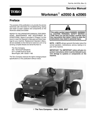
- 1. Part No. 04127SL (Rev. C) Service Manual WorkmanR e2050 & e2065 Preface The purpose of this publication is to provide the service technician with information for troubleshooting, testing and repair of major systems and components on the Workman e2050 and e2065. REFER TO THE OPERATOR’S MANUAL FOR OPER- ATING, MAINTENANCE AND ADJUSTMENT IN- STRUCTIONS. Space is provided in Chapter 2 of this book to insert the Operator’s Manuals and Parts Cata- logs for your machine. Replacement Operator’s Manu- als are available on the Internet at www.toro.com or by sending complete Model and Serial Number to: The Toro Company Attn. Technical Publications 8111 Lyndale Avenue South Bloomington, MN 55420–1196 The Toro Company reserves the right to change product specifications or this publication without notice. This safety symbol means DANGER, WARNING or CAUTION, PERSONAL SAFETY INSTRUC- TION. When you see this symbol, carefully read the instructions that follow. Failure to obey the instructions may result in personal injury. NOTE: A NOTE will give general information about the correct operation, maintenance, service, testing or re- pair of the machine. IMPORTANT: The IMPORTANT notice will give im- portant instructions which must be followed to pre- vent damage to systems or components on the machine. E The Toro Company – 2004, 2006, 2007
- 2. Workman e2050/e2065 Table Of Contents Chapter 1 – Safety Safety Instructions 1 – 2. . . . . . . . . . . . . . . . . . . . . . . . . . Jacking and Other Instructions 1 – 4. . . . . . . . . . . . . . . Safety and Instruction Decals 1 – 5. . . . . . . . . . . . . . . . Chapter 2 – Product Records and Maintenance Product Records 2 – 1. . . . . . . . . . . . . . . . . . . . . . . . . . . Equivalents and Conversions 2 – 2. . . . . . . . . . . . . . . . Torque Specifications 2 – 3. . . . . . . . . . . . . . . . . . . . . . . Maintenance 2 – 7. . . . . . . . . . . . . . . . . . . . . . . . . . . . . . . Chapter 3 – Electrical System Electrical Diagrams 3 – 2. . . . . . . . . . . . . . . . . . . . . . . . . General Information 3 – 3. . . . . . . . . . . . . . . . . . . . . . . . Vehicle Operation 3 – 4. . . . . . . . . . . . . . . . . . . . . . . . . . Special Tools 3 – 5. . . . . . . . . . . . . . . . . . . . . . . . . . . . . . Troubleshooting 3 – 8. . . . . . . . . . . . . . . . . . . . . . . . . . . . Adjustments 3 – 11. . . . . . . . . . . . . . . . . . . . . . . . . . . . . . Component Testing 3 – 14. . . . . . . . . . . . . . . . . . . . . . . . Service and Repairs 3 – 28. . . . . . . . . . . . . . . . . . . . . . . LESTER ELECTRICAL TECHNICIAN SERVICE GUIDE Chapter 4 – Transaxle and Brakes Specifications 4 – 3. . . . . . . . . . . . . . . . . . . . . . . . . . . . . . Troubleshooting 4 – 4. . . . . . . . . . . . . . . . . . . . . . . . . . . . Adjustments 4 – 6. . . . . . . . . . . . . . . . . . . . . . . . . . . . . . . Service and Repairs 4 – 8. . . . . . . . . . . . . . . . . . . . . . . . SPICER OFF–HIGHWAY COMPONENTS MODEL 12 (ELECTRIC) MAINTENANCE MANUAL Chapter 5 – Chassis Specifications 5 – 2. . . . . . . . . . . . . . . . . . . . . . . . . . . . . . Troubleshooting 5 – 3. . . . . . . . . . . . . . . . . . . . . . . . . . . . Service and Repairs 5 – 5. . . . . . . . . . . . . . . . . . . . . . . . Chapter 6 – Electrical Diagrams Electrical Schematic 6 – 3. . . . . . . . . . . . . . . . . . . . . . . . Electrical Circuit Drawings 6 – 4. . . . . . . . . . . . . . . . . . . Electrical Harness Drawings 6 – 7. . . . . . . . . . . . . . . . . SafetyProductRecords andMaintenance ElectricalChassisElectrical Diagrams Transaxleand SystemBrakes
- 3. Workman e2050/e2065 Page 1 – 1 Safety (Rev. B) Chapter 1 Safety Table of Contents SAFETY INSTRUCTIONS 2. . . . . . . . . . . . . . . . . . . . . . Before Operating 2. . . . . . . . . . . . . . . . . . . . . . . . . . . . While Operating 2. . . . . . . . . . . . . . . . . . . . . . . . . . . . Maintenance and Service 3. . . . . . . . . . . . . . . . . . . . JACKING AND OTHER INSTRUCTIONS 4. . . . . . . . Jacking Vehicle 4. . . . . . . . . . . . . . . . . . . . . . . . . . . . . Towing Vehicle 4. . . . . . . . . . . . . . . . . . . . . . . . . . . . . . Transporting Vehicle 4. . . . . . . . . . . . . . . . . . . . . . . . . SAFETY AND INSTRUCTION DECALS 5. . . . . . . . . . Safety
- 4. Workman e2050/e2065Page 1 – 2Safety (Rev. B) Safety Instructions The Workman e2050 and e2065 are designed and tested to offer safe service when operated and main- tained properly. Although hazard control and accident prevention are partially dependent upon the design and configuration of the machine, these factors are also de- pendent upon the awareness, concern and proper train- ing of the personnel involved in the operation, transport, maintenance and storage of the machine. Improper use or maintenance of the machine can result in injury or death. To reduce the potential for injury or death, comply with the following safety instructions. WARNING To reduce the potential for injury or death, comply with the following safety instructions. Before Operating 1. Read and understand the contents of the Operator’s Manual before starting and operating the machine. Be- come familiar with the controls and know how to stop the machine quickly. A replacement Operator’s Manual is available on the Internet at www.Toro.com or by sending the complete model and serial number to: The Toro Company Attn. Technical Publications 8111 Lyndale Avenue South Bloomington, Minnesota 55420–1196 2. Keep all shields, safety devices and decals in place. If a shield, safety device or decal is defective, illegible or damaged, repair or replace it before operating the ma- chine. Also tighten any loose nuts, bolts or screws to en- sure machine is in safe operating condition. While Operating WARNING The Workman e2050 and e2065 are off–highway vehicles only. They are not designed, equipped or manufactured for use on public streets, roads or highways. 1. Sit on the operator seat when starting and operating the vehicle. 2. Before starting the vehicle: A. Make sure that the battery charger is discon- nected from the vehicle charger receptacle. B. Engage the parking brake. C. Make sure accelerator pedal is not depressed. D. Check position of forward/reverse switch and Hi/ Low speed switch. 3. Before getting off the operator seat: A. Stop vehicle, turn on/off switch OFF and remove key from switch. B. Set parking brake. 4. If vehicle is parked on incline, chock or block the wheels after getting off the vehicle.
- 5. Workman e2050/e2065 Page 1 – 3 Safety (Rev. B) Maintenance and Service 1. Before servicing or making adjustments to the ve- hicle, stop vehicle, turn on/off switch to OFF, engage parking brake and remove key from the on/off switch. 2. Make sure machine is in safe operating condition by keeping all nuts, bolts and screws tight. 3. Do not use open pans of flammable cleaning fluids for cleaning parts. 4. Keep battery area free of excessive grease, grass, leaves and dirt. 5. Disconnect batteries before servicing the machine. Carefully remove one of the battery cables from the bat- tery pack as the first step in any repair. Once a battery cable has been removed, the electrical system on the vehicle can be safely worked on. Take care during re- pairs, however, to not allow tools or vehicle components to complete the battery circuit that was opened with the cable removal. Reattach the removed cable to the bat- tery pack as the last step in any repair. 6. When using metal, uninsulated tools around batter- ies, do not allow tools to contact both positive and nega- tive battery terminals simultaneously. 7. Remove jewelry and watches before servicing elec- trical components of the vehicle. 8. Battery acid is poisonous and can cause burns. Avoid contact with skin, eyes and clothing. Protect your face, eyes and clothing when working with batteries. 9. Battery gases can explode. Keep cigarettes, sparks and flames away from the batteries. Always service, store and charge the vehicle batteries in a well ventilated area. 10.Never use an open flame to check level or leakage of battery electrolyte. 11.When connecting the battery charger to the vehicle, connect the charger cord to the vehicle charger recep- tacle before plugging the charger power cord into an outlet. After charging the vehicle batteries, unplug the charger power cord from the outlet before disconnecting the charger cord from the vehicle charger receptacle. 12.If major repairs are ever needed or assistance is de- sired, contact an Authorized Toro Distributor. 13.To assure optimum performance and continued safety of the machine, use genuine Toro replacement parts and accessories. Replacement parts and acces- sories made by other manufacturers may result in non- conformance with safety standards and the warranty may be voided. 14.When raising the machine to change tires or to per- form other service, use correct blocks, hoists and jacks. Make sure machine is parked on a solid level surface such as a concrete floor. Prior to raising the machine, re- move any attachments that may interfere with the safe and proper raising of the machine. Always chock or block wheels. Use jack stands or solid wood blocks to support the raised machine. If the machine is not proper- ly supported by blocks or jack stands, the machine may move or fall, which may result in personal injury (see Jacking Instructions in the Operator’s Manual and in this Chapter). Safety
- 6. Workman e2050/e2065Page 1 – 4Safety (Rev. B) Jacking and Other Instructions Jacking Vehicle DANGER POTENTIAL HAZARD • A vehicle that is not properly supported may become unstable. WHAT CAN HAPPEN • The vehicle may move or fall. Personal injury or damage to the machine may result. HOW TO AVOID THE HAZARD • Make sure vehicle is parked on a solid level surface, such as a concrete floor. • Make sure On/Off switch is OFF and key is removed from the switch before getting off the vehicle. • Before raising the vehicle, remove any attachments that may interfere with the safe and proper raising of the vehicle. • Always chock or block wheels to prevent the vehicle from rolling. • Make sure proper hoists, solid wooden blocks and jack stands are used to raise and support the vehicle. Jacking Locations 1. Jack front of the vehicle on the front of the frame be- hind the towing tongue (Fig. 1). 2. Jack rear of the vehicle under each rear axle tube. Do not jack vehicle below the transaxle case (Fig. 2). 1. Front frame 2. Towing tongue Figure 1 21 1. Axle tube 2. Transaxle case Figure 2 2 11 Towing Vehicle IMPORTANT: Frequent or long distance towing of the Workman e2050/e2065 is not recommended. In case of emergency, the vehicle can be towed for a short distance. See Operator’s Manual for towing in- formation. IMPORTANT: If vehicle is towed, make sure that on/ off switch is in the OFF position and key is removed from switch. Transporting Vehicle When moving the vehicle long distances, use a trailer or flatbed truck. Make sure vehicle is secured to the trailer properly. See Operator’s Manual for transport informa- tion.
- 7. Workman e2050/e2065 Page 1 – 5 Safety (Rev. B) Safety and Instruction Decals There are several safety and instruction decals attached to your Workman vehicle. If any decal becomes illegible or damaged, install a new decal. Part numbers are listed in the Parts Catalog. Order replacement decals from your Authorized Toro Distributor. Safety
- 8. Workman e2050/e2065 Page 2 – 1 Product Records and Maintenance (Rev. B) Chapter 2 Product Records and Maintenance Table of Contents PRODUCT RECORDS 1. . . . . . . . . . . . . . . . . . . . . . . . . EQUIVALENTS AND CONVERSIONS 2. . . . . . . . . . . Decimal and Millimeter Equivalents 2. . . . . . . . . . . . U.S. to Metric Conversions 2. . . . . . . . . . . . . . . . . . . TORQUE SPECIFICATIONS 3. . . . . . . . . . . . . . . . . . . Fastener Identification 3. . . . . . . . . . . . . . . . . . . . . . . Standard Torque for Dry, Zinc Plated and Steel Fasteners (Inch Series) 4. . . . . . . . . . . . . . . Standard Torque for Dry, Zinc Plated and Steel Fasteners (Metric Fasteners) 5. . . . . . . . . . Other Torque Specifications 6. . . . . . . . . . . . . . . . . . Conversion Factors 6. . . . . . . . . . . . . . . . . . . . . . . . . MAINTENANCE 7. . . . . . . . . . . . . . . . . . . . . . . . . . . . . . Product Records Insert Operator’s Manual and Parts Catalog for your Workman vehicle at the end of this chapter. Additionally, if any optional equipment or accessories have been installed to your Workman, insert the Installation In- structions, Operator’s Manuals and Parts Catalogs for those options at the end of this chapter. ProductRecords andMaintenance
- 9. 0.09375 Workman e2050/e2065Page 2 – 2Product Records and Maintenance (Rev. B) Equivalents and Conversions
- 10. Workman e2050/e2065 Page 2 – 3 Product Records and Maintenance (Rev. B) Torque Specifications Recommended fastener torque values are listed in the following tables. For critical applications, as determined by Toro, either the recommended torque or a torque that is unique to the application is clearly identified and spe- cified in this Service Manual. These Torque Specifications for the installation and tightening of fasteners shall apply to all fasteners which do not have a specific requirement identified in this Ser- vice Manual. The following factors shall be considered when applying torque: cleanliness of the fastener, use of a thread sealant (Loctite), degree of lubrication on the fastener, presence of a prevailing torque feature, hard- ness of the surface underneath the fastener’s head or similar condition which affects the installation. As noted in the following tables, torque values should be reduced by 25% for lubricated fasteners to achieve the similar stress as a dry fastener. Torque values may also have to be reduced when the fastener is threaded into aluminum or brass. The specific torque value should be determined based on the aluminum or brass material strength, fastener size, length of thread en- gagement, etc. The standard method of verifying torque shall be per- formed by marking a line on the fastener (head or nut) and mating part, then back off fastener 1/4 of a turn. Measure the torque required to tighten the fastener until the lines match up. Fastener Identification Figure 1 Grade 1 Grade 5 Grade 8 Inch Series Bolts and Screws Figure 2 Class 8.8 Class 10.9 Metric Bolts and Screws ProductRecords andMaintenance
- 11. Workman e2050/e2065Page 2 – 4Product Records and Maintenance (Rev. B) Standard Torque for Dry, Zinc Plated and Steel Fasteners (Inch Series) Thread Size Grade 1, 5, & 8 with Thin Height Nuts SAE Grade 1 Bolts, Screws, Studs & Sems with Regular Height Nuts (SAE J995 Grade 2 or Stronger Nuts) SAE Grade 5 Bolts, Screws, Studs & Sems with Regular Height Nuts (SAE J995 Grade 2 or Stronger Nuts) SAE Grade 8 Bolts, Screws, Studs & Sems with Regular Height Nuts (SAE J995 Grade 5 or Stronger Nuts) in–lb in–lb N–cm in–lb N–cm in–lb N–cm # 6 – 32 UNC 10 + 2 13 + 2 147 + 23 15 + 2 170 + 20 23 + 2 260 + 20 # 6 – 40 UNF 10 + 2 13 + 2 147 + 23 17 + 2 190 + 20 25 + 2 280 + 20 # 8 – 32 UNC 13 + 2 25 + 5 282 + 30 29 + 3 330 + 30 41 + 4 460 + 45 # 8 – 36 UNF 13 + 2 25 + 5 282 + 30 31 + 3 350 + 30 43 + 4 485 + 45 # 10 – 24 UNC 18 + 2 30 + 5 339 + 56 42 + 4 475 + 45 60 + 6 675 + 70 # 10 – 32 UNF 18 + 2 30 + 5 339 + 56 48 + 4 540 + 45 68 + 6 765 + 70 1/4 – 20 UNC 48 + 7 53 + 7 599 + 79 100 + 10 1125 + 100 140 + 15 1580 + 170 1/4 – 28 UNF 53 + 7 65 + 10 734 + 113 115 + 10 1300 + 100 160 + 15 1800 + 170 5/16 – 18 UNC 115 + 15 105 + 17 1186 + 169 200 + 25 2250 + 280 300 + 30 3390 + 340 5/16 – 24 UNF 138 + 17 128 + 17 1446 + 192 225 + 25 2540 + 280 325 + 30 3670 + 340 ft–lb ft–lb N–m ft–lb N–m ft–lb N–m 3/8 – 16 UNC 16 + 2 16 + 2 22 + 3 30 + 3 41 + 4 43 + 4 58 + 5 3/8 – 24 UNF 17 + 2 18 + 2 24 + 3 35 + 3 47 + 4 50 + 4 68 + 5 7/16 – 14 UNC 27 + 3 27 + 3 37 + 4 50 + 5 68 + 7 70 + 7 95 + 9 7/16 – 20 UNF 29 + 3 29 + 3 39 + 4 55 + 5 75 + 7 77 + 7 104 + 9 1/2 – 13 UNC 30 + 3 48 + 7 65 + 9 75 + 8 102 + 11 105 + 10 142 + 14 1/2 – 20 UNF 32 + 3 53 + 7 72 + 9 85 + 8 115 + 11 120 + 10 163 + 14 5/8 – 11 UNC 65 + 10 88 + 12 119 + 16 150 + 15 203 + 20 210 + 20 285 + 27 5/8 – 18 UNF 75 + 10 95 + 15 129 + 20 170 + 15 230 + 20 240 + 20 325 + 27 3/4 – 10 UNC 93 + 12 140 + 20 190 + 27 265 + 25 359 + 34 375 + 35 508 + 47 3/4 – 16 UNF 115 + 15 165 + 25 224 + 34 300 + 25 407 + 34 420 + 35 569 + 47 7/8 – 9 UNC 140 + 20 225 + 25 305 + 34 430 + 45 583 + 61 600 + 60 813 + 81 7/8 – 14 UNF 155 + 25 260 + 30 353 + 41 475 + 45 644 + 61 660 + 60 895 + 81 NOTE: Reduce torque values listed in the table above by 25% for lubricated fasteners. Lubricated fasteners are defined as threads coated with a lubricant such as oil, graphite or thread sealant such as Loctite. NOTE: Torque values may have to be reduced when installing fasteners into threaded aluminum or brass. The specific torque value should be determined based on the fastener size, the aluminum or base material strength, length of thread engagement, etc. NOTE: The nominal torque values listed above for Grade 5 and 8 fasteners are based on 75% of the mini- mum proof load specified in SAE J429. The tolerance is approximately + 10% of the nominal torque value. Thin height nuts include jam nuts.
- 12. Workman e2050/e2065 Page 2 – 5 Product Records and Maintenance (Rev. B) Standard Torque for Dry, Zinc Plated and Steel Fasteners (Metric Fasteners) Thread Size Class 8.8 Bolts, Screws and Studs with Regular Height Nuts Class 10.9 Bolts, Screws and Studs with Regular Height NutsThread Size Regular Height Nuts (Class 8 or Stronger Nuts) Regular Height Nuts (Class 10 or Stronger Nuts) M5 X 0.8 57 + 5 in–lb 640 + 60 N–cm 78 + 7 in–lb 885 + 80 N–cm M6 X 1.0 96 + 9 in–lb 1018 + 100 N–cm 133 + 13 in–lb 1500 + 150 N–cm M8 X 1.25 19 + 2 ft–lb 26 + 3 N–m 27 + 2 ft–lb 36 + 3 N–m M10 X 1.5 38 + 4 ft–lb 52 + 5 N–m 53 + 5 ft–lb 72 + 7 N–m M12 X 1.75 66 + 7 ft–lb 90 + 10 N–m 92 + 9 ft–lb 125 + 12 N–m M16 X 2.0 166 + 15 ft–lb 225 + 20 N–m 229 + 22 ft–lb 310 + 30 N–m M20 X 2.5 325 + 33 ft–lb 440 + 45 N–m 450 + 37 ft–lb 610 + 50 N–m NOTE: Reduce torque values listed in the table above by 25% for lubricated fasteners. Lubricated fasteners are defined as threads coated with a lubricant such as oil, graphite or thread sealant such as Loctite. NOTE: Torque values may have to be reduced when installing fasteners into threaded aluminum or brass. The specific torque value should be determined based on the fastener size, the aluminum or base material strength, length of thread engagement, etc. NOTE: The nominal torque values listed above are based on 75% of the minimum proof load specified in SAE J1199. The tolerance is approximately + 10% of the nominal torque value. ProductRecords andMaintenance
- 13. Workman e2050/e2065Page 2 – 6Product Records and Maintenance (Rev. B) Other Torque Specifications SAE Grade 8 Steel Set Screws Thread Size Recommended Torque Thread Size Square Head Hex Socket 1/4 – 20 UNC 140 + 20 in–lb 73 + 12 in–lb 5/16 – 18 UNC 215 + 35 in–lb 145 + 20 in–lb 3/8 – 16 UNC 35 + 10 ft–lb 18 + 3 ft–lb 1/2 – 13 UNC 75 + 15 ft–lb 50 + 10 ft–lb Thread Cutting Screws (Zinc Plated Steel) Type 1, Type 23 or Type F Thread Size Baseline Torque* No. 6 – 32 UNC 20 + 5 in–lb No. 8 – 32 UNC 30 + 5 in–lb No. 10 – 24 UNC 38 + 7 in–lb 1/4 – 20 UNC 85 + 15 in–lb 5/16 – 18 UNC 110 + 20 in–lb 3/8 – 16 UNC 200 + 100 in–lb Wheel Bolts and Lug Nuts Thread Size Recommended Torque** 7/16 – 20 UNF Grade 5 65 + 10 ft–lb 88 + 14 N–m 1/2 – 20 UNF Grade 5 80 + 10 ft–lb 108 + 14 N–m M12 X 1.25 Class 8.8 80 + 10 ft–lb 108 + 14 N–m M12 X 1.5 Class 8.8 80 + 10 ft–lb 108 + 14 N–m ** For steel wheels and non–lubricated fasteners. Thread Cutting Screws (Zinc Plated Steel) Thread Size Threads per Inch Baseline Torque*Size Type A Type B Baseline Torque* No. 6 18 20 20 + 5 in–lb No. 8 15 18 30 + 5 in–lb No. 10 12 16 38 + 7 in–lb No. 12 11 14 85 + 15 in–lb * Hole size, material strength, material thickness & finish must be considered when determining specific torque values. All torque values are based on non–lubricated fasteners. Conversion Factors in–lb X 11.2985 = N–cm N–cm X 0.08851 = in–lb ft–lb X 1.3558 = N–m N–m X 0.7376 = ft–lb
- 14. Workman e2050/e2065 Page 2 – 7 Product Records and Maintenance (Rev. B) Maintenance Maintenance procedures and recommended service in- tervals for the Workman e2050 and e2065 are covered in the Operator’s Manual. Refer to that publication when performing regular vehicle maintenance. ProductRecords andMaintenance
- 15. Workman e2050/e2065 Page 3 – 1 Electrical System (Rev. B) Chapter 3 Electrical System Table of Contents ELECTRICAL DIAGRAMS 2. . . . . . . . . . . . . . . . . . . . . GENERAL INFORMATION 3. . . . . . . . . . . . . . . . . . . . . Opening Battery Circuit 3. . . . . . . . . . . . . . . . . . . . . . VEHICLE OPERATION 4. . . . . . . . . . . . . . . . . . . . . . . . SPECIAL TOOLS 5. . . . . . . . . . . . . . . . . . . . . . . . . . . . . TROUBLESHOOTING 8. . . . . . . . . . . . . . . . . . . . . . . . . General Run Problems 8. . . . . . . . . . . . . . . . . . . . . . Battery Charger Operation 9. . . . . . . . . . . . . . . . . . . Battery Charger Problems 10. . . . . . . . . . . . . . . . . . . ADJUSTMENTS 11. . . . . . . . . . . . . . . . . . . . . . . . . . . . . . Accelerator Switch Adjustment 11. . . . . . . . . . . . . . . . Accelerator Potentiometer Adjustment 12. . . . . . . . Accelerator System Calibration 13. . . . . . . . . . . . . . COMPONENT TESTING 14. . . . . . . . . . . . . . . . . . . . . . On/Off Switch 14. . . . . . . . . . . . . . . . . . . . . . . . . . . . . . Battery Discharge Indicator and Hour Meter Gauge 15. . . . . . . . . . . . . . . . . . . . . . . . . . . . Vehicle Direction (Forward/Reverse) and Headlight Switches 16. . . . . . . . . . . . . . . . . . . . . . . Vehicle Status Light 17. . . . . . . . . . . . . . . . . . . . . . . . Supervisor Speed Limit Switch (Workman e2050)18 Supervisor Speed Limit Switch (Workman e2065)18 Audio Alarm (Reverse) 18. . . . . . . . . . . . . . . . . . . . . . Charger Interlock Switch 19. . . . . . . . . . . . . . . . . . . . Main and Accessories Contactors 20. . . . . . . . . . . . Fuses 22. . . . . . . . . . . . . . . . . . . . . . . . . . . . . . . . . . . . Fusible Links 23. . . . . . . . . . . . . . . . . . . . . . . . . . . . . . Accelerator Switch 24. . . . . . . . . . . . . . . . . . . . . . . . . Accelerator Potentiometer 25. . . . . . . . . . . . . . . . . . . Controller 26. . . . . . . . . . . . . . . . . . . . . . . . . . . . . . . . . SERVICE AND REPAIRS 28. . . . . . . . . . . . . . . . . . . . . Battery Service 28. . . . . . . . . . . . . . . . . . . . . . . . . . . . Battery Specifications 28. . . . . . . . . . . . . . . . . . . . . Removal 29. . . . . . . . . . . . . . . . . . . . . . . . . . . . . . . . Installation 29. . . . . . . . . . . . . . . . . . . . . . . . . . . . . . . Charging 30. . . . . . . . . . . . . . . . . . . . . . . . . . . . . . . . Inspection and Maintenance 30. . . . . . . . . . . . . . . Testing 31. . . . . . . . . . . . . . . . . . . . . . . . . . . . . . . . . . Battery Storage 32. . . . . . . . . . . . . . . . . . . . . . . . . . Traction Motor Brushes 33. . . . . . . . . . . . . . . . . . . . . Traction Motor 34. . . . . . . . . . . . . . . . . . . . . . . . . . . . . Traction Motor Service 38. . . . . . . . . . . . . . . . . . . . . . Battery Charger 42. . . . . . . . . . . . . . . . . . . . . . . . . . . . LESTER ELECTRICAL TECHNICIAN SERVICE GUIDE Electrical System
- 16. Workman e2050/e2065Page 3 – 2Electrical System (Rev. B) Electrical Diagrams The electrical schematic, circuit drawings and wire har- ness drawings for the Workman e2050 and e2065 are located in Chapter 6 – Electrical Diagrams.
- 17. Workman e2050/e2065 Page 3 – 3 Electrical System (Rev. B) General Information The Workman e2050 and e2065 use a 48 volt DC elec- trical system that is an isolated circuit. The vehicle frame is not used for any ground connections. The vehicle controller monitors operator and vehicle in- puts to determine voltage to the traction motor. If a prob- lem exists that will prevent normal vehicle operation, an LED on the controller and the vehicle status light on the dash panel will flash a fault code to assist in identifying the problem. After performing any repair on electrical components on the vehicle, make sure that wiring is routed and secured so as to prevent abrasion or contact with moving parts. Opening Battery Circuit To prevent allowing a current path through tools used during vehicle electrical circuit repairs, remove one of the battery cables from the battery pack as the first step in any repair (Fig. 1). Once a cable has been removed, the electrical system on the vehicle can be safely worked on. Take care during repairs, however, to not al- low tools or vehicle components to complete the battery circuit that was opened with the cable removal. Reattach the removed cable to the battery pack as the last step in any repair. Secure cable on each battery ter- minal with lock washer and nut. Torque nuts from 115 to 125 in–lb (13 to 14.1 N–m). Battery pack cable routing is shown in Figure 2. Figure 1 1. Negative cable to vehicle 2. Positive cable to vehicle Figure 2 A 4 1 2 Electrical System
- 18. Workman e2050/e2065Page 3 – 4Electrical System (Rev. B) Vehicle Operation The Workman e2050 and e2065 electrical system use a 48 volt battery pack, an electric traction motor, a ve- hicle controller and numerous other electrical compo- nents to allow vehicle operation. Eight, 6 volt, deep cycle batteries that are connected in series provide current for a 48 volt DC, high torque trac- tion motor, the vehicle controller and vehicle accesso- ries (headlights, horn, various optional accessories). The batteries are discharged as the vehicle is used so charging the batteries after using the vehicle is neces- sary. A battery discharge indicator gauge on the dash provides the operator with information on battery charge level. Demands on the vehicle during use (speed, pay- load, incline use), battery condition (age, charge level), ambient temperature and vehicle condition will all put constraints on how long a vehicle can be used before the batteries are discharged. An automatic, 115 VAC (230 VAC on international mod- els) battery charger is included with the vehicle. An inter- lock switch on the vehicle charger receptacle prevents the vehicle from operating when the charger cord is plugged into the vehicle. The electric traction motor directly drives a double re- duction transaxle with differential. Operator inputs for forward/reverse, supervisor switch position (high or low speed) and accelerator pedal position are used by the controller to determine voltage to the traction motor. The traction motor is cooled with an external fan. Addi- tionally, the motor is protected from overheating by a thermal switch in the motor housing. If unsafe motor temperature is sensed by the switch, the controller is signaled to limit vehicle speed and torque until the motor temperature reduces to a normal level. The vehicle controller is a sealed electronic logic device that uses inputs from several vehicle components to control motor speed and direction. These inputs include several switches (on/off, forward/reverse, accelerator, supervisor, charger), a motor temperature sensor, an accelerator pedal potentiometer and the vehicle contac- tor (solenoid). The controller also provides regenerative braking to assist in slowing the vehicle. The controller has fault detection capabilities to help identify system problems. Battery current is available to the controller whenever the on/off switch is ON which energizes the main contactor. A high current fuse protects this high current circuit. The Workman controller also provides a roll off warning in instances when the vehicle begins to move (roll away) after being stopped. On an incline and with the on/off switch in the ON position, if the vehicle starts moving, the alarm will sound warning the operator that the ve- hicle is moving. When the vehicle goes into this roll–off mode, regenerative braking will limit vehicle speed. Vehicle accessories include headlights, horn and op- tional electrical equipment. The accessories contactor (solenoid) on the vehicle provides battery current to these components when the on/off switch is ON. Fuses provide circuit protection for these accessories.
- 19. Thank you very much for your reading. Please Click Here. Then Get COMPLETE MANUAL. NO WAITING NOTE: If there is no response to click on the link above, please download the PDF document first and then click on it.
- 20. Workman e2050/e2065 Page 3 – 5 Electrical System (Rev. B) Special Tools Multimeter The multimeter can test electrical components and cir- cuits for current, resistance or voltage. NOTE: Toro recommends the use of a DIGITAL Volt– Ohm–Amp multimeter when testing electrical circuits. The high impedance (internal resistance) of a digital me- ter in the voltage mode will make sure that excess cur- rent is not allowed through the meter. This excess current can cause damage to circuits not designed to carry it. NOTE: Workman e2050 and e2065 vehicles use a 48 volt, DC electrical system. If multimeter is not of the auto–range type, make sure to properly set multimeter range before performing any voltage test. Figure 3 Battery Terminal Protector Battery Terminal Protector (Toro Part No. 107–0392) is an aerosol spray that should be used on all battery and controller terminals to reduce corrosion problems. Apply terminal protector after cable has been secured to termi- nal. Figure 4 Dielectric Gel Dielectric gel (Toro Part No. 107–0342) should be used to prevent corrosion of connection terminals. To ensure complete coating of terminals, liberally apply gel to both component and wire harness connector, plug connector to component, unplug connector, reapply gel to both surfaces and reconnect harness connector to compo- nent. Connectors should be thoroughly packed with gel for effective results. Figure 5 Electrical System
- 21. Workman e2050/e2065Page 3 – 6Electrical System (Rev. B) Battery Watering Dispenser Use the battery watering dispenser when adding dis- tilled water to vehicle batteries. Obtain watering dis- penser locally. Figure 6 Battery Hydrometer Use the battery hydrometer when measuring specific gravity of battery electrolyte. Obtain hydrometer locally. Figure 7 Battery Lift Strap Use the battery lift strap to remove and install batteries from the vehicle. Lift strap allows use of case loops on battery tops as safe battery lifting points. Obtain battery lift strap locally. Figure 8
- 22. Workman e2050/e2065 Page 3 – 7 Electrical System (Rev. B) 36/48 Volt Battery Discharge Unit The 36/48 Volt Battery Discharge Unit (TOR4106) is rec- ommended for quick and accurate load testing for the batteries on the Workman e2050 and e2065. This tool is used to determine the capacity of the Workman bat- tery pack and also for finding faulty battery or batteries in the battery pack. Order the 36/48 Volt Battery Discharge Unit (TOR4106) from the TORO SPECIAL TOOLS AND APPLICA- TIONS GUIDE (COMMERCIAL PRODUCTS). Figure 9 Electrical System