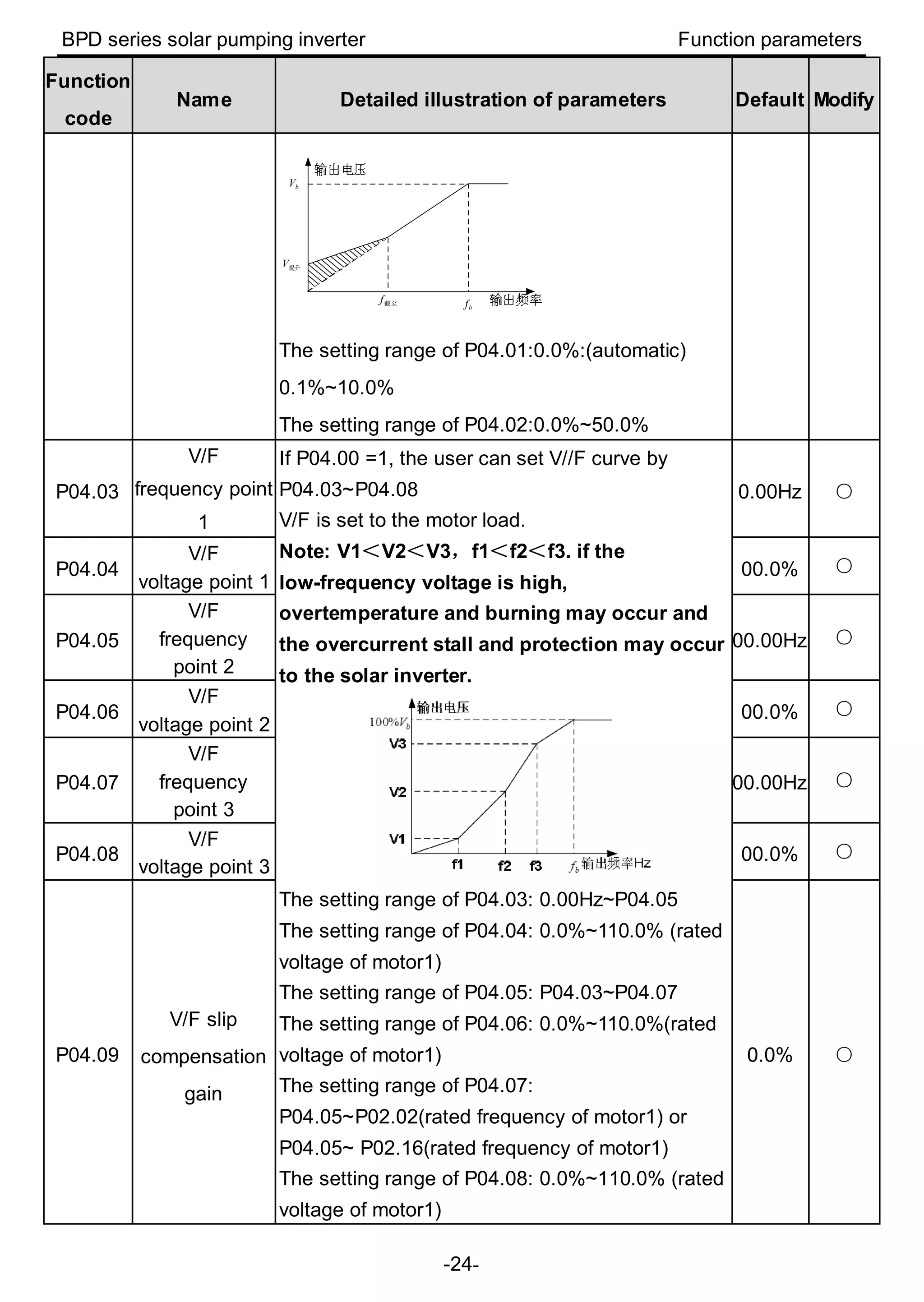
Download to read offline
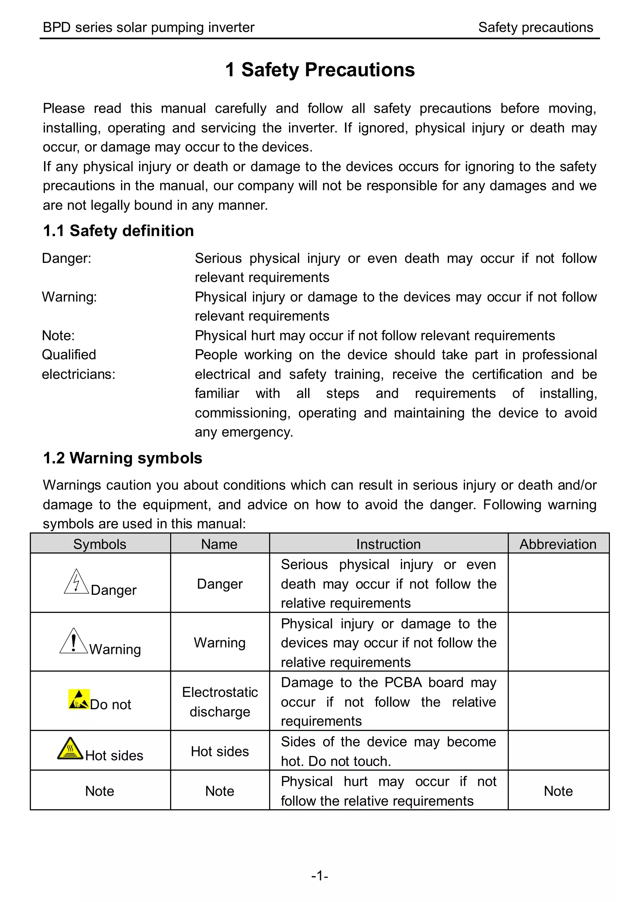


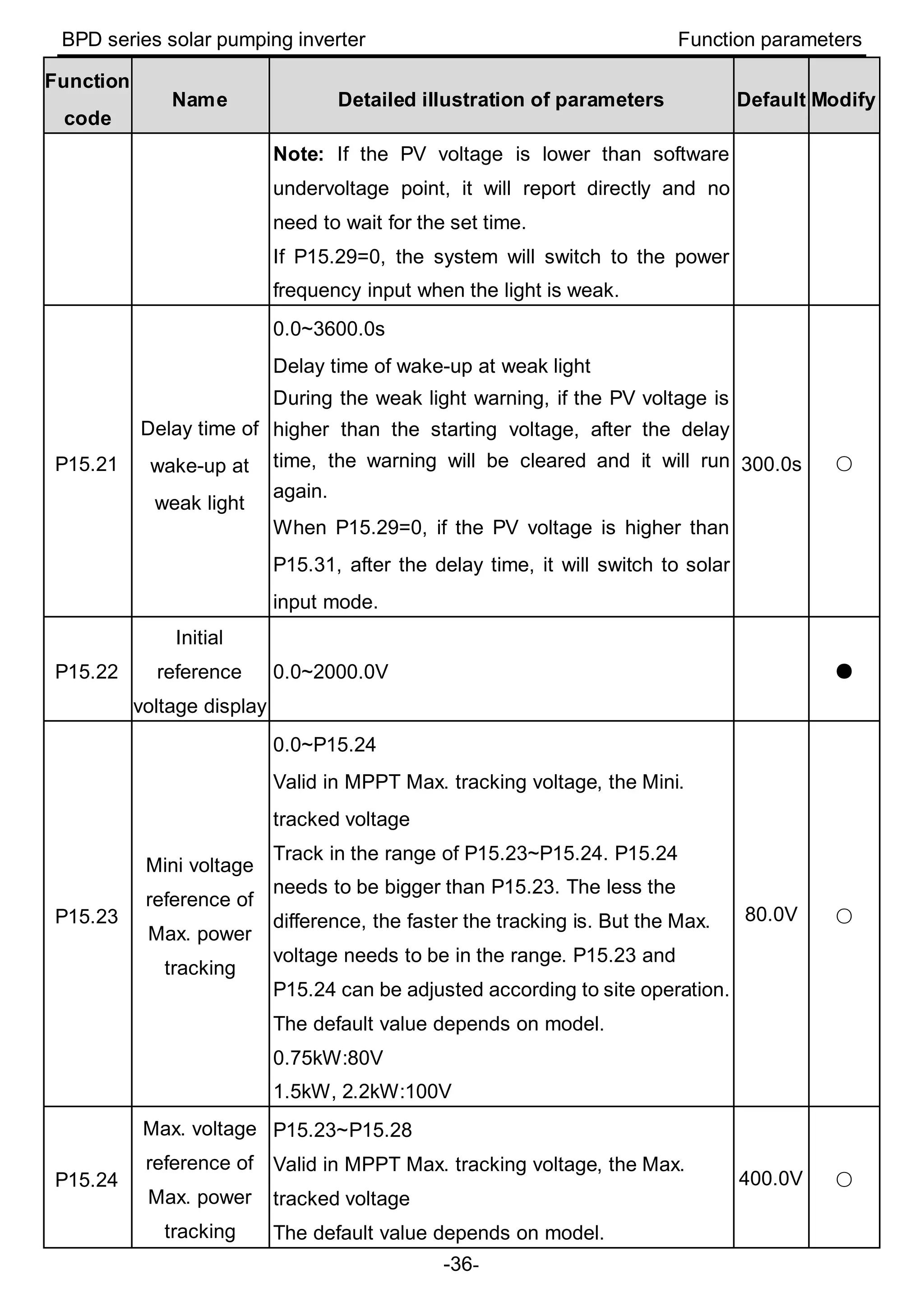
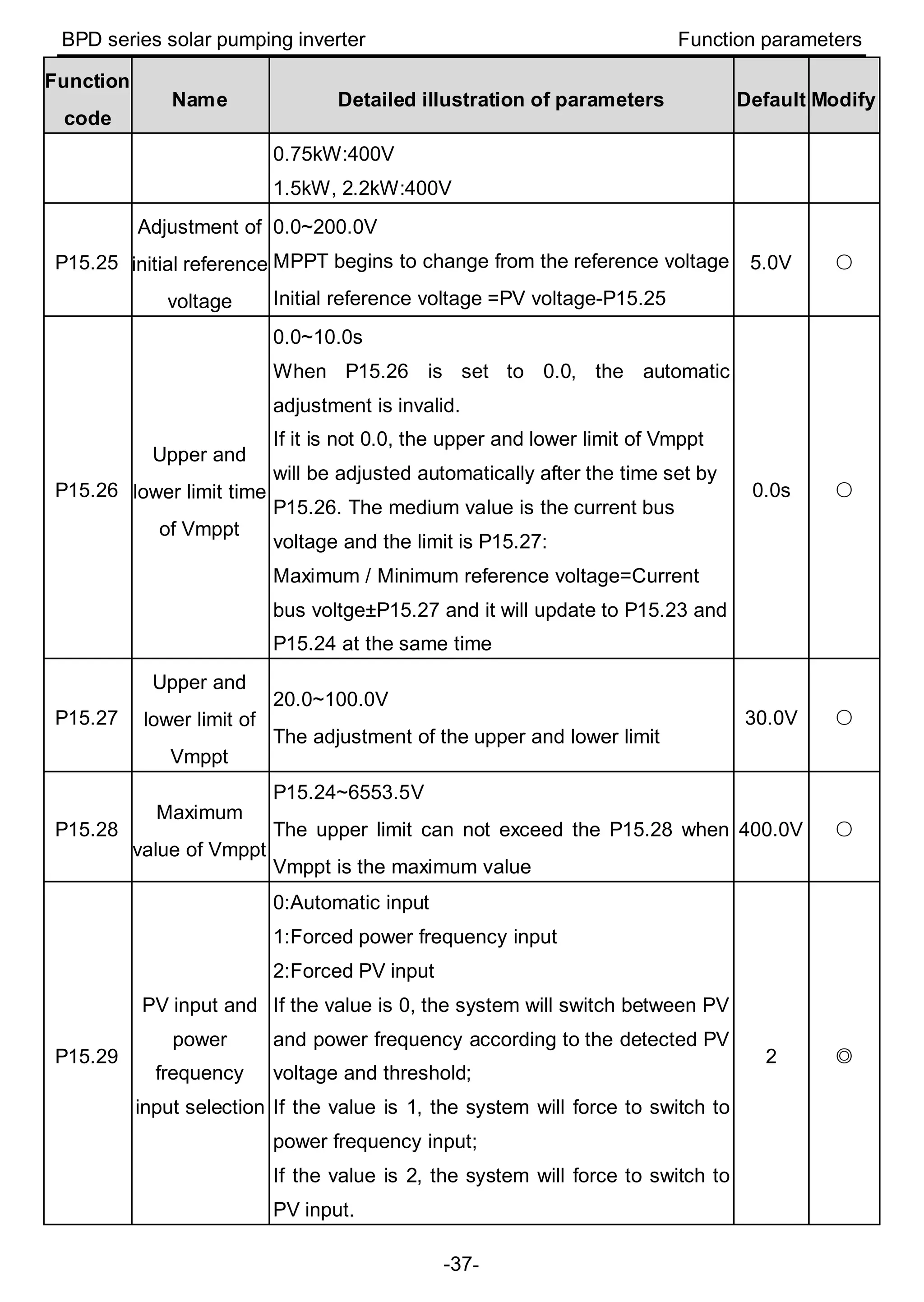
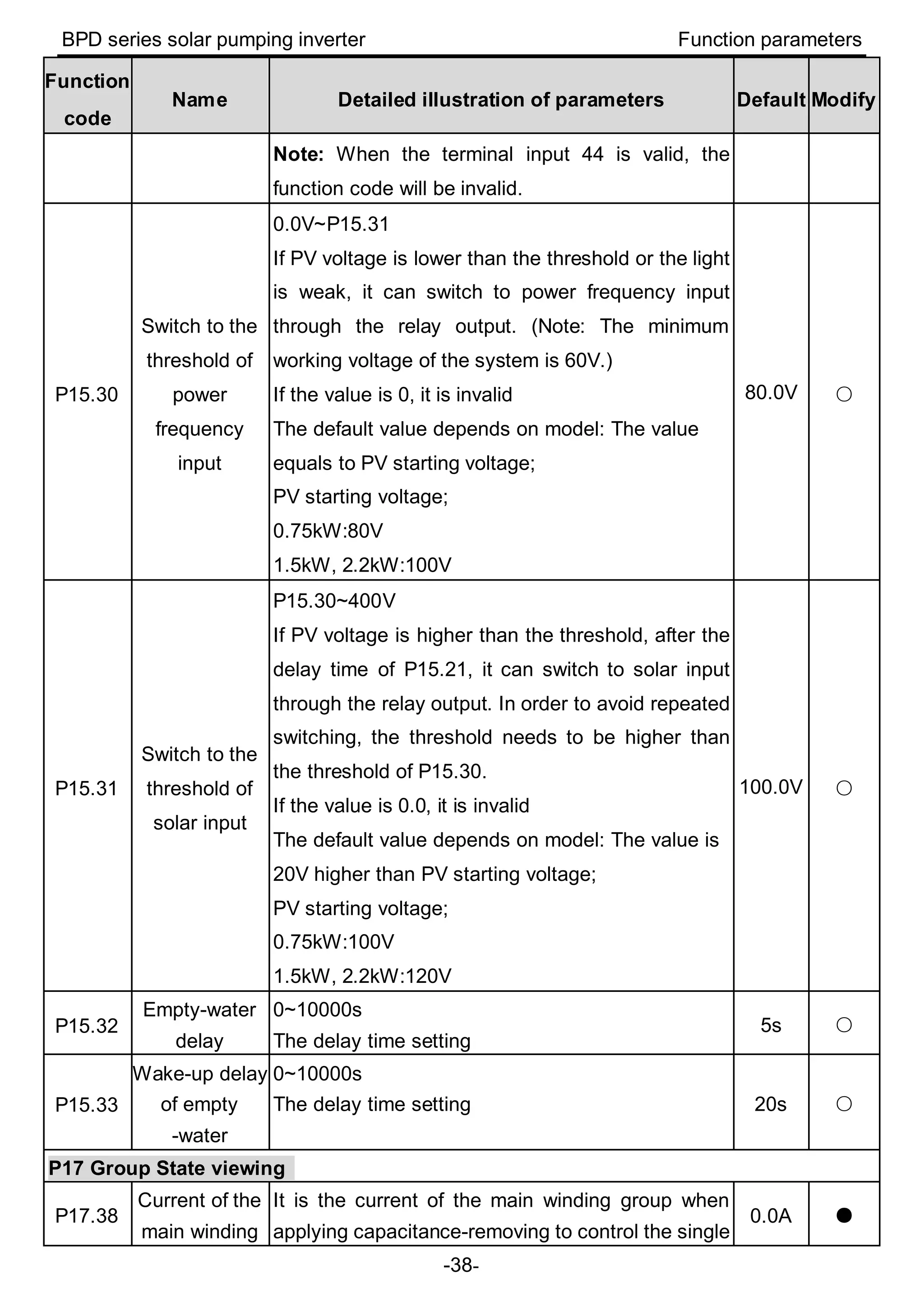
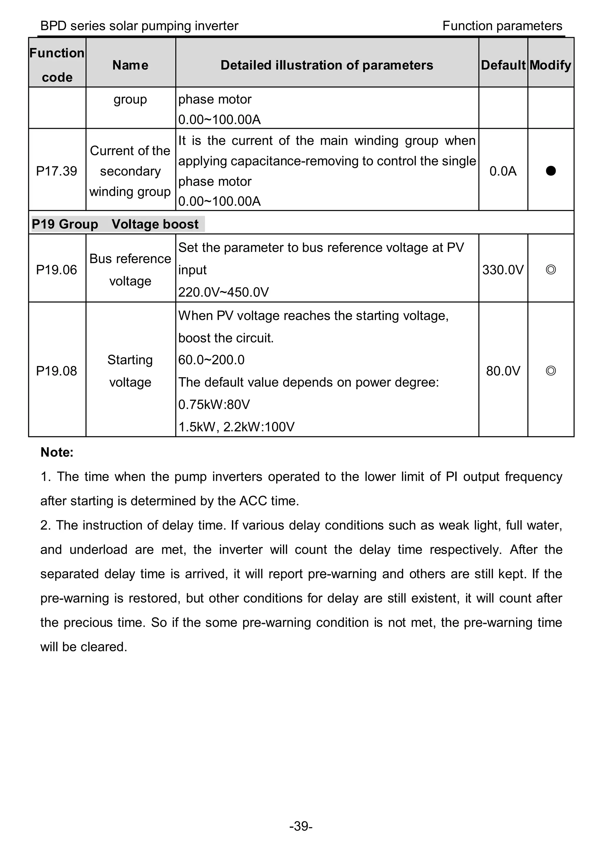
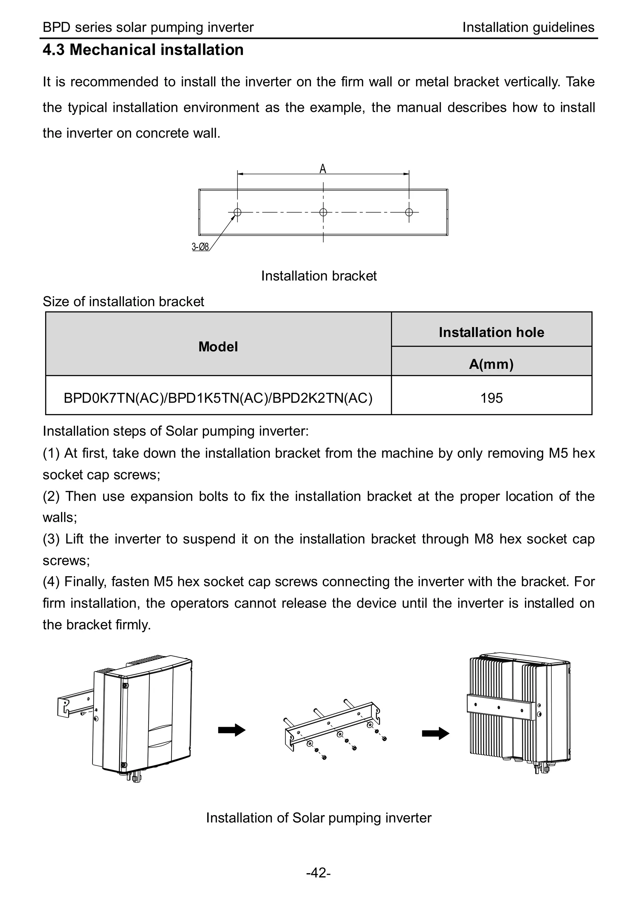
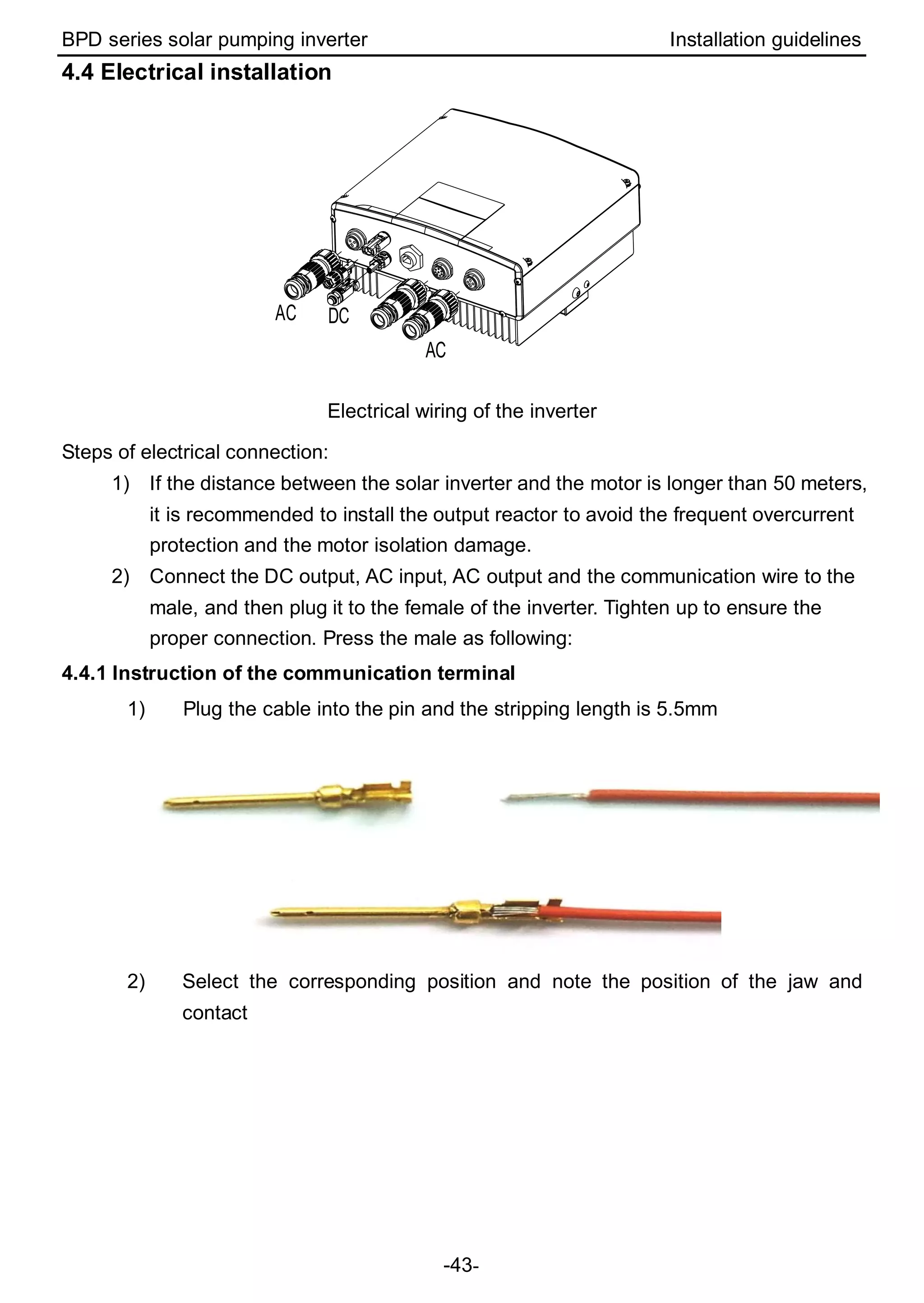
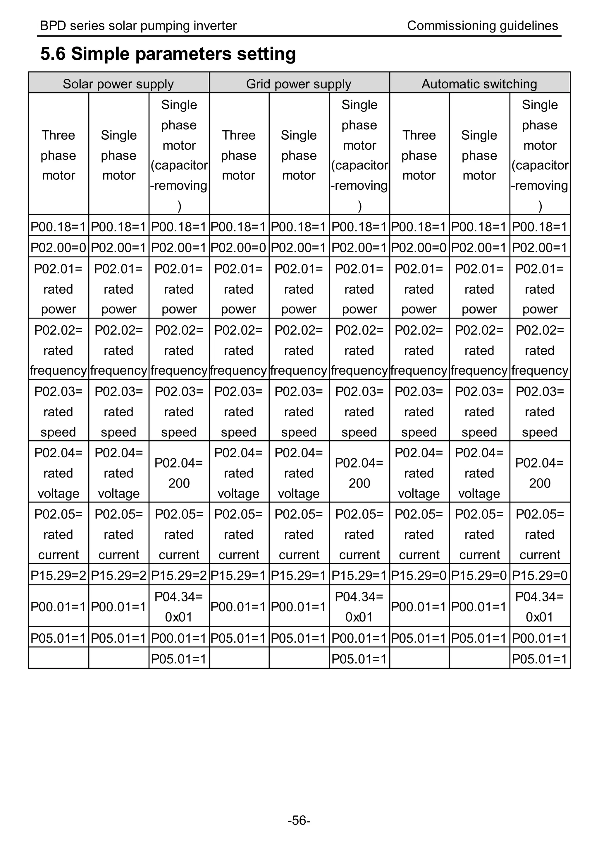
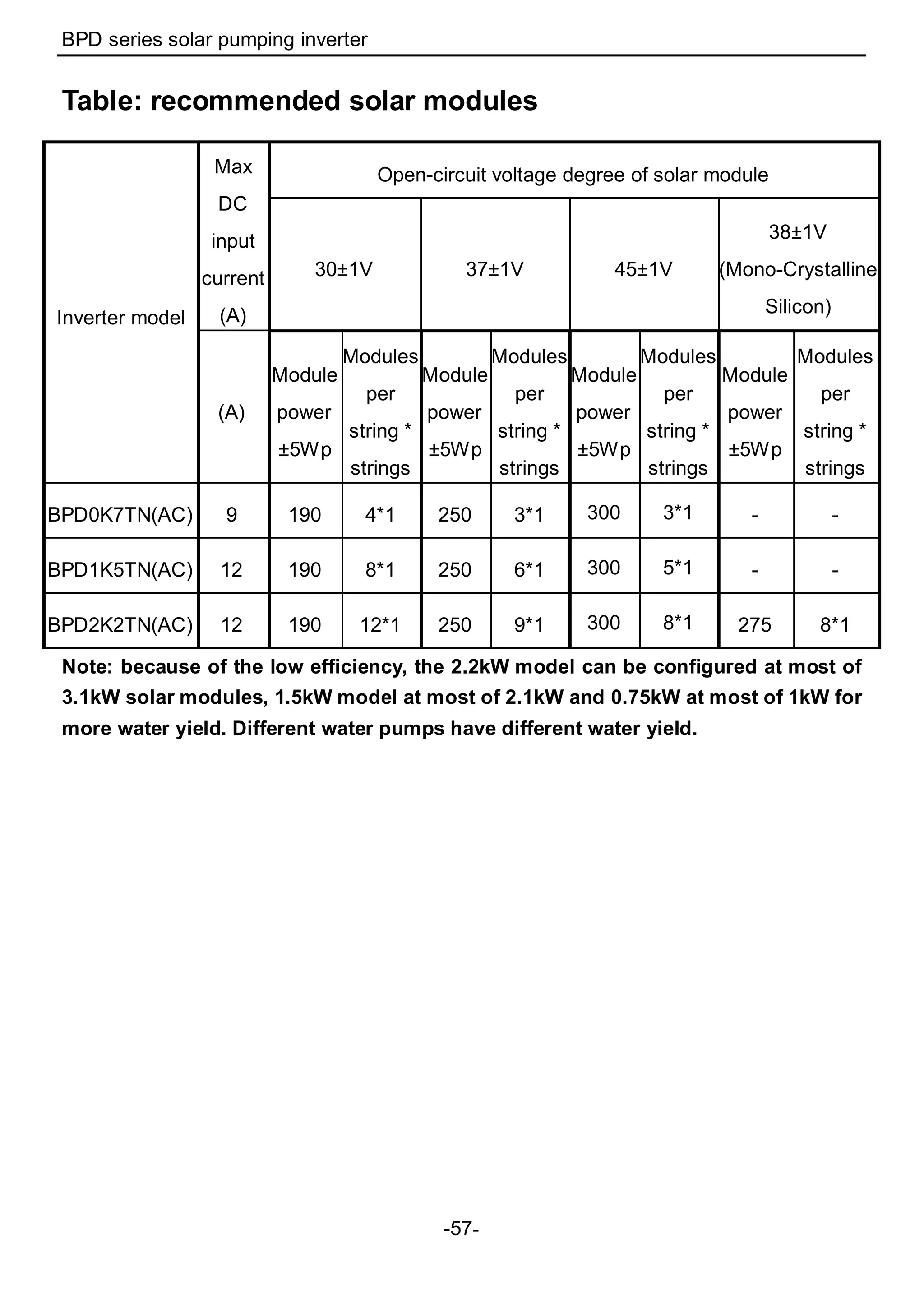

The BPD series solar pumping inverters are designed for powering water pumps using advanced control algorithms and Infineon power modules, featuring functions like maximum power tracking and various protective controls for safe operation. The document outlines crucial safety precautions, installation guidelines, product specifications, and commissioning procedures to ensure proper setup and maintenance. Additionally, it includes detailed instructions for keypad operation and troubleshooting to optimize inverter performance.


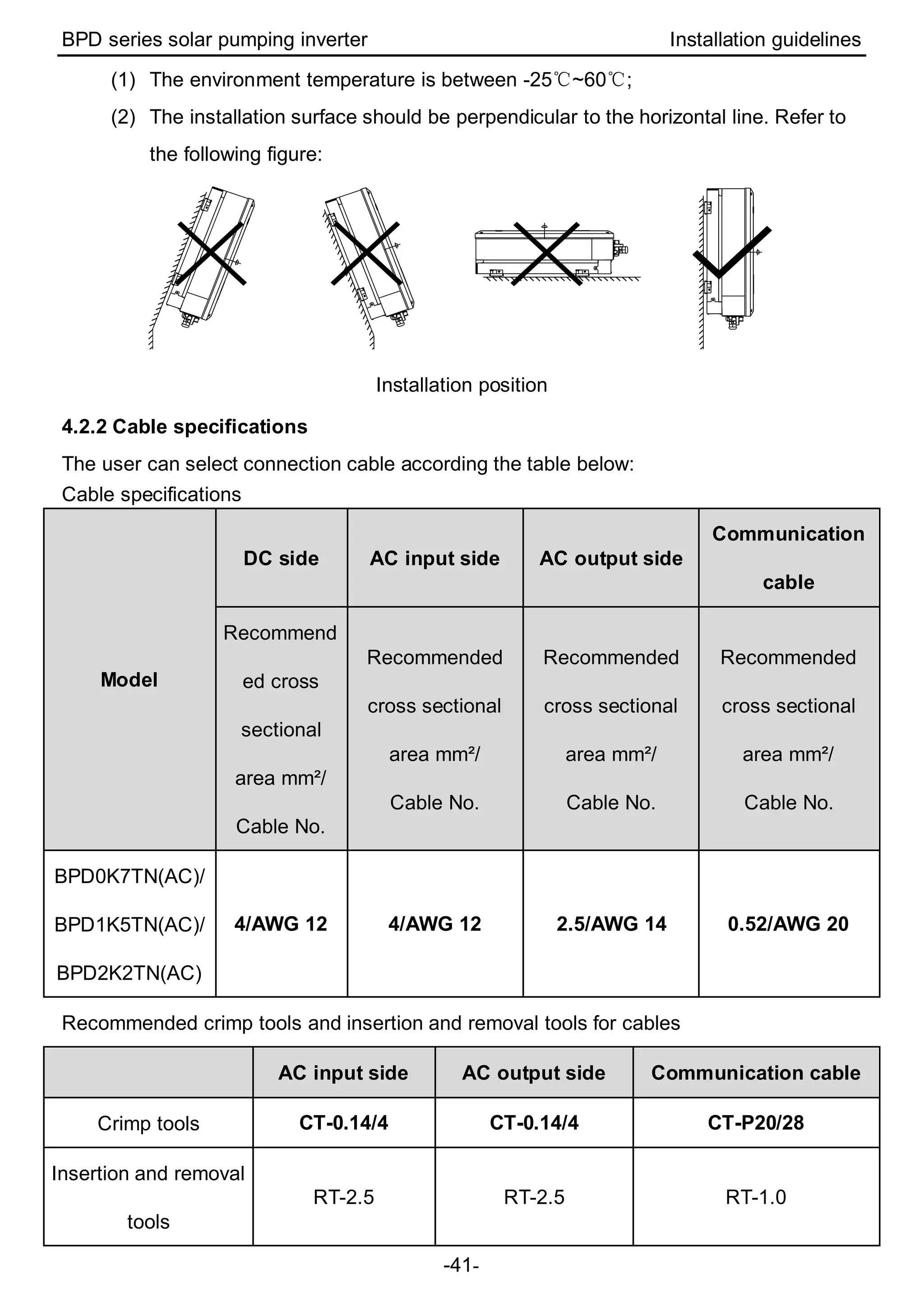
![Coded Agents – with UiPath SDK + LangGraph [Virtual Hands-on Workshop]](https://cdn.slidesharecdn.com/ss_thumbnails/codedagentsdeck-251215155422-5497c599-thumbnail.jpg?width=640&height=640&fit=bounds)


