Downloaded 22 times
![International Journal of Computer Applications Technology and Research
Volume 4– Issue 3, 192 - 196, 2015, ISSN:- 2319–8656
www.ijcat.com 192
Health Monitoring System of Elderly using Wireless
Sensor Network
Kothuru Anudeep
Dept. of ECE
Vardhaman College of Engineering
Hyderabad, India
S.Srinivas
Dept. of ECE
Vardhaman College of Engineering
Hyderabad,India
Abstract: Wireless-sensor-network-based home monitoring system for elderly activity behaviour involves functional assessment of
daily activities. In this paper, we report a mechanism for estimation of elderly well-being condition based on usage of house-hold
appliances connected through various sensing units. We define a two new wellness functions to determine the status of the elderly on
performing essential daily activities. The modernized system for monitoring and evaluating the essential daily activities was tested at
homes for four different elderly persons living alone and the results are encouraging in determining wellness of the elderly.
Keywords: Activities of daily living, elder care, home monitoring, smart home, wellness, wireless sensor network .
1. INTRODUCTION
WSN based health monitoring system for patient activities
like body temperature, heartbeat ,blood pressure etc . By the
using sensing units we can get the updates from the patient
.An intelligent home monitoring system based on ZigBee
wireless sensors network has been designed and developed to
monitor and evaluate the patient details ./Health conditions of
an elderly people can be unsafe situations during regular
works. Here is an software to get a health monitoring system
to determine patient health care system.[4]Also, the system
interprets all the essential elderly activities such as regular
activities. Basically, the system function based on the usage
data of electrical and non-electrical appliances within a home.
At the hardware level, wireless sensor network with ZigBee
[1] components are connected in the form of mesh topology,
and a central coordinator of the sensing units collect data from
the sensors connected to various appliances. In this system ,a
required number of sensors for monitoring the daily activities
of the elderly have been used. A smart sensor coordinator
collects data from the sensing units and forward to the
computer system for data processing. Collected sensor data
are of low level information containing only status of the
sensor as active or inactive and identity of the sensor. To
sense the activity behavior of elderly in real time, the next
level software module will analyze the collected data by
following an intelligent mechanism at various level of data
abstraction based on time and sequence behavior of sensor
usage.
1.1 OVER VIEW OF THE SYSTEM
1.1.1 Block diagram of Patient Section
Above block diagram representing the patient section, in that
we are continuously monitoring the patient information by
using wireless sensor networks, i.e., Temperature and heart
beat of patient. And that information we can forward to the
control room section by using Zigbee technology[1].
Figure 1. Patient Section
1.1.2 Control Section
Figure 2. Control system
From patient section we transferring the information that is
received by control room section through Zigbee and in pc it
will check and if any abnormal condition occur it will send
SMS to user by using GSM technology.
1.1.3 Medical section
Zigb
ee
Seri
al
ARM
Proce
Am
plify
hea
Temp](https://image.slidesharecdn.com/ijcatr04031005-150329105600-conversion-gate01/85/Health-Monitoring-System-of-Elderly-using-Wireless-Sensor-NetworkIjcatr04031005-1-320.jpg)
![International Journal of Computer Applications Technology and Research
Volume 4– Issue 3, 192 - 196, 2015, ISSN:- 2319–8656
www.ijcat.com 194
changes in transmitted light. The particular arrangement here
uses a wooden clothes peg to hold an infra red light emitting
diode and a matched phototransistor. The infra red filter of the
phototransistor reduces interference from fluorescent lights,
which have a large AC component in their output
The skin may be illuminated with visible (red) or infrared
LEDs using transmitted or reflected light for detection. The
very small changes in reflectivity or in transmittance caused
by the varying blood content of human tissue are almost
invisible. Various noise sources may produce disturbance
signals with amplitudes equal or even higher than the
amplitude of [5] the pulse signal. Valid pulse measurement
therefore requires extensive preprocessing of the raw signal.
The setup described here uses a red LED for transmitted light
illumination and a pin Photodiode as detector. With only
slight changes in the preamplifier circuit the same hard- and
software could be used with other illumination and detection
concepts. The detectors photo current (AC Part) is converted
to voltage and amplified by an inexpensive operational
amplifier (LM358). A PIC16F877 microcontroller converts
the analog signal with 10 bits resolution to a digital signal. An
average is calculated from 250 readings taken over a 20
milliseconds period (This equals one period of the European
power line frequency of 50 Hz).
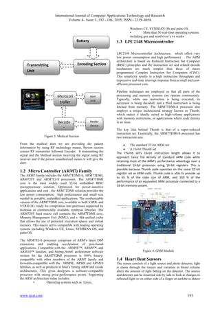
Figure 5. Heart Beat Sesnor
1.5 Temperature Sensor
The LM35 series are precision integrated-circuit temperature
sensors, whose output voltage is linearly proportional to the
Celsius (Centigrade) temperature. The LM35 thus has an
advantage over linear temperature sensors calibrated in °
Kelvin, as the user is not required to subtract a large constant
voltage from its output to obtain convenient Centigrade
scaling. The LM35 does not require any external calibration
or trimming to provide typical accuracies of ±1⁄4°C at room
temperature and ±3⁄4°C over a full −55 to +150°C
temperature range. Low cost is assured by trimming and
calibration at the wafer level. The LM35’s low output
impedance, linear output, and precise inherent calibration
make interfacing to readout or control circuitry especially
easy. It can be used with single power supplies, or with plus
and minus supplies. As it draws only 60 μA from its supply,
it has very low self-heating, less than 0.1°C in still air. The
LM35 is rated to operate over a −55° to +150°C temperature
range, while the LM35C is rated for a −40° to +110°C range
(−10° with improved accuracy). The LM35 series is available
packaged in hermetic TO-46 transistor packages, while the
LM35C, LM35CA, and LM35D are also available in the
plastic TO-92 transistor package. The LM35D is also
available in an 8-lead surface mount small outline package
and a plastic TO-220 package.
Figure 6. Temperature Sensor
2. WIRELESS COMMUNICATION
2.1 GSM Technology
To achieve important information of cars, one GSM Module
is added into the car security system. Siemens TC35I GSM
modem can quickly send SMS messages to appointed mobile
phone or SMS server [3]. So the owner and the police can be
informed at the first time. If another GPRS module is added
in, the image data could also sent to information.
A GSM modem can be an external device or a PC Card or a
PCMCIA Card. Typically, an external GSM modem is
connected to a computer through a USB cable or a
serial cable. A GSM modem in the form of a PC Card or a
PCMCIA Card is designed for a laptop computer, which
should be inserted into one of the PC Card or a PCMCIA Card
slots of a laptop computer. A GSM modem needs a SIM card
in order to operate. As mentioned in the earlier sections of the
SMS tutorial, computers use a common set of standard AT
commands to control the both the GSM and dial-up modems.
GSM modem can be used just like a dial-up modem.
Figure 7. GSM Module](https://image.slidesharecdn.com/ijcatr04031005-150329105600-conversion-gate01/85/Health-Monitoring-System-of-Elderly-using-Wireless-Sensor-NetworkIjcatr04031005-3-320.jpg)
![International Journal of Computer Applications Technology and Research
Volume 4– Issue 3, 192 - 196, 2015, ISSN:- 2319–8656
www.ijcat.com 195
2.1.1 SMS commands
AT+CIMI
Note: Read the IMSI
AT+CMGS=”+33146290800”
Note: Send a message in text mode
AT+CMGR=3
Note: Read it
AT+CMGD=3
Note: Delete it Note: Message
2.2 Zigbee Module
The Xbee/Xbee-PRO RF Modules [1] are designed to operate
within the ZigBee protocol and support the unique needs of
low-cost, low-power wireless sensor networks. The modules
require minimal power and provide reliable delivery of data
between remote devices. The modules operate within the ISM
2.4 GHz frequency band and are compatible with the
following:
XBee RS-232 Adapter
XBee RS-232 PH (Power Harvester) Adapter
XBee RS-485 Adapter
XBee Analog I/O Adapter
XBee Digital I/O Adapter
XBee Sensor Adapter
XBee USB Adapter
XStick
Connect Port X Gateways
00 XBee Wall Router.
The XBee/XBee-PRO ZB firmware release can be installed
on XBee modules. This firmware is compatible with the
ZigBee 2007 specification, while the ZNet 2.5 firmware is
based on Ember's proprietary "designed for ZigBee" mesh
stack (EmberZNet 2.5). ZB and ZNet 2.5 firmware are similar
in nature,(1) but not over-the-air compatible. Devices running
ZNet 2.5 firmware cannot talk to devices running the ZB
firmware.
Figure 8. Zigbee Section
3. MEDICAL SECTION
3.1 RF Transmitter and Receiver
Radio Frequency, any frequency within the electromagnetic
spectrum associated with radio wave propagation. When an
RF current is supplied to an antenna, an electromagnetic field
is created that then is able to propagate through space. Many
wireless technologies are based on RF field propagation Radio
Frequency: The 10 kHz to 300 GHz frequency range that can
be used for wireless communication. Also used generally to
refer to the radio signal generated by the system transmitter,
or to energy present from other sources that may be picked up
by a wireless receiver(6).
3.2 Transmitter
The TWS-434 extremely small, and are excellent for
applications requiring short-range RF remote
controls(2). The transmitter module is only 1/3 the size of a
standard postage stamp, and can easily be placed inside a
small plastic enclosure.
TWS-434: The transmitter output is up to 8mW at
433.92MHz with a range of approximately 400 foot (open
area) outdoors. Indoors, the range is approximately 200 foot,
and will go through most walls.
3.2.1.1 (c)Receiver
3.2.1.2 RWS-434: The receiver also operates at
433.92MHz, and has a sensitivity of 3uV. The WS-434
receiver operates from 4.5 to 5.5 volts-DC, and has both
linear and digital outputs.
3.2.1.3 (d)Transmitting and receiving
Full duplex or simultaneous two-way operation is not possible
with these modules. If transmit and receive module are in
close proximity and data is sent to a remote receive module(2)
while attempting to simultaneously receive data from a remote
transmit module, the receiver will be overloaded by its close
proximity transmitter. This will happen even if encoders and
decoders are used with different address settings for each
transmitter and receiver pair. If two way communications is
required, only half duplex operation is allowed.(6)](https://image.slidesharecdn.com/ijcatr04031005-150329105600-conversion-gate01/85/Health-Monitoring-System-of-Elderly-using-Wireless-Sensor-NetworkIjcatr04031005-4-320.jpg)
![International Journal of Computer Applications Technology and Research
Volume 4– Issue 3, 192 - 196, 2015, ISSN:- 2319–8656
www.ijcat.com 196
Figure 9. Screens for Medical Data Storing
4. CONCLUSION
In this time, model biotelemetry system is being implemented
into working solution. Nevertheless, there is space for
improvements in both concept and implementation details of
this system. Model biotelemetry system is currently designed
for indoor use by one patient only. More nearby instances of
inner part of model biotelemetry system managed by single
outer part of system are possible, but there exists one to one
mapping between patient and ZigBee network [1]. Future
improvements may include support for outdoor operation with
communication implemented using 3G mobile technology [3]
and patient's tracking by GPS system. With advancements in
low-power high-density FPGA solutions, FPGA
programmable system on chip technology seems to be
promising for purpose of this biotelemetry system.
5. REFERENCES
[1] Safaric S., Malaric K., “ZigBee wireless
standard”,Multimedia Signal Processing and
Communications, 48th
International Symposium
ELMAR-2006, Zadar, Croatia,June 2006.
[2] Ze Zhao and Li Cui, “EasiMed: A remote health care
solution”, Proceeding of the 2005 IEEE Engineering in
Medicine and Biology 27th Annual Conference,
Shanghai,China, September 2005.
[3] Krejcar, O., Janckulik, D., Motalova, L., Kufel, J.,
“Mobile Monitoring Stations and Web Visualization of
Biotelemetric System - Guardian II”. In EuropeComm
2009. LNICST vol. 16, pp. 284-291. R. Mehmood, et al.
(Eds). Springer, Heidelberg (2009).
[4] Krejcar, O., Janckulik, D., Motalova, L., “Complex
Biomedical System with Mobile Clients”. In The World
Congress on Medical Physics and Biomedical
Engineering 2009, WC 2009, September 07-12, 2009
Munich, Germany. IFMBE Proceedings, Vol. 25/5.
O.Dössel, W. C. Schlegel, (Eds.). Springer, Heidelberg.
(2009).
[5] Krejcar, O., Janckulik, D., Motalova, L., Frischer, R.,
“Architecture of Mobile and Desktop Stations for
Noninvasive Continuous Blood Pressure Measurement”.
In The World Congress on Medical Physics and
Biomedical Engineering 2009, WC 2009, September 07-
12, 2009 Munich, Germany. IFMBE Proceedings, Vol.
25/5. O. Dössel, W. C. Schlegel, (Eds.). Springer,
Heidelberg. (2009).
[6] Idzkowski A., Walendziuk W.: Evaluation of the static
posturograph platform accuracy, Journal of
Vibroengineering, Volume 11, Issue 3, 2009, pp.511-
516, ISSN 1392 - 8716M. Penhaker , M. Cerny, L.
Martinak, et al. HomeCare “Smart embedded
biotelemetry system” Book Series IFMBE proceedings
World Congress on Medical Physics and Biomedical
Engineering, AUG 27-SEP 01, 2006 Seoul, SOUTH
KOREA, Volume: 14 Pages: 711-714, 2007, ISSN:
1680- 0737, ISBN: 978-3-540-36839-7.](https://image.slidesharecdn.com/ijcatr04031005-150329105600-conversion-gate01/85/Health-Monitoring-System-of-Elderly-using-Wireless-Sensor-NetworkIjcatr04031005-5-320.jpg)

The document describes a wireless sensor network-based health monitoring system for elderly individuals that assesses their daily activities and well-being through connected home appliances. It outlines the use of various sensors and technologies, such as Zigbee and GSM, for tracking health indicators like temperature and heartbeat, while also incorporating a microcontroller for data processing. The system was tested with elderly participants living alone, showing promising results in monitoring their health status.


![Best Practice In Key Working[1]](https://cdn.slidesharecdn.com/ss_thumbnails/bestpracticeinkeyworking1-100128054145-phpapp02-thumbnail.jpg?width=640&height=640&fit=bounds)


![Zigbee technology [autosaved]](https://cdn.slidesharecdn.com/ss_thumbnails/zigbeetechnologyautosaved-140716030459-phpapp02-thumbnail.jpg?width=640&height=640&fit=bounds)