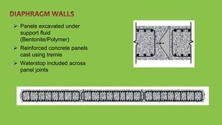
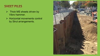
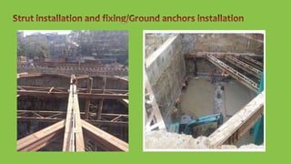
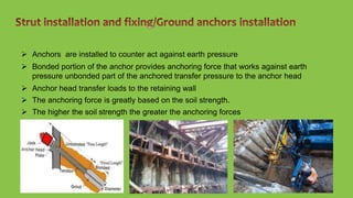
 An Excavation in soil or rock more than 15ft/4.5m is called deep excavation.
 It has some retaining system with soil/rock.
 Deep excavation employed for the construction of underground metro
stations, cut and cover tunnels, power houses, Dams and high rise
buildings.
 Deep Excavtion carried out by:
 Bottom up method
 Top down method
 Cut and cover method
1. Retaining wall construction
a. Diaphragm Walls
b. Soldier Piles
c. Secant Piles
d. Sheet Piles
2. Strut installation and fixing/Ground anchors installation
3. Dewatering
 Panels excavated under
support fluid
(Bentonite/Polymer)
 Reinforced concrete panels
cast using tremie
 Waterstop included across
panel joints
 Bored cast-in-situ piles
inserted with ISMB.
 Wooden lagging inserted
between the ISMB to control
to retain the soil.
 Horizontal movements control
by Strut arrangements.
 Bored cast-in-situ piles
alternately driven soft and
hard piles under support fluid
(Bentonite/Polymer)
 Horizontal movements control
by Strut arrangements.
 Thick MS sheets driven by
Vibro hammer.
 Horizontal movements control
by Strut arrangements.
 Placement of horizontal struts in front of retaining
structures
 Earth pressure transfer to horizontal struts through
wallers
 Center posts prevent the failure of struts due to their
own weight.
 Stage 1- Installation of Retaining walls: Retaining walls are installed before excavation commences.
Depending on site condition, soil type and excavation depth, retaining walls can be concrete walls,
concrete bored piles or steel sheet pile walls.
 Stage 2- Excavation and bracing steel strut installation: The soil is excavated to the first
strut level. The first level struts must be installed before excavation proceeds further
 While doing excavation we should maintain ground water level always 2m
below the excavation level.
 Stage 3- Excavation and bracing steel strut installation: The soil is excavated to the next strut level and
second level struts are installed. This process progresses until it reaches the final depth or formation
level. The number of strut levels depends on the excavation depth
 Anchors are installed to counter act against earth pressure
 Bonded portion of the anchor provides anchoring force that works against earth
pressure unbonded part of the anchored transfer pressure to the anchor head
 Anchor head transfer loads to the retaining wall
 The anchoring force is greatly based on the soil strength.
 The higher the soil strength the greater the anchoring forces
 Dewatering means “the separation of water from the soil,” or perhaps “taking
the water out of the particular construction problem completely.”
 There are several methods commonly used to drain or dewater a construction
site:
 Gravity flow
 Deep well Pumping
 The site is drained through
channels placed at intervals,
that permit the water to flow
away from the high points and
collecting in Sumps.
 De-watering/Submersible
pumps placed in Sumps and
water will pump out to the
Drains.
 Dewatering wells driven by
Auger boring
 Bore hole encased with slotted
casing.
 Install submersible pump inside
the casing.
 Outlet of submersible pump
connected to the drains.
 Surrounding Ground water
near the well flow through the
slotted holes.
 The collected water pump out
through the submersible pump.
Water ingress through the joints leads caving behind the
structures.
Improper Dewatering leads slush formation
Heavy floods leads surface water flow to the excavated
area.
Ground settlement surrounding locations.
Toxic gases leads Health problems.
Deep excavation

Deep excavation

  • 2.
     An Excavationin soil or rock more than 15ft/4.5m is called deep excavation.  It has some retaining system with soil/rock.  Deep excavation employed for the construction of underground metro stations, cut and cover tunnels, power houses, Dams and high rise buildings.
  • 3.
     Deep Excavtioncarried out by:  Bottom up method  Top down method  Cut and cover method 1. Retaining wall construction a. Diaphragm Walls b. Soldier Piles c. Secant Piles d. Sheet Piles 2. Strut installation and fixing/Ground anchors installation 3. Dewatering
  • 4.
     Panels excavatedunder support fluid (Bentonite/Polymer)  Reinforced concrete panels cast using tremie  Waterstop included across panel joints
  • 5.
     Bored cast-in-situpiles inserted with ISMB.  Wooden lagging inserted between the ISMB to control to retain the soil.  Horizontal movements control by Strut arrangements.
  • 6.
     Bored cast-in-situpiles alternately driven soft and hard piles under support fluid (Bentonite/Polymer)  Horizontal movements control by Strut arrangements.
  • 7.
     Thick MSsheets driven by Vibro hammer.  Horizontal movements control by Strut arrangements.
  • 8.
     Placement ofhorizontal struts in front of retaining structures  Earth pressure transfer to horizontal struts through wallers  Center posts prevent the failure of struts due to their own weight.
  • 9.
     Stage 1-Installation of Retaining walls: Retaining walls are installed before excavation commences. Depending on site condition, soil type and excavation depth, retaining walls can be concrete walls, concrete bored piles or steel sheet pile walls.
  • 10.
     Stage 2-Excavation and bracing steel strut installation: The soil is excavated to the first strut level. The first level struts must be installed before excavation proceeds further
  • 11.
     While doingexcavation we should maintain ground water level always 2m below the excavation level.  Stage 3- Excavation and bracing steel strut installation: The soil is excavated to the next strut level and second level struts are installed. This process progresses until it reaches the final depth or formation level. The number of strut levels depends on the excavation depth
  • 13.
     Anchors areinstalled to counter act against earth pressure  Bonded portion of the anchor provides anchoring force that works against earth pressure unbonded part of the anchored transfer pressure to the anchor head  Anchor head transfer loads to the retaining wall  The anchoring force is greatly based on the soil strength.  The higher the soil strength the greater the anchoring forces
  • 14.
     Dewatering means“the separation of water from the soil,” or perhaps “taking the water out of the particular construction problem completely.”  There are several methods commonly used to drain or dewater a construction site:  Gravity flow  Deep well Pumping
  • 15.
     The siteis drained through channels placed at intervals, that permit the water to flow away from the high points and collecting in Sumps.  De-watering/Submersible pumps placed in Sumps and water will pump out to the Drains.
  • 16.
     Dewatering wellsdriven by Auger boring  Bore hole encased with slotted casing.  Install submersible pump inside the casing.  Outlet of submersible pump connected to the drains.  Surrounding Ground water near the well flow through the slotted holes.  The collected water pump out through the submersible pump.
  • 17.
    Water ingress throughthe joints leads caving behind the structures. Improper Dewatering leads slush formation Heavy floods leads surface water flow to the excavated area. Ground settlement surrounding locations. Toxic gases leads Health problems.