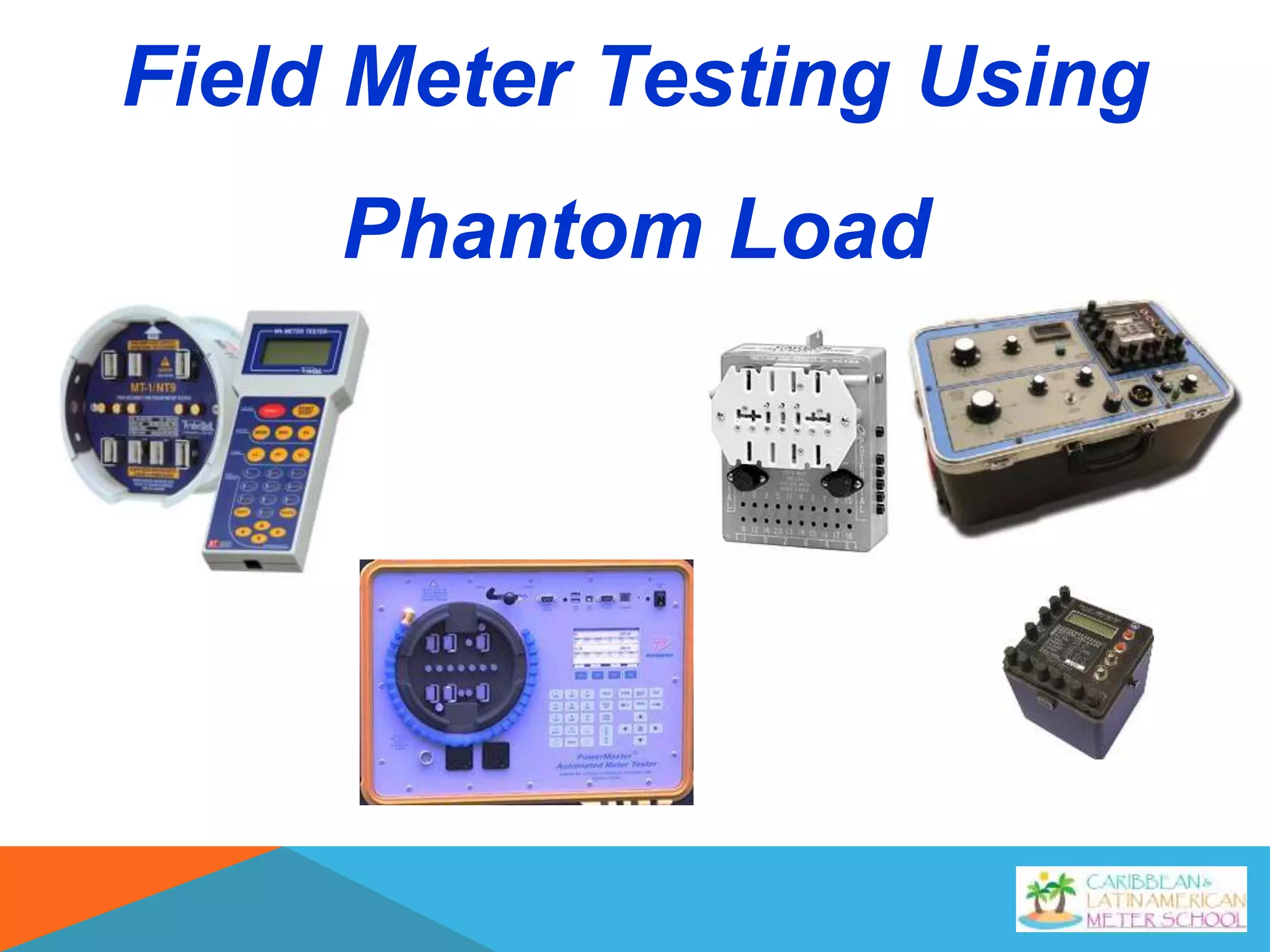
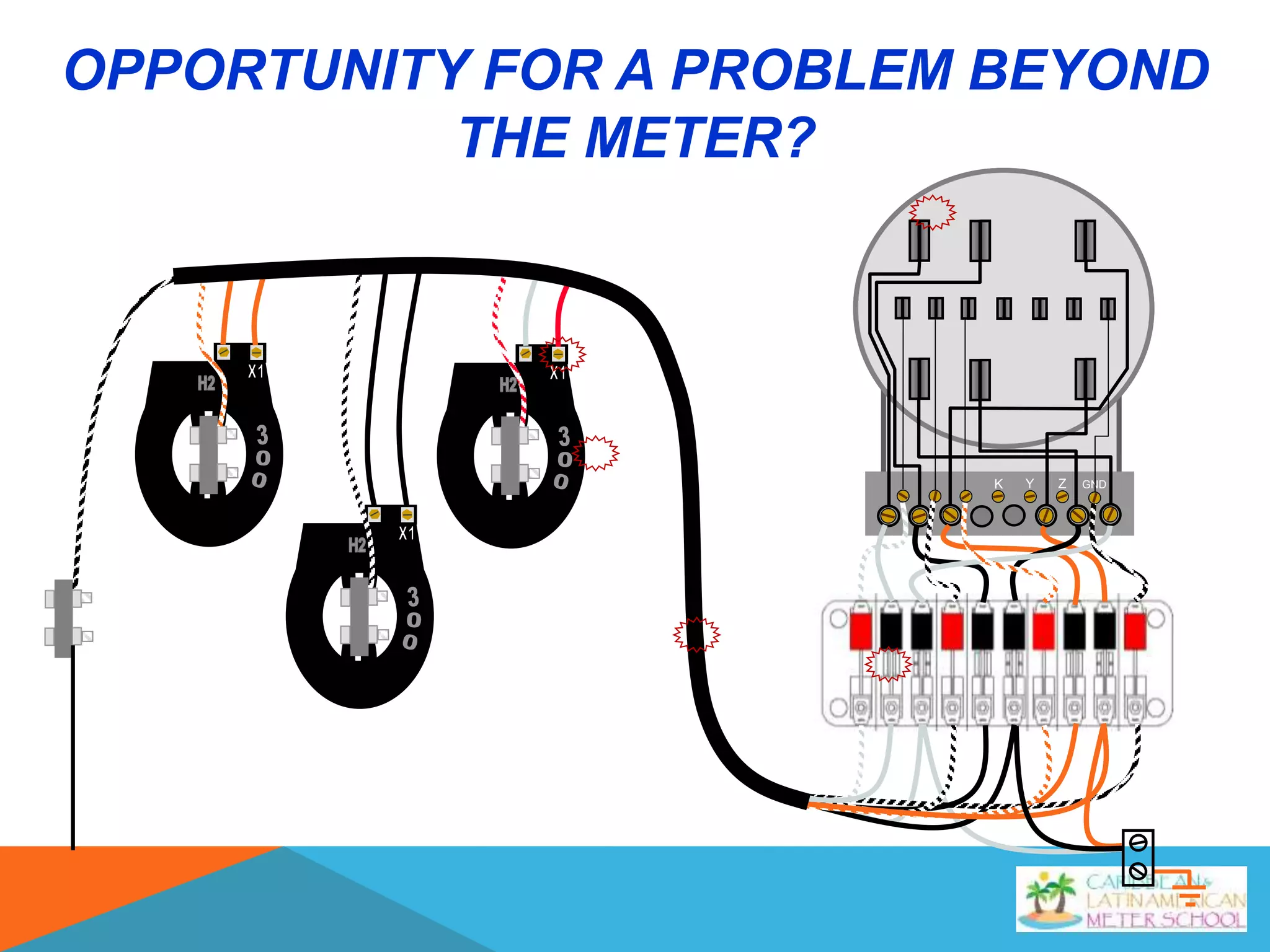
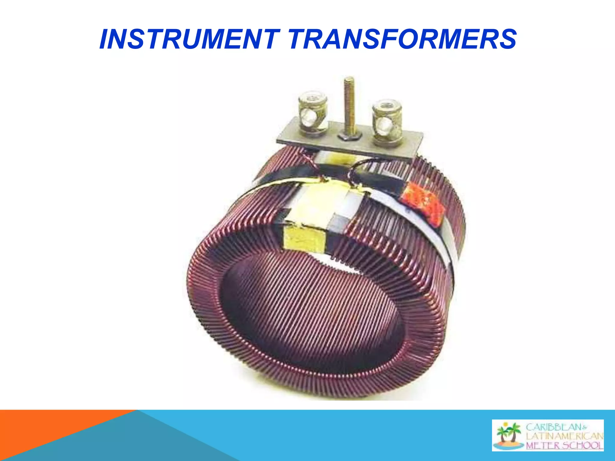
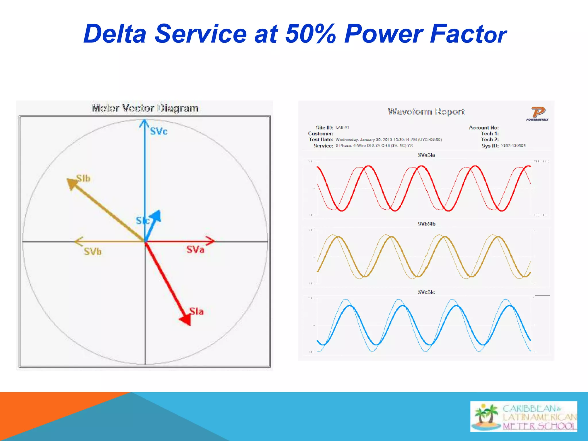
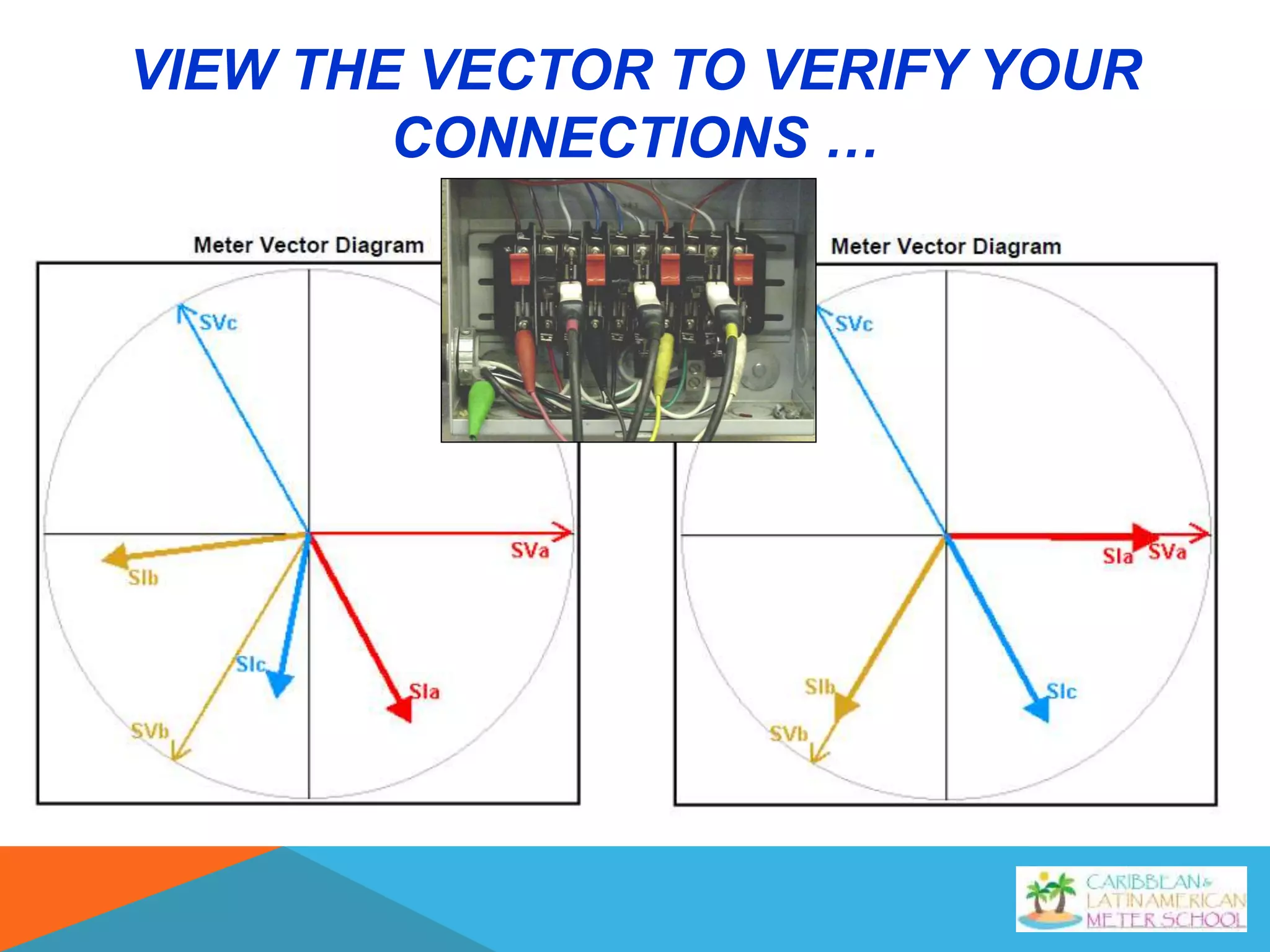
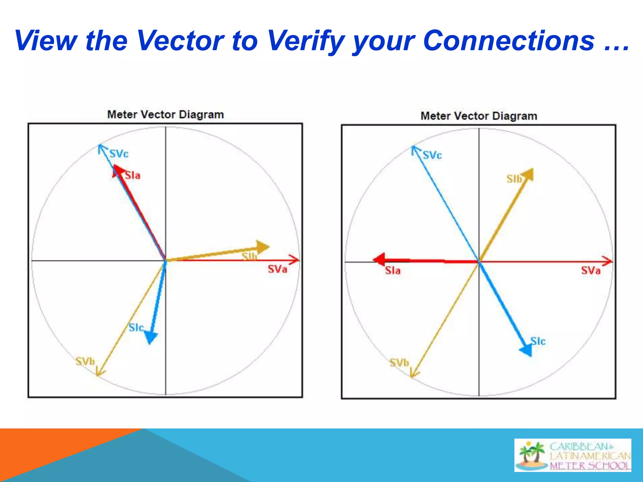
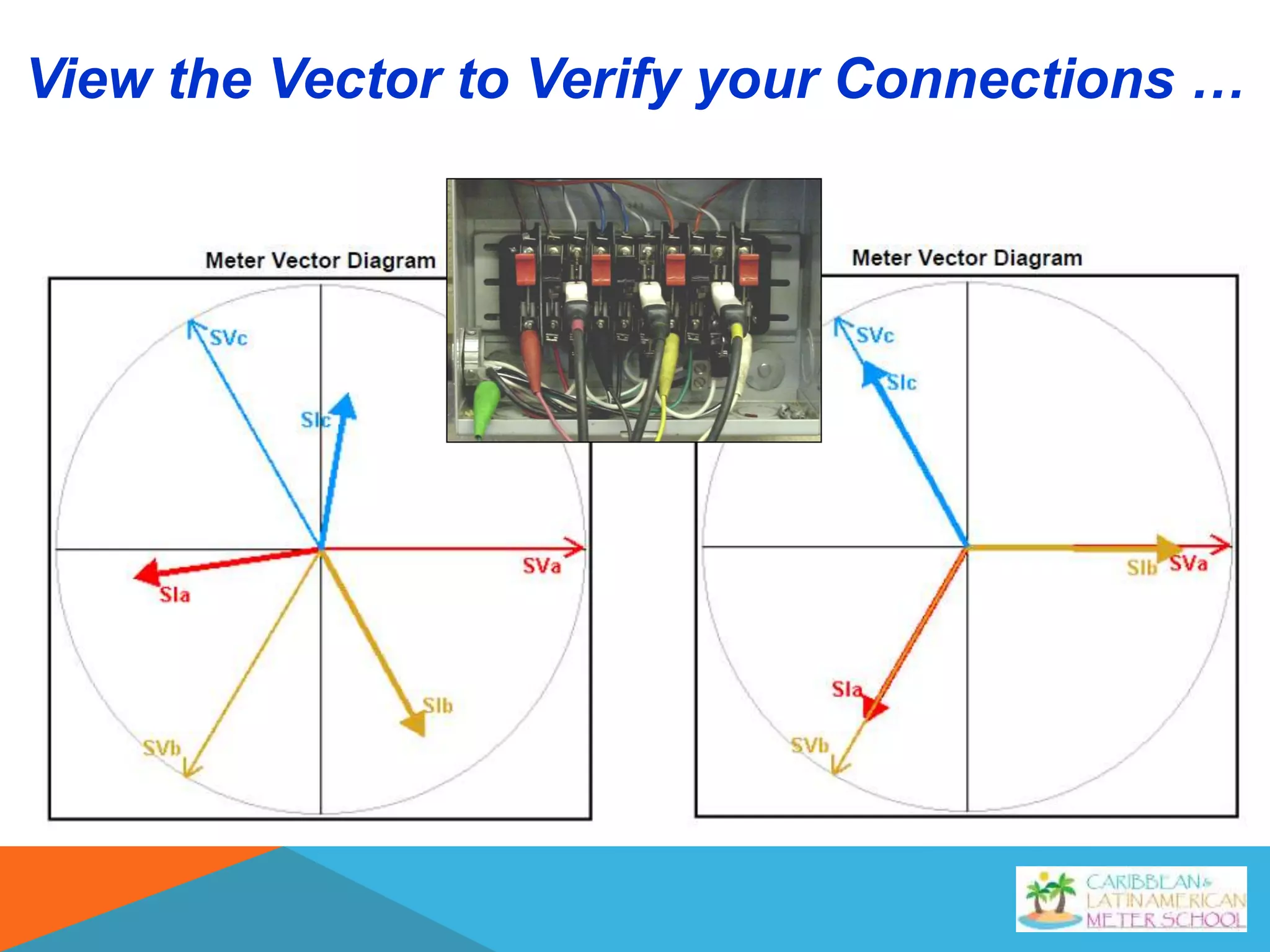
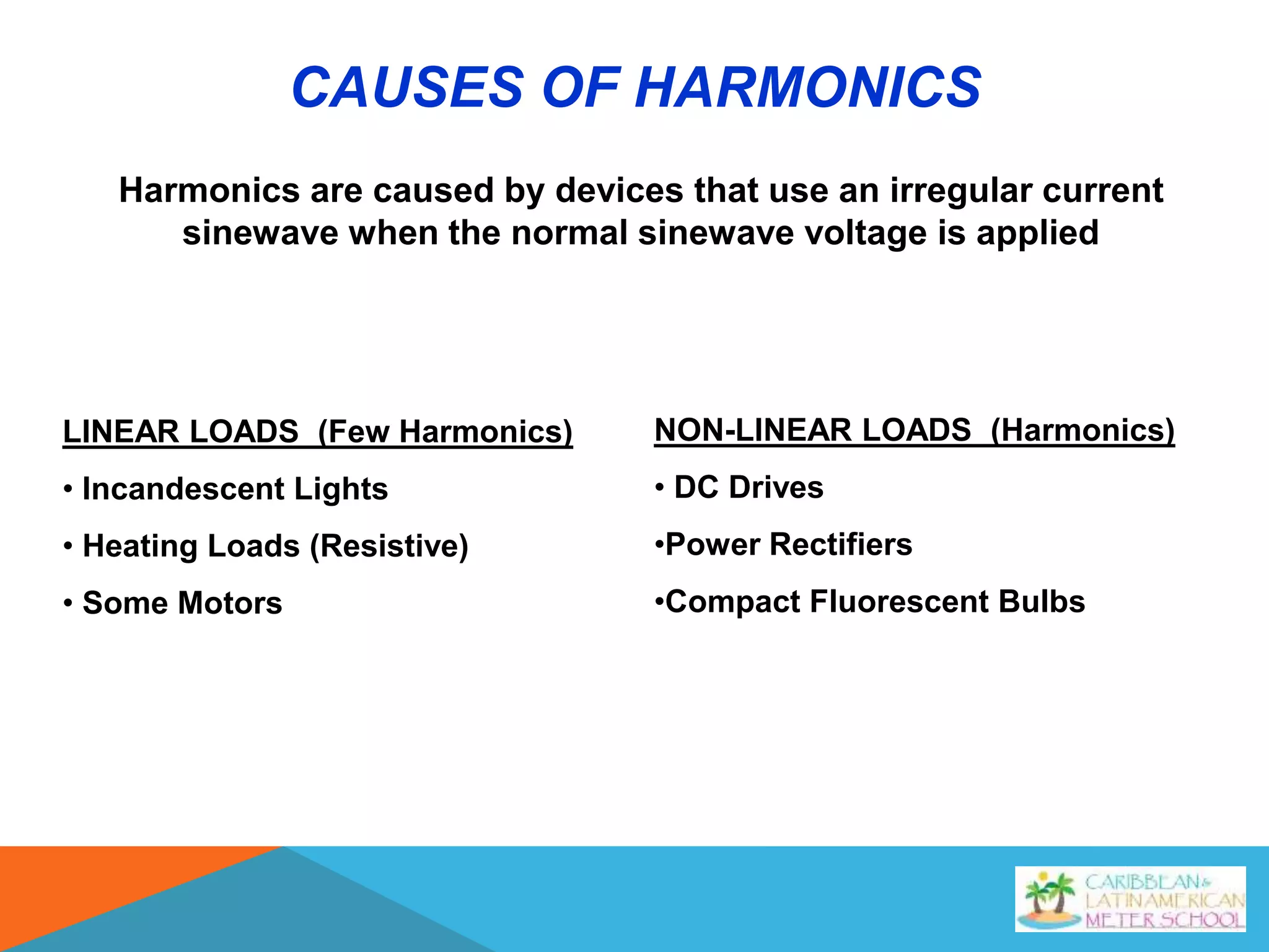
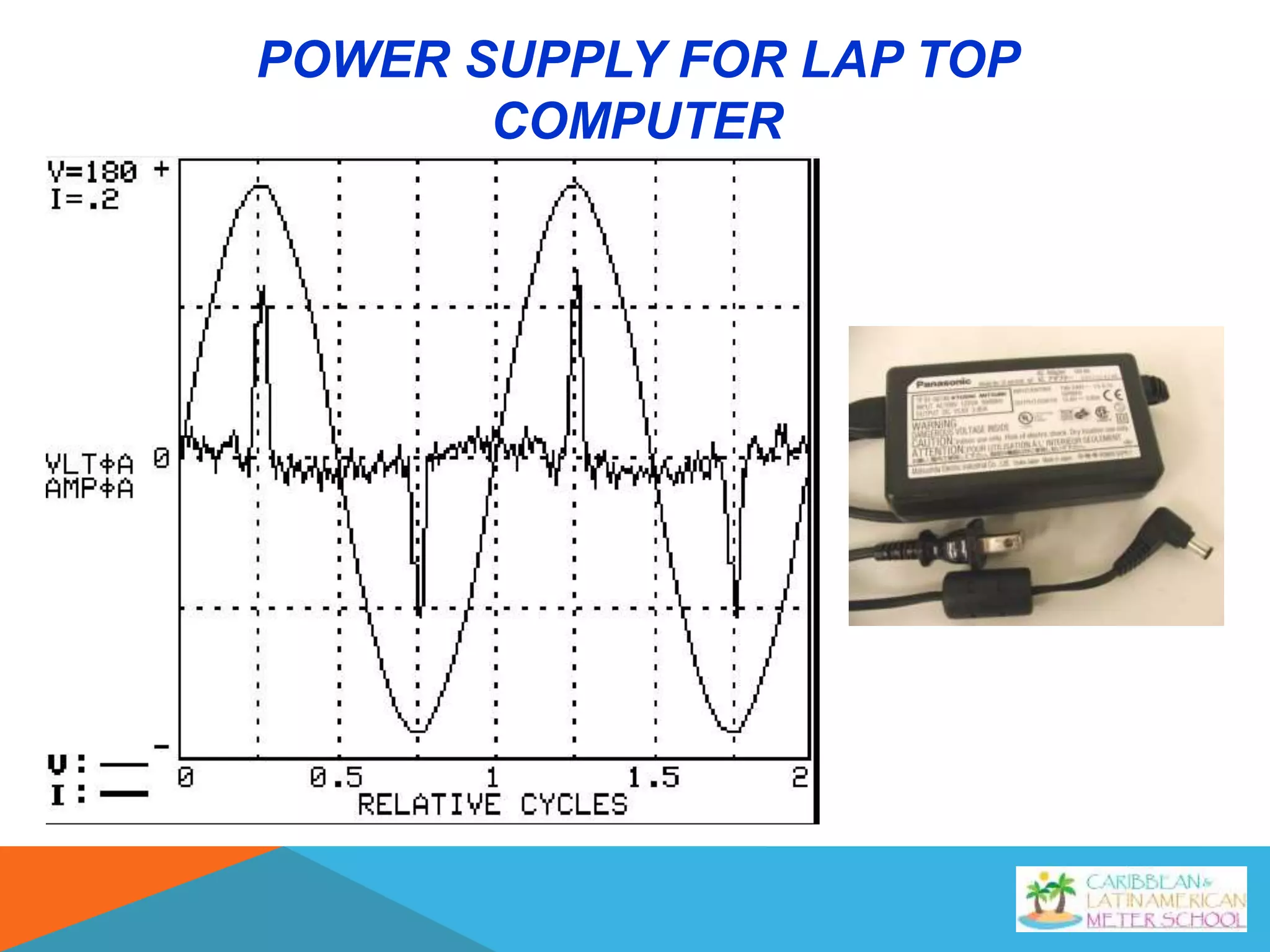
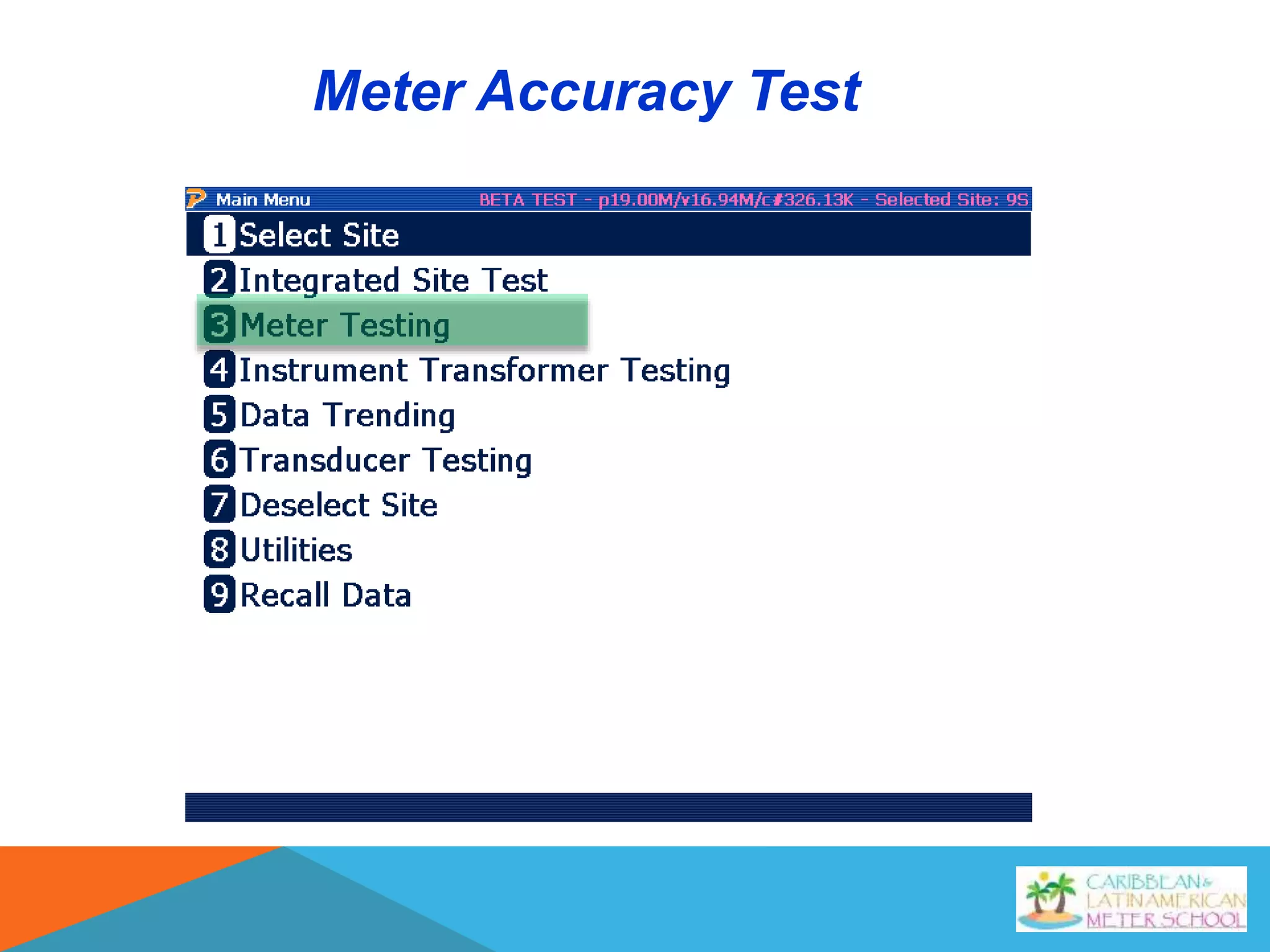
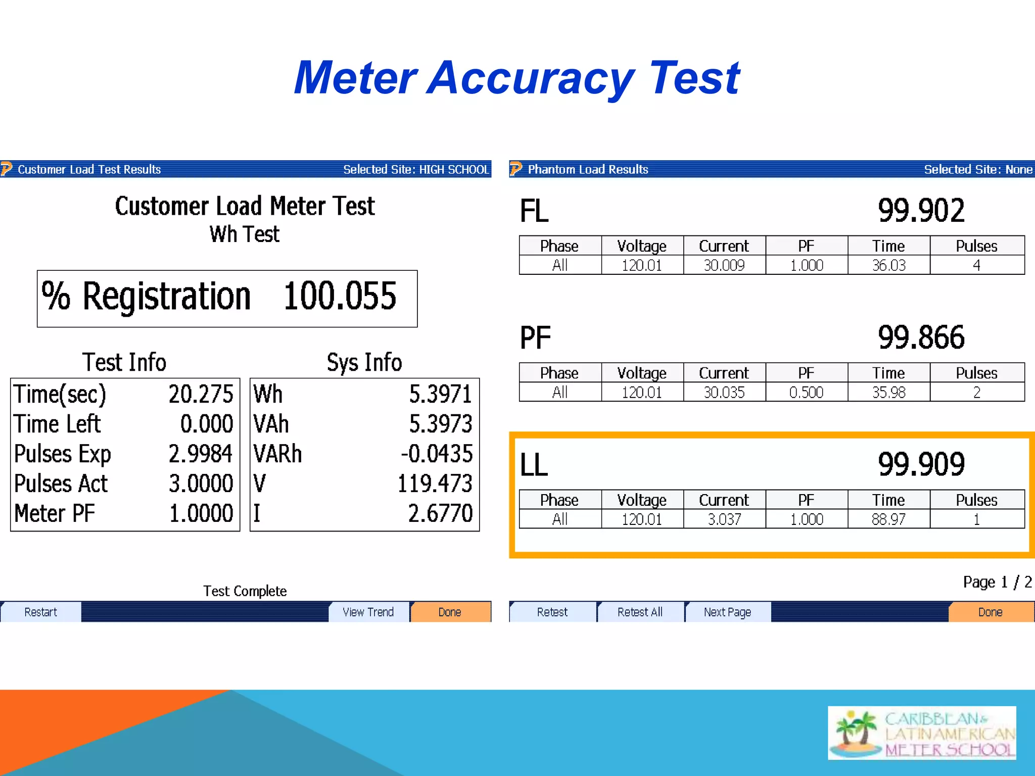
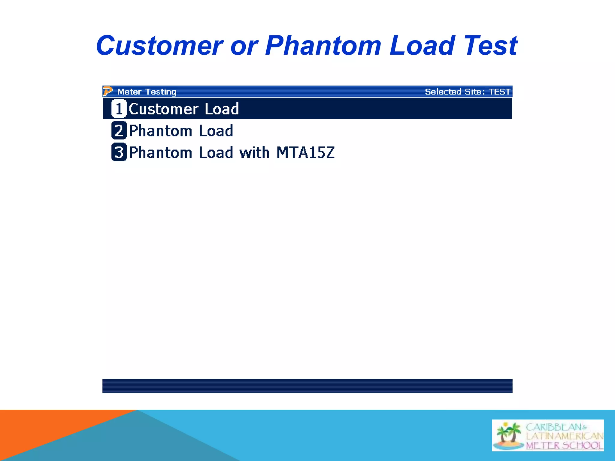
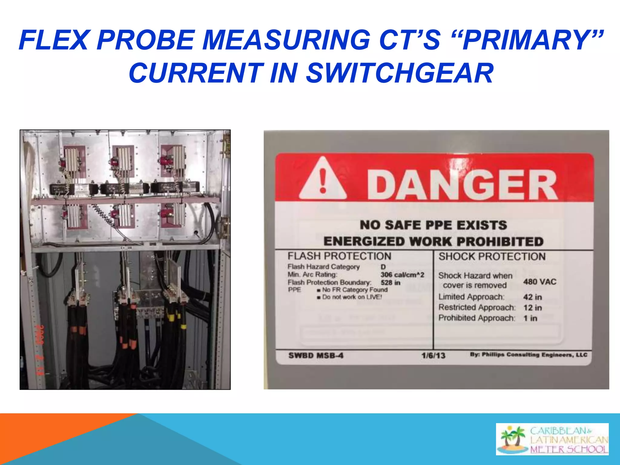
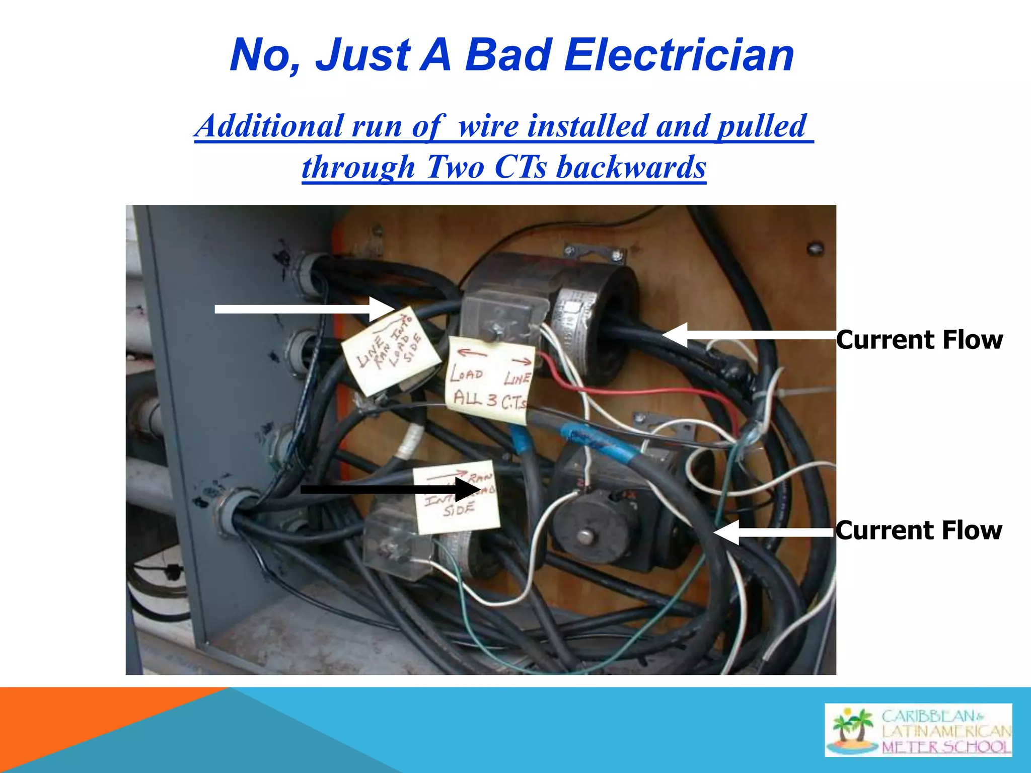
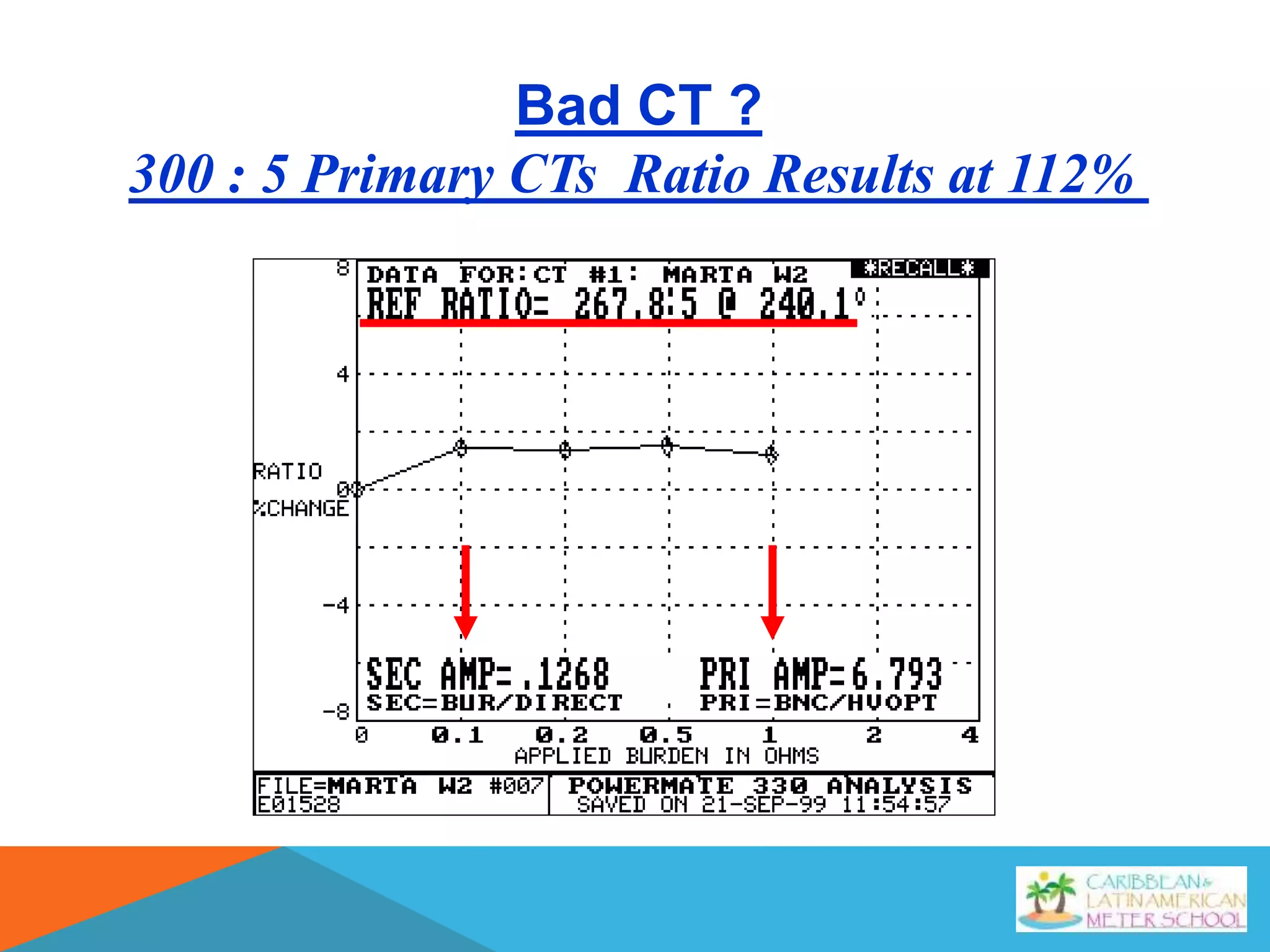
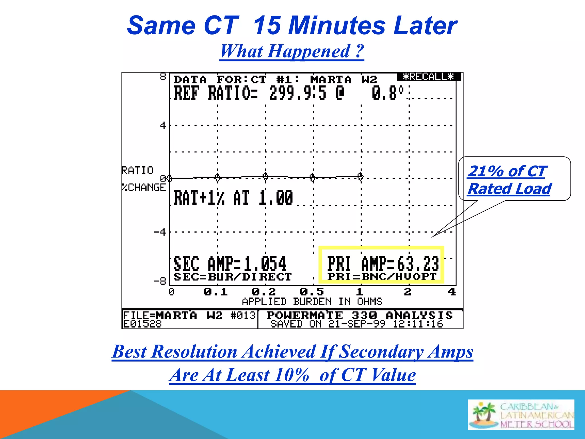
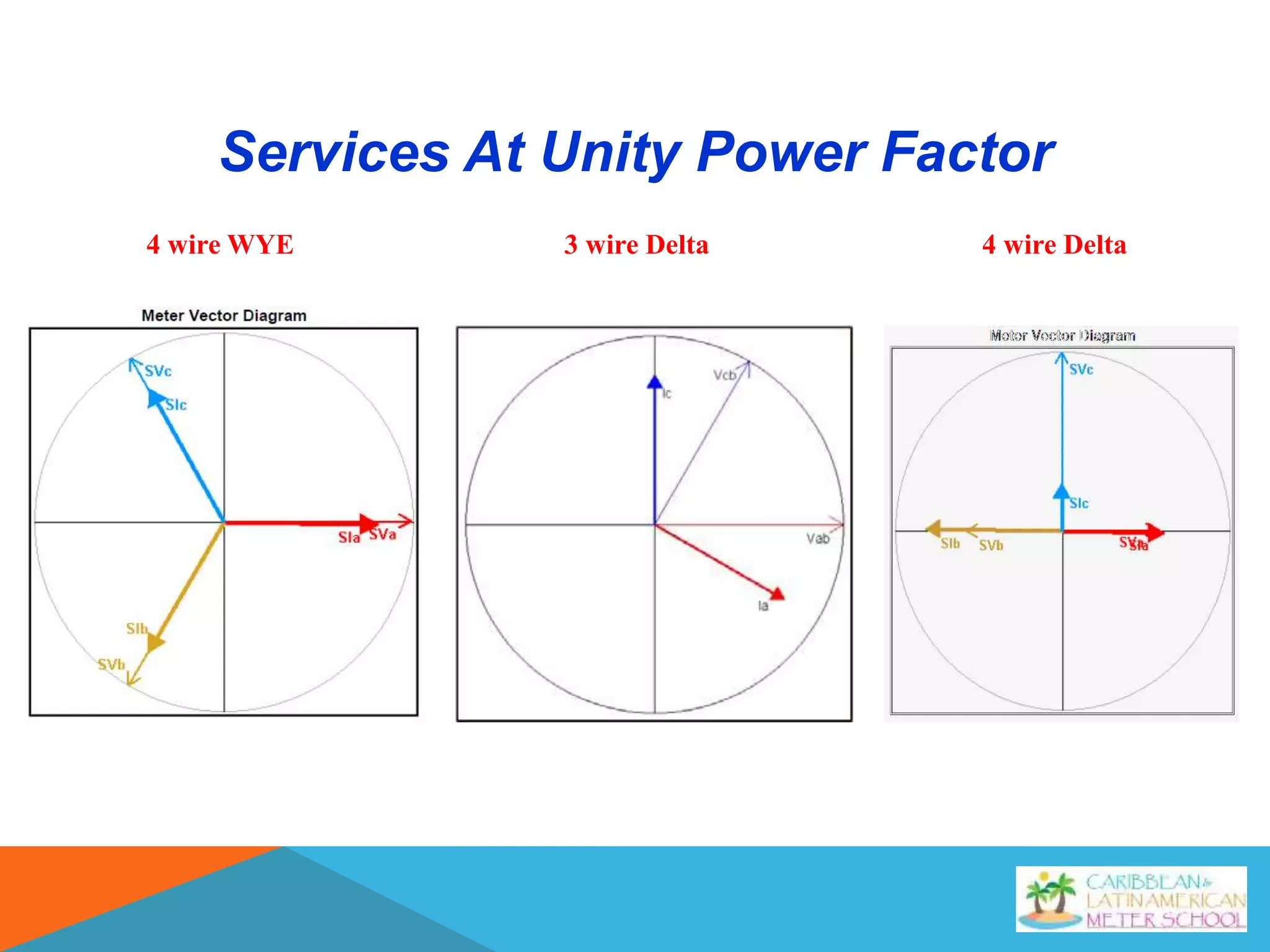
Verifying
Transformer Rated Service
Installations
January 2019
Field Meter Testing Using
Phantom Load
OPPORTUNITY FOR A PROBLEM BEYOND
THE METER?
K Y Z GNDK Y Z GND
INSTRUMENT TRANSFORMERS
CURRENT RETURN SWITCHES
C Phase Current in open
position
CURRENT RETURN SWITCHES
C Phase Current in closed position making contact with
attachment screw for shunt buss.
This re-routes current to by pass the meter.
CURRENT RETURN SWITCHES
Form 9S Abase Adaptor
Nicked Control Cable
SYSTEM ANALYZERS
PowerMetrix
PowerMaster
Spinlab
Bird Dog Plus
testMET
Gold Miner
Radian
RD31-221
SYSTEM ANALYZER WE USE
PowerMaster
5 Series Model
Testing Options Available
On the PowerMaster
Proper PPE must be
worn and all Safety
Guidelines followed.
Install the Duckbill
Current Leads
Connect the Potential
Leads making sure
they are matched to
the proper current.
Before Beginning the Integrated Site Scan
The Following Steps Must be Performed
Why ?
Select the Vector Analysis Option
Before Starting
Vector
View the Vector to Verify your Connections …
4 Wire Wye Service at Unity Power Factor
4 Wire Wye Service at 50% Power Factor
Single Phase Service
Unity 50% PF Unity
No Lag (1.00 PF) 30° Lag (0.866 PF) Waveform
Three Wire Three Phase Network Service
Three Wire Three Phase Delta Service
No Lag (1.00 PF) 30° Lag (0.866 PF)
Delta Service at Unity Power Factor
Delta Service at 50% Power Factor
VIEW THE VECTOR TO VERIFY YOUR
CONNECTIONS …
View the Vector to Verify your Connections …
Correct Vector
Potentials and Currents Match.
Start the Scan
What your Looking For!
INTEGRATED SITE TEST
Capture of Sine Waves of Amps & Volts
Capture of Vector
Captures System Overall Summary
“Breakdown Of Vector”
Harmonics for Amp And Volts
Amps Volts
Harmonics
CAUSES OF HARMONICS
Harmonics are caused by devices that use an irregular current
sinewave when the normal sinewave voltage is applied
LINEAR LOADS (Few Harmonics)
• Incandescent Lights
• Heating Loads (Resistive)
• Some Motors
NON-LINEAR LOADS (Harmonics)
• DC Drives
•Power Rectifiers
•Compact Fluorescent Bulbs
HARMONIC DISTORTION
Harmonic waveforms are simply multiples of the fundamental waveform.
The graphs below show the relationship between a fundamental (60 Hz)
current waveform and a 5th harmonic (300 Hz) component with about 25%
peak deviation.
Fundamental(60Hz)
5th Harmonic(300Hz)
ResultantWaveForm
INCANDESCENT BULB
COMPACT FLUORESCENT BULB
MOTOR
POWER SUPPLY FOR LAP TOP
COMPUTER
Meter Accuracy Test
Meter Accuracy Test
Customer or Phantom Load Test
Meter Accuracy Test Setup
Meter Test Results
kWH
Phantom Load Tests Results
VERIFYING CT ACCURACY
SETUP SCREEN FOR VERIFYING CT ACCURACY
DEVICES USED TO MEASURE THE
CT’S “PRIMARY” CURRENT
(CUSTOMER LOAD)
High Voltage Fiber Optic
Probe
Used on Primary and Overhead
Secondary Services
Flex 36 for Services 600 Volts or Less
MEASURING SECONDARY CURRENT
VERIFYING CT ACCURACY ON 600 VOLTS
OR LESS
FLEX PROBE MEASURING CT’S
“PRIMARY” CURRENT IN AN U.G.
TRANSFORMER
FLEX PROBE MEASURING CT’S “PRIMARY”
CURRENT IN SWITCHGEAR
IMPORTANT NOTE
GET AHEAD OF THE CTS…
Source Side of the CTs
WHY?
Do your best to get close to the
source as possible…
But do it SAFE!
Fiber Optic Horseshoe Probe used on
Primary Services (above 600 volts)
Fiber Optic Horseshoe Probe used on
Primary Service (above 600 volts)
Phase A
125v 1.66a
Phase B
125v 1.60a
Phase C
125v 0.00a
Fiber Optic Horseshoe Probe used on
Primary Service (above 600 volts)
Fiber Optic Horseshoe Probe can also be
used on Over Head Secondary Service
CT Ratio Test Information Results
Possible Errors will be
in RED, this appears to
be a CT running
backwards.
If you didn’t check the
vector before starting,
this is probably your
probe installed in
reverse. Check the probe
and retest the phase in
question.
CT Ratio Test Information Results
RESULTS FOR RATIO ONLY
Results for Burden Only
Should be 2000:5
Ratioed at 1432:5
Failure Began Before .1 Ohms Of
Burden Is Applied
Bad CT
Bad CT ?
Ratio Should Be 200 : 5
No, Just A Bad Electrician
Current Flow
Current Flow
Additional run of wire installed and pulled
through Two CTs backwards
Bad CT ?
300 : 5 Primary CTs Ratio Results at 112%
Best Resolution Achieved If Secondary Amps
Are At Least 10% of CT Value
Same CT 15 Minutes Later
What Happened ?
21% of CT
Rated Load
Vectors
What Do We Look For ?
Services At Unity Power Factor
4 wire WYE 4 wire Delta3 wire Delta
Typical WYE Service
Problem ?
A Phase and B Phase Current Crossed
Problem ?
CTs Wired Backwards
Three Wire Three Phase
Delta Service
Three Wire Three Phase Delta
Bad Power Factor
15° (Lag)
Normally Leading BY 30 °
Normally Laging BY 30 °
74°
Three Wire Three Phase Delta
with Worse Power Factor
Forward Rotation Stops at 90°
as the Angle Increases Reverse Rotation Begins
93°
33°
Three Wire Three Phase Delta
with Even Worse Power Factor
It looks like A-phase current is matched with B-phase
potential, and B-phase current with A-phase potential.
Problem- Crossed Potentials?
Instrumentation data from the Metercat Diagnostic Read
agreed with data reported from the AMI meter.
As the load changed, the meter would
alternate between forward energy flow and
reverse energy flow.
Problem- Crossed Potentials?
The actual problem was found to be non-brothered service conductors
through two of the current transformers. Phase-C current transformer
on the far right was correct.
C-phase CT
Measured 9.5 amps and 49.1 amps
C-phase CT
Total current measured by C-phase CT was 58.6 amps
Vectors with the same angle simply add together
Total current measured
Voltage
Current
BA C
A-phase CT
Measured 92.3 amps on B-phase and 15.4 amps on A-phase
A-phase CT
Total current measured by A-phase CT was 85.3 amps
How does 92.3 and 15.4 add up to be 85.3 ?
B-phase CT
Measured 12.5 amps on B-phase and 56.9 amps on A-phase
B-phase CT
Total current measured by A-phase CT was 47.2 amps
How does 12.5 and 56.9 add up to be 47.2 ?
Total current measured
Voltage
Current
BA C
A complex number can be visually represented as
a pair of numbers (a, b) forming a vector on a
diagram, representing the complex plane. "Re" is
the real axis, "Im" is the imaginary axis, and i is the
imaginary unit
Illustration of on-site measurements
The customer added
the 225 amp panel
some time after the
original installation.
Opportunity to Bill for Excessive Reactive Load
Metering Problem ?
Bad Power Factor
Balanced Load
WHAT CAN A CUSTOMER OR
UTILITY DO ABOUT BAD FACTOR?
?
VARs Compensator
Vars Compensator Off
Vars Compensator On
Site With VARs Compensator Installed
SAFETY
IS THE ABSOLUTE NUMBER ONE PRIORITY
Hardhat
 Eye Protection
 FR Clothing
 Rubber gloves with “Grabbit” gloves or Leather
outer protectors


Verifying Transformer Rated Service Installations