SlideShare a Scribd company logo
1 of 6
EXPERIMENT No. 6
Objective: - (i) To study universal testing machine.
Apparatus: - 1.Universal testing machine
UNIVERSAL TESTING MACHINE
Applicability and Range of Application:
Universal Testing Machine serves for conducting tests in tension, compression, bending and
shearing for metals and other materials. The testing machine is operated hydraulically. Driving is
performed by the help of an electrical motor. The machine is equipped with pendulum
dynamometer, a recording device for registering load-deformation diagram.
Description of Arrangement:
Technical Data: Measuring Ranges, Maximum Capacity 40 Tons
Construction:
The machine consists of two units viz. the loading unit A and the control panel B. shown in fig.1
The Loading Unit:
Consists of robust base (l-p1). The main hydraulic cylinder is fitted in the centre of the
base and the piston slides in the cylinder. Special materials used for the cylinder and the piston
and their careful precise machining including individual lapping have increased the accuracy of
the machine to a great extent.
A motor is fitted to the left-hand side of the base. The chain and sprocket drive by the
motor rotates two screwed columns (8-p1) mounted in the base with bearings. These screws pass
through the two main nuts (16-P4&P4) fitted in the lower cross head. Lock nuts (17-P4&P4)
avoid the loosening of the main nuts. The additional back-lash removing nuts (18-P4) are
provided to remove the back-lash screws (8p1) and the main nuts while lowering of the lower
cross-head, and avoids sudden jerk when the specimen breaks. In the long run, it can also
compensate for the wear of the screws and the nuts. The screws (I9-P4&P4) provided on the
backlash removing nut assembly are used to adjust the back-lash.
Fig.1 (P 1)
The lower table (6-P1) is connected to the main piston through a ball and ball seat joint. This
joint ensures axial loading. This lower table (6-P1) is rigidly connected to the upper cross-head
(20-P1) by two straight columns (9-P1).
The lower table and upper cross-head assembly moves up and down with the main piston. The
up and down movement of this assembly is guided by eight bearings which slide over the screw
columns. Four bearings are fitted in one bearing holder (24-P4) and two such holders are fixed
on the upper cross head with the two screwed columns (8-Pl) at their respective centre. The jaws
inserts for tensile test specimen along-with the rack jaws slide in the lower and upper cross-
heads. The sliding motion of the rack jaws is achieved by rotating the helical toothed pinion by
the operating hand wheel (22-P4&P4) provided. Jaw locking handle (2-Pl &P4) is provided to
lock the jaws of the lower cross-head after the specimen is clamped. This arrangement ensures
firm clamping of the specimen and easy take out of the broken specimen. Separate jaw pieces are
provided for different ranges of specimen diameters. Users should confirm that the correct jaw
pieces are inserted in the rack jaws before testing the specimen.
For changing the jaw pieces first take out the rack jaws. For taking out the rack jaws, remove the
top plate (21-P1&P4) from the top of the upper cross-head. Now rotate the pinion and take out
the rack jaws by hand from the top. For taking out the jaws from lower cross-head, lock the
handle and take out the lower plate (12-P1) from the bottom. The jaws will come out from
bottom if you release the handle slowly by un-locking. Take care that the jaws do not fall down
on the lower table. After taking out. the rack jaws, removed the clamping strips from the rack
jaws, which are screwed to it. Now insert the correct jaw pieces and fix the clamping strips in
their position. The jaw pieces must be inserted in the direction of the arrow marked on it.
Insert the lower rack jaws from the bottom of the lower cross-head. Care should be taken that
both the jaws are inserted at .a time and their top faces come in the same plane when those are
taken up to touch each other. Rotate the handle, take up the jaws in the chuck and confirm the
piston of the rack jaws. Lock the operation handle in its uppermost piston.
Then fix up the lower plate (12-P 1), similarly insert the upper jaws ham the top of the upper
cross head and fix up the top plate (21-P 1).
Note: The jaws should always be released slowly.
The upper and lower jaws are non-interchangeable.
Two compression plates viz, upper (11-P1) and lower (7-P1) are provided for conducting
compression test. The lower compression plate (7-P1) is to be kept on the lower table (6-P1) in
the location hole provided and the upper compression plate (11-P1) is to be clamped to the
bottom of the lower cross head. For clamping this plate, take the jaws in the lower cross head to
their bottom most position (no head of removal) - keep the top plate (3-P1) on the top lower
cross-head, place in such a position that its projected portion fits correctly in the chuck bolt,
resulting in the correct position of the control hole. Now insert the clamp stud from the top
through the hole of the top plate. The clamp stud will come out from the centre hole of the lower
plate (12-P1). Now screw the upper compression plate (II-PI) to the clamp stud and tighten it
against the lower plate (12-P1) by the nut (15P1&P4) from above.
The space between the lower table and the lower cross head is used from compression, bend and
shear tests, and the space between the lower and upper cross heads is used for tension test. In any
test, the up and down motion of the lower table and upper cross-head assemble performs the
loading action. The mechanical up and down motion of the lower cross-head (10-P1) is provided
for rapid initial space adjustment depending on the length or height of the tension and
compression test specimen respectively.
Bending table (25-P4), Bending Rollers (28-P4) and bending pan (29-P2) are provided as an
attachment for carrying out bend test.
An elongation scale (30-P4) is kept sliding on the scale rod (31-P4) which is fixed between the
lower table and the upper cross-head. Elongation indicating pointer (32-P4) is fixed to the lower
cross-head. The scale can slide on the rod when the screw at its back is loosened and can be set
to indicate zero before starting the loading on the specimen. Limit switch x 4 provided below the
lower table for limiting the maximum stroke of the piston.
The Control Panel:
The main units in the control panel are:-
The oil tank (33-P2) which contains the hydraulic oil level sight class (34-P2) for checking the
oil level is fitted to the oil tank. The fitted to the oil tank cover (35-P2) filtrs the incoming oil, to
the tank. Drain cock (36-P2) is provided to take out the oil while cleaning the tank.
The pump is a positive displacement type pump. This assures continuous high non-pulsating oil
current for the smooth application of the load on the specimen. The pump is fitted to the tank
cover (35-P2) from bottom which makes it easily assessable. The electric motor is fitted on the
plate hinged at the bottom (38-P2). Belt tightening or loosening can be achieved very easily as
shown in the fig and the motor can be locked at the desired position by the check nuts.
Two valves on the control panel, one at the right side and the other at the left side are used to
control the oil flow in the hydraulic systems. The right side valve (39-P2&P2) is a pressure
compensated flow control valve. The overload relief valve is adjusted and is locked.
The left side valve (4-P2) is a return valve. This valve allows the oil from the cylinder to go back
to the tank, there-by reducing the pressure in the cylinder and then the working piston comes
down. The rate of oil returns and so the speed of piston return can be adjusted by this valve. If
the return valve is closed, oil delivered by the pump passes through the flow control valve (39-
P2) (if in open position) to the cylinder and the piston goes up. If it comes across any resistance
(i.e. resistance of any test piece), pressure starts developing until either the specimen break of the
load reaches the maximum value of the range adjusted. Pressure compensation of the flow
control is an unique design which keeps a constant rate of straining regardless of the total load on
the specimen and you need not adjust the control knob again and again if it is once adjusted for a
particular rate of straining. High pressure oil connection is given from the valve (39-P2) to the
cylinder at its centre. This high pressure oil supplied at the cylinder centre serves as a" hydraulic
bearing for the piston and reduces the friction, thereby increasing the accuracy. It also helps in
getting the pressure compensation effect.
Fig. 2 (P2)
The confine control valve (41-P2) is specially provided and set by the manufacturer so as to
control the rate of loading very precisely by means of the right control valve only. So the
adjustment of the needle valve is not to be disturbed by the users. .
The needle valve (45-P2) is a damper speed control valve. It controls the return peed of the
pendulum when the specimen breaks and the pendulum tries to come down suddenly due to
sudden pressure drop in the main cylinder. It obstructs to the return flow of the oil and thus
avoids sudden jerks to the dynamometer piston and the indicating mechanism.
Dynamometer is a unit which measures and indicates the load on the specimen. The overall
accuracy of the machine depends mainly on the accuracy of this unit. It is a pendulum
dynamometer consisting of a cylinder in which the piston reciprocates. The cylinder top is
connected to the main hydraulic cylinder. So the oil pressure under the work pi ton is transmitted
to the small measuring piston in the dynamometer. The displacement of the measuring piston
causes the pendulum to deflect as far as the equilibrium point. This deflection represents the
measurement of the load on the specimen. The deflection is registered by a pointer on a dial. The
pendulum weight is subdivided into several detachable weight discs. Thus various measuring
ranges, from full load up to 1/10 of the full load can be obtained. The dynamometer piston is
kept rotating at a slow speed. The drive is taken from the same motor (38-P2) driving the pump
with worm wheel reduction (14-P2) in between the rotating piston assures dynamic friction
conditions and increases the measuring accuracy. The dynamometer is also equipped with an
integral check valve. When the specimen breaks, this valve avoids the return oil flow from the
measuring cylinder and the oil has to bypass through the damper control valve (45-P2) getting
the damping effect. In addition to the accurate load indication on the scale a recording instrument
automatically registers the load elongation diagram. A pen (43-P1) fixed to pen holder (44-P1)
which is fixed to the main rack, moves across the recording drum (42-P1) as the load increases.
At the same time the drum is rotated through small gears by taking movement of the lower table.
The movement of the lower table is taken through chain and sprockets without slip and friction
as the specimen under test is elongated. Thus an automatic graph of load against elongation is
plotted. A big size load indicating dial (46-Pl), fitted with a glass cover (47-Pl) is mounted at the
front side of the control panel. The range indicating dial, located at the back side of the load
indicating dial is to be adjusted for the particular range selected. A range adjuster knob (48-P1) is
provided for this adjustment. A zero adjusting knob (l3-Pl) provided at the right hand side serves
for initial zero adjustment.

More Related Content

What's hot

Compressive Strength of Hydraulic Cement Mortar | Jameel Academy
Compressive Strength of Hydraulic Cement Mortar | Jameel AcademyCompressive Strength of Hydraulic Cement Mortar | Jameel Academy
Compressive Strength of Hydraulic Cement Mortar | Jameel AcademyJameel Academy
 
Specific Speed of Turbine | Fluid Mechanics
Specific Speed of Turbine | Fluid MechanicsSpecific Speed of Turbine | Fluid Mechanics
Specific Speed of Turbine | Fluid MechanicsSatish Taji
 
Strength of materials_I
Strength of materials_IStrength of materials_I
Strength of materials_IPralhad Kore
 
Centrifugal Pumps Different Parts & Their function in Pharmaceuticals Indust...
Centrifugal Pumps Different Parts  & Their function in Pharmaceuticals Indust...Centrifugal Pumps Different Parts  & Their function in Pharmaceuticals Indust...
Centrifugal Pumps Different Parts & Their function in Pharmaceuticals Indust...harish pandey
 
Design of machine elements - DESIGN FOR SIMPLE STRESSES
Design of machine elements - DESIGN FOR SIMPLE STRESSESDesign of machine elements - DESIGN FOR SIMPLE STRESSES
Design of machine elements - DESIGN FOR SIMPLE STRESSESAkram Hossain
 
Unit 1 what is machine design
Unit 1 what is machine designUnit 1 what is machine design
Unit 1 what is machine designSomnath Kolgiri
 
Hydro electric power plant
Hydro electric power plantHydro electric power plant
Hydro electric power plantYuri Melliza
 
Design recomendation for storage tank
Design recomendation for storage tankDesign recomendation for storage tank
Design recomendation for storage tankDadan Yupi Andika
 
Lecture 13 torsion in solid and hollow shafts 1
Lecture 13 torsion in solid and hollow shafts 1Lecture 13 torsion in solid and hollow shafts 1
Lecture 13 torsion in solid and hollow shafts 1Deepak Agarwal
 
design of pressure vessel (thick and thin cylinders) may 2020
design of pressure vessel (thick and thin cylinders) may 2020design of pressure vessel (thick and thin cylinders) may 2020
design of pressure vessel (thick and thin cylinders) may 2020Gaurav Mistry
 
Applied Hydraulics Module 3 Impact of Jets
Applied Hydraulics Module 3 Impact of JetsApplied Hydraulics Module 3 Impact of Jets
Applied Hydraulics Module 3 Impact of Jetsnirannjan344
 
Universal testing machines
Universal testing machinesUniversal testing machines
Universal testing machinesGulfam Hussain
 
Fluid Mechanics and Turbo Design ch2
Fluid Mechanics and Turbo Design ch2Fluid Mechanics and Turbo Design ch2
Fluid Mechanics and Turbo Design ch2danielmabengo
 

What's hot (20)

UTM
UTMUTM
UTM
 
Compressive Strength of Hydraulic Cement Mortar | Jameel Academy
Compressive Strength of Hydraulic Cement Mortar | Jameel AcademyCompressive Strength of Hydraulic Cement Mortar | Jameel Academy
Compressive Strength of Hydraulic Cement Mortar | Jameel Academy
 
Specific Speed of Turbine | Fluid Mechanics
Specific Speed of Turbine | Fluid MechanicsSpecific Speed of Turbine | Fluid Mechanics
Specific Speed of Turbine | Fluid Mechanics
 
Strength of materials_I
Strength of materials_IStrength of materials_I
Strength of materials_I
 
Centrifugal Pumps Different Parts & Their function in Pharmaceuticals Indust...
Centrifugal Pumps Different Parts  & Their function in Pharmaceuticals Indust...Centrifugal Pumps Different Parts  & Their function in Pharmaceuticals Indust...
Centrifugal Pumps Different Parts & Their function in Pharmaceuticals Indust...
 
Design of machine elements - DESIGN FOR SIMPLE STRESSES
Design of machine elements - DESIGN FOR SIMPLE STRESSESDesign of machine elements - DESIGN FOR SIMPLE STRESSES
Design of machine elements - DESIGN FOR SIMPLE STRESSES
 
Unit 1 what is machine design
Unit 1 what is machine designUnit 1 what is machine design
Unit 1 what is machine design
 
Hydro electric power plant
Hydro electric power plantHydro electric power plant
Hydro electric power plant
 
Design recomendation for storage tank
Design recomendation for storage tankDesign recomendation for storage tank
Design recomendation for storage tank
 
Welded joints
Welded jointsWelded joints
Welded joints
 
Deflection
DeflectionDeflection
Deflection
 
Lecture 13 torsion in solid and hollow shafts 1
Lecture 13 torsion in solid and hollow shafts 1Lecture 13 torsion in solid and hollow shafts 1
Lecture 13 torsion in solid and hollow shafts 1
 
design of pressure vessel (thick and thin cylinders) may 2020
design of pressure vessel (thick and thin cylinders) may 2020design of pressure vessel (thick and thin cylinders) may 2020
design of pressure vessel (thick and thin cylinders) may 2020
 
Shear stresses in beams
Shear stresses in beamsShear stresses in beams
Shear stresses in beams
 
Applied Hydraulics Module 3 Impact of Jets
Applied Hydraulics Module 3 Impact of JetsApplied Hydraulics Module 3 Impact of Jets
Applied Hydraulics Module 3 Impact of Jets
 
trusses
trussestrusses
trusses
 
Universal testing machines
Universal testing machinesUniversal testing machines
Universal testing machines
 
Impact of Free Jets
Impact of Free JetsImpact of Free Jets
Impact of Free Jets
 
Fluid Mechanics and Turbo Design ch2
Fluid Mechanics and Turbo Design ch2Fluid Mechanics and Turbo Design ch2
Fluid Mechanics and Turbo Design ch2
 
Thin cylinder
Thin cylinderThin cylinder
Thin cylinder
 

Viewers also liked

Universal Coupling Experiment
Universal Coupling ExperimentUniversal Coupling Experiment
Universal Coupling ExperimentBlack Kaizen
 
Universal joint and intermittent motion mechanism
Universal joint and intermittent motion mechanism Universal joint and intermittent motion mechanism
Universal joint and intermittent motion mechanism MichaelAzada
 
DESIGN ANALYSIS OF UNIVERSAL JOINT SHAFT FOR ROLLING MILLS
DESIGN ANALYSIS OF UNIVERSAL JOINT SHAFT FOR ROLLING MILLSDESIGN ANALYSIS OF UNIVERSAL JOINT SHAFT FOR ROLLING MILLS
DESIGN ANALYSIS OF UNIVERSAL JOINT SHAFT FOR ROLLING MILLSSughosh Deshmukh
 
Universal testing machines
Universal testing machinesUniversal testing machines
Universal testing machinesShivam Tiwari
 
Some basics of Strength Of Materials..
Some basics of Strength Of Materials..Some basics of Strength Of Materials..
Some basics of Strength Of Materials..Mohammed Mubeen
 

Viewers also liked (6)

Universal Coupling Experiment
Universal Coupling ExperimentUniversal Coupling Experiment
Universal Coupling Experiment
 
Universal joint and intermittent motion mechanism
Universal joint and intermittent motion mechanism Universal joint and intermittent motion mechanism
Universal joint and intermittent motion mechanism
 
Universal joints
Universal jointsUniversal joints
Universal joints
 
DESIGN ANALYSIS OF UNIVERSAL JOINT SHAFT FOR ROLLING MILLS
DESIGN ANALYSIS OF UNIVERSAL JOINT SHAFT FOR ROLLING MILLSDESIGN ANALYSIS OF UNIVERSAL JOINT SHAFT FOR ROLLING MILLS
DESIGN ANALYSIS OF UNIVERSAL JOINT SHAFT FOR ROLLING MILLS
 
Universal testing machines
Universal testing machinesUniversal testing machines
Universal testing machines
 
Some basics of Strength Of Materials..
Some basics of Strength Of Materials..Some basics of Strength Of Materials..
Some basics of Strength Of Materials..
 

Similar to Utm theory

sunflower pump v 1.2
sunflower pump v 1.2sunflower pump v 1.2
sunflower pump v 1.2Taylor Hayek
 
Renr8305 renr8305 02-sis
Renr8305 renr8305 02-sisRenr8305 renr8305 02-sis
Renr8305 renr8305 02-sisafrodita123
 
Hyundai hsl650 7 skid steer loader service repair manual
Hyundai hsl650 7 skid steer loader service repair manualHyundai hsl650 7 skid steer loader service repair manual
Hyundai hsl650 7 skid steer loader service repair manualfjjsekdmme
 
Hyundai hsl650 7 skid steer loader service repair manual
Hyundai hsl650 7 skid steer loader service repair manualHyundai hsl650 7 skid steer loader service repair manual
Hyundai hsl650 7 skid steer loader service repair manualfjjskekdmmse
 
Hyundai hdf70 3 forklift truck service repair manual
Hyundai hdf70 3 forklift truck service repair manualHyundai hdf70 3 forklift truck service repair manual
Hyundai hdf70 3 forklift truck service repair manualidkkddkmd
 
Daewoo doosan dl200 wheel loader service repair manual (serial number 5001 an...
Daewoo doosan dl200 wheel loader service repair manual (serial number 5001 an...Daewoo doosan dl200 wheel loader service repair manual (serial number 5001 an...
Daewoo doosan dl200 wheel loader service repair manual (serial number 5001 an...fjskkksmemm
 
Daewoo doosan dl200 tc wheel loader service repair manual (serial number 5001...
Daewoo doosan dl200 tc wheel loader service repair manual (serial number 5001...Daewoo doosan dl200 tc wheel loader service repair manual (serial number 5001...
Daewoo doosan dl200 tc wheel loader service repair manual (serial number 5001...fjskkksmemm
 
Daewoo doosan dl200 wheel loader service repair manual (serial number 5001 an...
Daewoo doosan dl200 wheel loader service repair manual (serial number 5001 an...Daewoo doosan dl200 wheel loader service repair manual (serial number 5001 an...
Daewoo doosan dl200 wheel loader service repair manual (serial number 5001 an...fusefjjskekmm
 
Daewoo doosan dl200 tc wheel loader service repair manual (serial number 5001...
Daewoo doosan dl200 tc wheel loader service repair manual (serial number 5001...Daewoo doosan dl200 tc wheel loader service repair manual (serial number 5001...
Daewoo doosan dl200 tc wheel loader service repair manual (serial number 5001...fujsjefjkskfmsme
 
Daewoo doosan dl200 wheel loader service repair manual (serial number 5001 an...
Daewoo doosan dl200 wheel loader service repair manual (serial number 5001 an...Daewoo doosan dl200 wheel loader service repair manual (serial number 5001 an...
Daewoo doosan dl200 wheel loader service repair manual (serial number 5001 an...fujsjefjkskfmsme
 
Daewoo doosan dl200 wheel loader service repair manual (serial number 5001 an...
Daewoo doosan dl200 wheel loader service repair manual (serial number 5001 an...Daewoo doosan dl200 wheel loader service repair manual (serial number 5001 an...
Daewoo doosan dl200 wheel loader service repair manual (serial number 5001 an...fjsekdemmd
 
Daewoo doosan dl200 wheel loader service repair manual (serial number 5001 an...
Daewoo doosan dl200 wheel loader service repair manual (serial number 5001 an...Daewoo doosan dl200 wheel loader service repair manual (serial number 5001 an...
Daewoo doosan dl200 wheel loader service repair manual (serial number 5001 an...dfujdjkskekmmd
 
Daewoo doosan dl200 tc wheel loader service repair manual (serial number 5001...
Daewoo doosan dl200 tc wheel loader service repair manual (serial number 5001...Daewoo doosan dl200 tc wheel loader service repair manual (serial number 5001...
Daewoo doosan dl200 tc wheel loader service repair manual (serial number 5001...dfujdjkskekmmd
 
Daewoo doosan dl200 tc wheel loader service repair manual (serial number 5001...
Daewoo doosan dl200 tc wheel loader service repair manual (serial number 5001...Daewoo doosan dl200 tc wheel loader service repair manual (serial number 5001...
Daewoo doosan dl200 tc wheel loader service repair manual (serial number 5001...fjsekdemmd
 
Daewoo doosan dl200 tc wheel loader service repair manual (serial number 5001...
Daewoo doosan dl200 tc wheel loader service repair manual (serial number 5001...Daewoo doosan dl200 tc wheel loader service repair manual (serial number 5001...
Daewoo doosan dl200 tc wheel loader service repair manual (serial number 5001...fjsjjdkemmde
 
Daewoo doosan dl200 tc wheel loader service repair manual (serial number 5001...
Daewoo doosan dl200 tc wheel loader service repair manual (serial number 5001...Daewoo doosan dl200 tc wheel loader service repair manual (serial number 5001...
Daewoo doosan dl200 tc wheel loader service repair manual (serial number 5001...fusefjjskekmm
 
PNEUMATIC tools Industrial Training PPT P
PNEUMATIC tools Industrial Training PPT PPNEUMATIC tools Industrial Training PPT P
PNEUMATIC tools Industrial Training PPT PHumanCapitalServices
 
Hyster c227 (hr45 40 ls) diesel counter balanced truck service repair manual
Hyster c227 (hr45 40 ls) diesel counter balanced truck service repair manualHyster c227 (hr45 40 ls) diesel counter balanced truck service repair manual
Hyster c227 (hr45 40 ls) diesel counter balanced truck service repair manualfjskekdmmem
 
IRJET-Dimensional Analysis of the Stop Valve of a Steam Turbine Governing System
IRJET-Dimensional Analysis of the Stop Valve of a Steam Turbine Governing SystemIRJET-Dimensional Analysis of the Stop Valve of a Steam Turbine Governing System
IRJET-Dimensional Analysis of the Stop Valve of a Steam Turbine Governing SystemIRJET Journal
 

Similar to Utm theory (20)

sunflower pump v 1.2
sunflower pump v 1.2sunflower pump v 1.2
sunflower pump v 1.2
 
Renr8305 renr8305 02-sis
Renr8305 renr8305 02-sisRenr8305 renr8305 02-sis
Renr8305 renr8305 02-sis
 
Hyundai hsl650 7 skid steer loader service repair manual
Hyundai hsl650 7 skid steer loader service repair manualHyundai hsl650 7 skid steer loader service repair manual
Hyundai hsl650 7 skid steer loader service repair manual
 
Hyundai hsl650 7 skid steer loader service repair manual
Hyundai hsl650 7 skid steer loader service repair manualHyundai hsl650 7 skid steer loader service repair manual
Hyundai hsl650 7 skid steer loader service repair manual
 
Hyundai hdf70 3 forklift truck service repair manual
Hyundai hdf70 3 forklift truck service repair manualHyundai hdf70 3 forklift truck service repair manual
Hyundai hdf70 3 forklift truck service repair manual
 
Daewoo doosan dl200 wheel loader service repair manual (serial number 5001 an...
Daewoo doosan dl200 wheel loader service repair manual (serial number 5001 an...Daewoo doosan dl200 wheel loader service repair manual (serial number 5001 an...
Daewoo doosan dl200 wheel loader service repair manual (serial number 5001 an...
 
Daewoo doosan dl200 tc wheel loader service repair manual (serial number 5001...
Daewoo doosan dl200 tc wheel loader service repair manual (serial number 5001...Daewoo doosan dl200 tc wheel loader service repair manual (serial number 5001...
Daewoo doosan dl200 tc wheel loader service repair manual (serial number 5001...
 
Converter c8000
Converter c8000Converter c8000
Converter c8000
 
Daewoo doosan dl200 wheel loader service repair manual (serial number 5001 an...
Daewoo doosan dl200 wheel loader service repair manual (serial number 5001 an...Daewoo doosan dl200 wheel loader service repair manual (serial number 5001 an...
Daewoo doosan dl200 wheel loader service repair manual (serial number 5001 an...
 
Daewoo doosan dl200 tc wheel loader service repair manual (serial number 5001...
Daewoo doosan dl200 tc wheel loader service repair manual (serial number 5001...Daewoo doosan dl200 tc wheel loader service repair manual (serial number 5001...
Daewoo doosan dl200 tc wheel loader service repair manual (serial number 5001...
 
Daewoo doosan dl200 wheel loader service repair manual (serial number 5001 an...
Daewoo doosan dl200 wheel loader service repair manual (serial number 5001 an...Daewoo doosan dl200 wheel loader service repair manual (serial number 5001 an...
Daewoo doosan dl200 wheel loader service repair manual (serial number 5001 an...
 
Daewoo doosan dl200 wheel loader service repair manual (serial number 5001 an...
Daewoo doosan dl200 wheel loader service repair manual (serial number 5001 an...Daewoo doosan dl200 wheel loader service repair manual (serial number 5001 an...
Daewoo doosan dl200 wheel loader service repair manual (serial number 5001 an...
 
Daewoo doosan dl200 tc wheel loader service repair manual (serial number 5001...
Daewoo doosan dl200 tc wheel loader service repair manual (serial number 5001...Daewoo doosan dl200 tc wheel loader service repair manual (serial number 5001...
Daewoo doosan dl200 tc wheel loader service repair manual (serial number 5001...
 
Daewoo doosan dl200 tc wheel loader service repair manual (serial number 5001...
Daewoo doosan dl200 tc wheel loader service repair manual (serial number 5001...Daewoo doosan dl200 tc wheel loader service repair manual (serial number 5001...
Daewoo doosan dl200 tc wheel loader service repair manual (serial number 5001...
 
PNEUMATIC tools Industrial Training PPT P
PNEUMATIC tools Industrial Training PPT PPNEUMATIC tools Industrial Training PPT P
PNEUMATIC tools Industrial Training PPT P
 
Hyster c227 (hr45 40 ls) diesel counter balanced truck service repair manual
Hyster c227 (hr45 40 ls) diesel counter balanced truck service repair manualHyster c227 (hr45 40 ls) diesel counter balanced truck service repair manual
Hyster c227 (hr45 40 ls) diesel counter balanced truck service repair manual
 
IRJET-Dimensional Analysis of the Stop Valve of a Steam Turbine Governing System
IRJET-Dimensional Analysis of the Stop Valve of a Steam Turbine Governing SystemIRJET-Dimensional Analysis of the Stop Valve of a Steam Turbine Governing System
IRJET-Dimensional Analysis of the Stop Valve of a Steam Turbine Governing System
 

Recently uploaded

Microscopic Analysis of Ceramic Materials.pptx
Microscopic Analysis of Ceramic Materials.pptxMicroscopic Analysis of Ceramic Materials.pptx
Microscopic Analysis of Ceramic Materials.pptxpurnimasatapathy1234
 
SPICE PARK APR2024 ( 6,793 SPICE Models )
SPICE PARK APR2024 ( 6,793 SPICE Models )SPICE PARK APR2024 ( 6,793 SPICE Models )
SPICE PARK APR2024 ( 6,793 SPICE Models )Tsuyoshi Horigome
 
VIP Call Girls Service Kondapur Hyderabad Call +91-8250192130
VIP Call Girls Service Kondapur Hyderabad Call +91-8250192130VIP Call Girls Service Kondapur Hyderabad Call +91-8250192130
VIP Call Girls Service Kondapur Hyderabad Call +91-8250192130Suhani Kapoor
 
MANUFACTURING PROCESS-II UNIT-5 NC MACHINE TOOLS
MANUFACTURING PROCESS-II UNIT-5 NC MACHINE TOOLSMANUFACTURING PROCESS-II UNIT-5 NC MACHINE TOOLS
MANUFACTURING PROCESS-II UNIT-5 NC MACHINE TOOLSSIVASHANKAR N
 
High Profile Call Girls Nagpur Isha Call 7001035870 Meet With Nagpur Escorts
High Profile Call Girls Nagpur Isha Call 7001035870 Meet With Nagpur EscortsHigh Profile Call Girls Nagpur Isha Call 7001035870 Meet With Nagpur Escorts
High Profile Call Girls Nagpur Isha Call 7001035870 Meet With Nagpur Escortsranjana rawat
 
(ANVI) Koregaon Park Call Girls Just Call 7001035870 [ Cash on Delivery ] Pun...
(ANVI) Koregaon Park Call Girls Just Call 7001035870 [ Cash on Delivery ] Pun...(ANVI) Koregaon Park Call Girls Just Call 7001035870 [ Cash on Delivery ] Pun...
(ANVI) Koregaon Park Call Girls Just Call 7001035870 [ Cash on Delivery ] Pun...ranjana rawat
 
APPLICATIONS-AC/DC DRIVES-OPERATING CHARACTERISTICS
APPLICATIONS-AC/DC DRIVES-OPERATING CHARACTERISTICSAPPLICATIONS-AC/DC DRIVES-OPERATING CHARACTERISTICS
APPLICATIONS-AC/DC DRIVES-OPERATING CHARACTERISTICSKurinjimalarL3
 
Processing & Properties of Floor and Wall Tiles.pptx
Processing & Properties of Floor and Wall Tiles.pptxProcessing & Properties of Floor and Wall Tiles.pptx
Processing & Properties of Floor and Wall Tiles.pptxpranjaldaimarysona
 
Sheet Pile Wall Design and Construction: A Practical Guide for Civil Engineer...
Sheet Pile Wall Design and Construction: A Practical Guide for Civil Engineer...Sheet Pile Wall Design and Construction: A Practical Guide for Civil Engineer...
Sheet Pile Wall Design and Construction: A Practical Guide for Civil Engineer...Dr.Costas Sachpazis
 
OSVC_Meta-Data based Simulation Automation to overcome Verification Challenge...
OSVC_Meta-Data based Simulation Automation to overcome Verification Challenge...OSVC_Meta-Data based Simulation Automation to overcome Verification Challenge...
OSVC_Meta-Data based Simulation Automation to overcome Verification Challenge...Soham Mondal
 
UNIT-V FMM.HYDRAULIC TURBINE - Construction and working
UNIT-V FMM.HYDRAULIC TURBINE - Construction and workingUNIT-V FMM.HYDRAULIC TURBINE - Construction and working
UNIT-V FMM.HYDRAULIC TURBINE - Construction and workingrknatarajan
 
Porous Ceramics seminar and technical writing
Porous Ceramics seminar and technical writingPorous Ceramics seminar and technical writing
Porous Ceramics seminar and technical writingrakeshbaidya232001
 
HARDNESS, FRACTURE TOUGHNESS AND STRENGTH OF CERAMICS
HARDNESS, FRACTURE TOUGHNESS AND STRENGTH OF CERAMICSHARDNESS, FRACTURE TOUGHNESS AND STRENGTH OF CERAMICS
HARDNESS, FRACTURE TOUGHNESS AND STRENGTH OF CERAMICSRajkumarAkumalla
 
(MEERA) Dapodi Call Girls Just Call 7001035870 [ Cash on Delivery ] Pune Escorts
(MEERA) Dapodi Call Girls Just Call 7001035870 [ Cash on Delivery ] Pune Escorts(MEERA) Dapodi Call Girls Just Call 7001035870 [ Cash on Delivery ] Pune Escorts
(MEERA) Dapodi Call Girls Just Call 7001035870 [ Cash on Delivery ] Pune Escortsranjana rawat
 
Call for Papers - African Journal of Biological Sciences, E-ISSN: 2663-2187, ...
Call for Papers - African Journal of Biological Sciences, E-ISSN: 2663-2187, ...Call for Papers - African Journal of Biological Sciences, E-ISSN: 2663-2187, ...
Call for Papers - African Journal of Biological Sciences, E-ISSN: 2663-2187, ...Christo Ananth
 
Software Development Life Cycle By Team Orange (Dept. of Pharmacy)
Software Development Life Cycle By  Team Orange (Dept. of Pharmacy)Software Development Life Cycle By  Team Orange (Dept. of Pharmacy)
Software Development Life Cycle By Team Orange (Dept. of Pharmacy)Suman Mia
 
Top Rated Pune Call Girls Budhwar Peth ⟟ 6297143586 ⟟ Call Me For Genuine Se...
Top Rated  Pune Call Girls Budhwar Peth ⟟ 6297143586 ⟟ Call Me For Genuine Se...Top Rated  Pune Call Girls Budhwar Peth ⟟ 6297143586 ⟟ Call Me For Genuine Se...
Top Rated Pune Call Girls Budhwar Peth ⟟ 6297143586 ⟟ Call Me For Genuine Se...Call Girls in Nagpur High Profile
 
High Profile Call Girls Nagpur Meera Call 7001035870 Meet With Nagpur Escorts
High Profile Call Girls Nagpur Meera Call 7001035870 Meet With Nagpur EscortsHigh Profile Call Girls Nagpur Meera Call 7001035870 Meet With Nagpur Escorts
High Profile Call Girls Nagpur Meera Call 7001035870 Meet With Nagpur EscortsCall Girls in Nagpur High Profile
 
Call Girls Service Nagpur Tanvi Call 7001035870 Meet With Nagpur Escorts
Call Girls Service Nagpur Tanvi Call 7001035870 Meet With Nagpur EscortsCall Girls Service Nagpur Tanvi Call 7001035870 Meet With Nagpur Escorts
Call Girls Service Nagpur Tanvi Call 7001035870 Meet With Nagpur EscortsCall Girls in Nagpur High Profile
 

Recently uploaded (20)

Microscopic Analysis of Ceramic Materials.pptx
Microscopic Analysis of Ceramic Materials.pptxMicroscopic Analysis of Ceramic Materials.pptx
Microscopic Analysis of Ceramic Materials.pptx
 
SPICE PARK APR2024 ( 6,793 SPICE Models )
SPICE PARK APR2024 ( 6,793 SPICE Models )SPICE PARK APR2024 ( 6,793 SPICE Models )
SPICE PARK APR2024 ( 6,793 SPICE Models )
 
VIP Call Girls Service Kondapur Hyderabad Call +91-8250192130
VIP Call Girls Service Kondapur Hyderabad Call +91-8250192130VIP Call Girls Service Kondapur Hyderabad Call +91-8250192130
VIP Call Girls Service Kondapur Hyderabad Call +91-8250192130
 
MANUFACTURING PROCESS-II UNIT-5 NC MACHINE TOOLS
MANUFACTURING PROCESS-II UNIT-5 NC MACHINE TOOLSMANUFACTURING PROCESS-II UNIT-5 NC MACHINE TOOLS
MANUFACTURING PROCESS-II UNIT-5 NC MACHINE TOOLS
 
High Profile Call Girls Nagpur Isha Call 7001035870 Meet With Nagpur Escorts
High Profile Call Girls Nagpur Isha Call 7001035870 Meet With Nagpur EscortsHigh Profile Call Girls Nagpur Isha Call 7001035870 Meet With Nagpur Escorts
High Profile Call Girls Nagpur Isha Call 7001035870 Meet With Nagpur Escorts
 
(ANVI) Koregaon Park Call Girls Just Call 7001035870 [ Cash on Delivery ] Pun...
(ANVI) Koregaon Park Call Girls Just Call 7001035870 [ Cash on Delivery ] Pun...(ANVI) Koregaon Park Call Girls Just Call 7001035870 [ Cash on Delivery ] Pun...
(ANVI) Koregaon Park Call Girls Just Call 7001035870 [ Cash on Delivery ] Pun...
 
APPLICATIONS-AC/DC DRIVES-OPERATING CHARACTERISTICS
APPLICATIONS-AC/DC DRIVES-OPERATING CHARACTERISTICSAPPLICATIONS-AC/DC DRIVES-OPERATING CHARACTERISTICS
APPLICATIONS-AC/DC DRIVES-OPERATING CHARACTERISTICS
 
Processing & Properties of Floor and Wall Tiles.pptx
Processing & Properties of Floor and Wall Tiles.pptxProcessing & Properties of Floor and Wall Tiles.pptx
Processing & Properties of Floor and Wall Tiles.pptx
 
Sheet Pile Wall Design and Construction: A Practical Guide for Civil Engineer...
Sheet Pile Wall Design and Construction: A Practical Guide for Civil Engineer...Sheet Pile Wall Design and Construction: A Practical Guide for Civil Engineer...
Sheet Pile Wall Design and Construction: A Practical Guide for Civil Engineer...
 
OSVC_Meta-Data based Simulation Automation to overcome Verification Challenge...
OSVC_Meta-Data based Simulation Automation to overcome Verification Challenge...OSVC_Meta-Data based Simulation Automation to overcome Verification Challenge...
OSVC_Meta-Data based Simulation Automation to overcome Verification Challenge...
 
UNIT-V FMM.HYDRAULIC TURBINE - Construction and working
UNIT-V FMM.HYDRAULIC TURBINE - Construction and workingUNIT-V FMM.HYDRAULIC TURBINE - Construction and working
UNIT-V FMM.HYDRAULIC TURBINE - Construction and working
 
Call Us -/9953056974- Call Girls In Vikaspuri-/- Delhi NCR
Call Us -/9953056974- Call Girls In Vikaspuri-/- Delhi NCRCall Us -/9953056974- Call Girls In Vikaspuri-/- Delhi NCR
Call Us -/9953056974- Call Girls In Vikaspuri-/- Delhi NCR
 
Porous Ceramics seminar and technical writing
Porous Ceramics seminar and technical writingPorous Ceramics seminar and technical writing
Porous Ceramics seminar and technical writing
 
HARDNESS, FRACTURE TOUGHNESS AND STRENGTH OF CERAMICS
HARDNESS, FRACTURE TOUGHNESS AND STRENGTH OF CERAMICSHARDNESS, FRACTURE TOUGHNESS AND STRENGTH OF CERAMICS
HARDNESS, FRACTURE TOUGHNESS AND STRENGTH OF CERAMICS
 
(MEERA) Dapodi Call Girls Just Call 7001035870 [ Cash on Delivery ] Pune Escorts
(MEERA) Dapodi Call Girls Just Call 7001035870 [ Cash on Delivery ] Pune Escorts(MEERA) Dapodi Call Girls Just Call 7001035870 [ Cash on Delivery ] Pune Escorts
(MEERA) Dapodi Call Girls Just Call 7001035870 [ Cash on Delivery ] Pune Escorts
 
Call for Papers - African Journal of Biological Sciences, E-ISSN: 2663-2187, ...
Call for Papers - African Journal of Biological Sciences, E-ISSN: 2663-2187, ...Call for Papers - African Journal of Biological Sciences, E-ISSN: 2663-2187, ...
Call for Papers - African Journal of Biological Sciences, E-ISSN: 2663-2187, ...
 
Software Development Life Cycle By Team Orange (Dept. of Pharmacy)
Software Development Life Cycle By  Team Orange (Dept. of Pharmacy)Software Development Life Cycle By  Team Orange (Dept. of Pharmacy)
Software Development Life Cycle By Team Orange (Dept. of Pharmacy)
 
Top Rated Pune Call Girls Budhwar Peth ⟟ 6297143586 ⟟ Call Me For Genuine Se...
Top Rated  Pune Call Girls Budhwar Peth ⟟ 6297143586 ⟟ Call Me For Genuine Se...Top Rated  Pune Call Girls Budhwar Peth ⟟ 6297143586 ⟟ Call Me For Genuine Se...
Top Rated Pune Call Girls Budhwar Peth ⟟ 6297143586 ⟟ Call Me For Genuine Se...
 
High Profile Call Girls Nagpur Meera Call 7001035870 Meet With Nagpur Escorts
High Profile Call Girls Nagpur Meera Call 7001035870 Meet With Nagpur EscortsHigh Profile Call Girls Nagpur Meera Call 7001035870 Meet With Nagpur Escorts
High Profile Call Girls Nagpur Meera Call 7001035870 Meet With Nagpur Escorts
 
Call Girls Service Nagpur Tanvi Call 7001035870 Meet With Nagpur Escorts
Call Girls Service Nagpur Tanvi Call 7001035870 Meet With Nagpur EscortsCall Girls Service Nagpur Tanvi Call 7001035870 Meet With Nagpur Escorts
Call Girls Service Nagpur Tanvi Call 7001035870 Meet With Nagpur Escorts
 

Utm theory

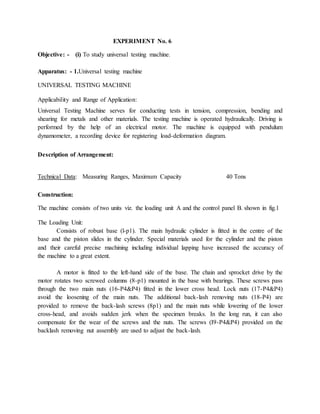
  • 1. EXPERIMENT No. 6 Objective: - (i) To study universal testing machine. Apparatus: - 1.Universal testing machine UNIVERSAL TESTING MACHINE Applicability and Range of Application: Universal Testing Machine serves for conducting tests in tension, compression, bending and shearing for metals and other materials. The testing machine is operated hydraulically. Driving is performed by the help of an electrical motor. The machine is equipped with pendulum dynamometer, a recording device for registering load-deformation diagram. Description of Arrangement: Technical Data: Measuring Ranges, Maximum Capacity 40 Tons Construction: The machine consists of two units viz. the loading unit A and the control panel B. shown in fig.1 The Loading Unit: Consists of robust base (l-p1). The main hydraulic cylinder is fitted in the centre of the base and the piston slides in the cylinder. Special materials used for the cylinder and the piston and their careful precise machining including individual lapping have increased the accuracy of the machine to a great extent. A motor is fitted to the left-hand side of the base. The chain and sprocket drive by the motor rotates two screwed columns (8-p1) mounted in the base with bearings. These screws pass through the two main nuts (16-P4&P4) fitted in the lower cross head. Lock nuts (17-P4&P4) avoid the loosening of the main nuts. The additional back-lash removing nuts (18-P4) are provided to remove the back-lash screws (8p1) and the main nuts while lowering of the lower cross-head, and avoids sudden jerk when the specimen breaks. In the long run, it can also compensate for the wear of the screws and the nuts. The screws (I9-P4&P4) provided on the backlash removing nut assembly are used to adjust the back-lash.
  • 2. Fig.1 (P 1) The lower table (6-P1) is connected to the main piston through a ball and ball seat joint. This joint ensures axial loading. This lower table (6-P1) is rigidly connected to the upper cross-head (20-P1) by two straight columns (9-P1). The lower table and upper cross-head assembly moves up and down with the main piston. The up and down movement of this assembly is guided by eight bearings which slide over the screw columns. Four bearings are fitted in one bearing holder (24-P4) and two such holders are fixed on the upper cross head with the two screwed columns (8-Pl) at their respective centre. The jaws inserts for tensile test specimen along-with the rack jaws slide in the lower and upper cross- heads. The sliding motion of the rack jaws is achieved by rotating the helical toothed pinion by the operating hand wheel (22-P4&P4) provided. Jaw locking handle (2-Pl &P4) is provided to lock the jaws of the lower cross-head after the specimen is clamped. This arrangement ensures
  • 3. firm clamping of the specimen and easy take out of the broken specimen. Separate jaw pieces are provided for different ranges of specimen diameters. Users should confirm that the correct jaw pieces are inserted in the rack jaws before testing the specimen. For changing the jaw pieces first take out the rack jaws. For taking out the rack jaws, remove the top plate (21-P1&P4) from the top of the upper cross-head. Now rotate the pinion and take out the rack jaws by hand from the top. For taking out the jaws from lower cross-head, lock the handle and take out the lower plate (12-P1) from the bottom. The jaws will come out from bottom if you release the handle slowly by un-locking. Take care that the jaws do not fall down on the lower table. After taking out. the rack jaws, removed the clamping strips from the rack jaws, which are screwed to it. Now insert the correct jaw pieces and fix the clamping strips in their position. The jaw pieces must be inserted in the direction of the arrow marked on it. Insert the lower rack jaws from the bottom of the lower cross-head. Care should be taken that both the jaws are inserted at .a time and their top faces come in the same plane when those are taken up to touch each other. Rotate the handle, take up the jaws in the chuck and confirm the piston of the rack jaws. Lock the operation handle in its uppermost piston. Then fix up the lower plate (12-P 1), similarly insert the upper jaws ham the top of the upper cross head and fix up the top plate (21-P 1). Note: The jaws should always be released slowly. The upper and lower jaws are non-interchangeable. Two compression plates viz, upper (11-P1) and lower (7-P1) are provided for conducting compression test. The lower compression plate (7-P1) is to be kept on the lower table (6-P1) in the location hole provided and the upper compression plate (11-P1) is to be clamped to the bottom of the lower cross head. For clamping this plate, take the jaws in the lower cross head to their bottom most position (no head of removal) - keep the top plate (3-P1) on the top lower cross-head, place in such a position that its projected portion fits correctly in the chuck bolt, resulting in the correct position of the control hole. Now insert the clamp stud from the top through the hole of the top plate. The clamp stud will come out from the centre hole of the lower plate (12-P1). Now screw the upper compression plate (II-PI) to the clamp stud and tighten it against the lower plate (12-P1) by the nut (15P1&P4) from above. The space between the lower table and the lower cross head is used from compression, bend and shear tests, and the space between the lower and upper cross heads is used for tension test. In any test, the up and down motion of the lower table and upper cross-head assemble performs the loading action. The mechanical up and down motion of the lower cross-head (10-P1) is provided for rapid initial space adjustment depending on the length or height of the tension and compression test specimen respectively.
  • 4. Bending table (25-P4), Bending Rollers (28-P4) and bending pan (29-P2) are provided as an attachment for carrying out bend test. An elongation scale (30-P4) is kept sliding on the scale rod (31-P4) which is fixed between the lower table and the upper cross-head. Elongation indicating pointer (32-P4) is fixed to the lower cross-head. The scale can slide on the rod when the screw at its back is loosened and can be set to indicate zero before starting the loading on the specimen. Limit switch x 4 provided below the lower table for limiting the maximum stroke of the piston. The Control Panel: The main units in the control panel are:- The oil tank (33-P2) which contains the hydraulic oil level sight class (34-P2) for checking the oil level is fitted to the oil tank. The fitted to the oil tank cover (35-P2) filtrs the incoming oil, to the tank. Drain cock (36-P2) is provided to take out the oil while cleaning the tank. The pump is a positive displacement type pump. This assures continuous high non-pulsating oil current for the smooth application of the load on the specimen. The pump is fitted to the tank cover (35-P2) from bottom which makes it easily assessable. The electric motor is fitted on the plate hinged at the bottom (38-P2). Belt tightening or loosening can be achieved very easily as shown in the fig and the motor can be locked at the desired position by the check nuts. Two valves on the control panel, one at the right side and the other at the left side are used to control the oil flow in the hydraulic systems. The right side valve (39-P2&P2) is a pressure compensated flow control valve. The overload relief valve is adjusted and is locked. The left side valve (4-P2) is a return valve. This valve allows the oil from the cylinder to go back to the tank, there-by reducing the pressure in the cylinder and then the working piston comes down. The rate of oil returns and so the speed of piston return can be adjusted by this valve. If the return valve is closed, oil delivered by the pump passes through the flow control valve (39- P2) (if in open position) to the cylinder and the piston goes up. If it comes across any resistance (i.e. resistance of any test piece), pressure starts developing until either the specimen break of the load reaches the maximum value of the range adjusted. Pressure compensation of the flow control is an unique design which keeps a constant rate of straining regardless of the total load on the specimen and you need not adjust the control knob again and again if it is once adjusted for a particular rate of straining. High pressure oil connection is given from the valve (39-P2) to the cylinder at its centre. This high pressure oil supplied at the cylinder centre serves as a" hydraulic bearing for the piston and reduces the friction, thereby increasing the accuracy. It also helps in getting the pressure compensation effect.
  • 5. Fig. 2 (P2) The confine control valve (41-P2) is specially provided and set by the manufacturer so as to control the rate of loading very precisely by means of the right control valve only. So the adjustment of the needle valve is not to be disturbed by the users. . The needle valve (45-P2) is a damper speed control valve. It controls the return peed of the pendulum when the specimen breaks and the pendulum tries to come down suddenly due to sudden pressure drop in the main cylinder. It obstructs to the return flow of the oil and thus avoids sudden jerks to the dynamometer piston and the indicating mechanism. Dynamometer is a unit which measures and indicates the load on the specimen. The overall accuracy of the machine depends mainly on the accuracy of this unit. It is a pendulum dynamometer consisting of a cylinder in which the piston reciprocates. The cylinder top is
  • 6. connected to the main hydraulic cylinder. So the oil pressure under the work pi ton is transmitted to the small measuring piston in the dynamometer. The displacement of the measuring piston causes the pendulum to deflect as far as the equilibrium point. This deflection represents the measurement of the load on the specimen. The deflection is registered by a pointer on a dial. The pendulum weight is subdivided into several detachable weight discs. Thus various measuring ranges, from full load up to 1/10 of the full load can be obtained. The dynamometer piston is kept rotating at a slow speed. The drive is taken from the same motor (38-P2) driving the pump with worm wheel reduction (14-P2) in between the rotating piston assures dynamic friction conditions and increases the measuring accuracy. The dynamometer is also equipped with an integral check valve. When the specimen breaks, this valve avoids the return oil flow from the measuring cylinder and the oil has to bypass through the damper control valve (45-P2) getting the damping effect. In addition to the accurate load indication on the scale a recording instrument automatically registers the load elongation diagram. A pen (43-P1) fixed to pen holder (44-P1) which is fixed to the main rack, moves across the recording drum (42-P1) as the load increases. At the same time the drum is rotated through small gears by taking movement of the lower table. The movement of the lower table is taken through chain and sprockets without slip and friction as the specimen under test is elongated. Thus an automatic graph of load against elongation is plotted. A big size load indicating dial (46-Pl), fitted with a glass cover (47-Pl) is mounted at the front side of the control panel. The range indicating dial, located at the back side of the load indicating dial is to be adjusted for the particular range selected. A range adjuster knob (48-P1) is provided for this adjustment. A zero adjusting knob (l3-Pl) provided at the right hand side serves for initial zero adjustment.