
Recommended
Recommended
More Related Content
What's hot
What's hot (20)
Similar to Hyundai hdf70 3 forklift truck service repair manual
Similar to Hyundai hdf70 3 forklift truck service repair manual (20)
More from idkkddkmd
More from idkkddkmd (20)
Recently uploaded
Recently uploaded (20)
Hyundai hdf70 3 forklift truck service repair manual
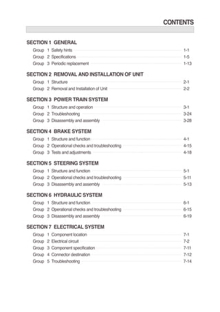
- 1. CONTENTS SECTION 1 GENERAL Group 1 Safety hints 1-1 Group 2 Specifications 1-5 Group 3 Periodic replacement 1-13 SECTION 2 REMOVAL AND INSTALLATION OF UNIT Group 1 Structure 2-1 Group 2 Removal and Installation of Unit 2-2 SECTION 3 POWER TRAIN SYSTEM Group 1 Structure and operation 3-1 Group 2 Troubleshooting 3-24 Group 3 Disassembly and assembly 3-28 SECTION 4 BRAKE SYSTEM Group 1 Structure and function 4-1 Group 2 Operational checks and troubleshooting 4-15 Group 3 Tests and adjustments 4-18 SECTION 5 STEERING SYSTEM Group 1 Structure and function 5-1 Group 2 Operational checks and troubleshooting 5-11 Group 3 Disassembly and assembly 5-13 SECTION 6 HYDRAULIC SYSTEM Group 1 Structure and function 6-1 Group 2 Operational checks and troubleshooting 6-15 Group 3 Disassembly and assembly 6-19 SECTION 7 ELECTRICAL SYSTEM Group 1 Component location 7-1 Group 2 Electrical circuit 7-2 Group 3 Component specification 7-11 Group 4 Connector destination 7-12 Group 5 Troubleshooting 7-14
- 2. SECTION 8 MAST Group 1 Structure 8-1 Group 2 Operational checks and troubleshooting 8-5 Group 3 Adjustment 8-8 Group 4 Removal and installation 8-9
- 3. SECTION 6 HYDRAULICSYSTEM Group 1 Structure and function 6-1 Group 2 Operational checks and troubleshooting 6-15 Group 3 Disassembly and assembly 6-19
- 4. 6-1 GROUP 1 STRUCTURE ANDFUNCTION SECTION 6 HYDRAULICSYSTEM 1. HYDRAULIC CIRCUIT D503HS01 1 Hydraulic gear pump 2 Flow regulator 3 Priority valve 4 Main control valve 5 Steering unit 6 Brake valve 7 Steering cylinder 8 Tilt cylinder 9 Lift cylinder 10 Suction filter 11 Return filter 12 Down control valve 13 Down safety valve 14 Hydraulic tank
- 5. 6-2 D503HS02 WHEN THE LIFT CONTROL LEVER IS IN THE LIFT POSITION 1) When the lift control lever is pulled back, the spool on the first block is moves to lift position. The oil from hydraulic gear pump(1) flows into main control valve(4) and then goes to the large chamber of lift cylinder(9) by pushing the load check valve of the spool. The oil from the small chamber of lift cylinder(9) returns to hydraulic oil tank(14) at the same time. When this happens, the forks go up.
- 6. 6-3 D503HS03 WHEN THE LIFT CONTROL LEVER IS IN THE LOWER POSITION 2) When the lift control is pushed forward, the spool on the first block is moved to lower position. The work port(B1) and the small chamber and the large chamber are connected to the return passage, so the lift will be lowered due to its own weight.
- 7. 6-4 D503HS04 WHEN THE TILT CONTROL LEVER IS IN THE FORWARD POSITION 3) When the tilt control lever is pushed forward, the spool on the second block is moved to tilt forward position. The oil from hydraulic gear pump(1) flows into main control valve(4) and then goes to the large chamber of tilt cylinder(8) by pushing the load check valve of the spool. The oil at the small chamber of tilt cylinder(8) returns to hydraulic tank(14) at the same time. When this happens, the mast tilt forward.
- 8. 6-5 D503HS05 WHEN THE TILT CONTROL LEVER IS IN THE BACKWARD POSITION 4) When the tilt control lever is pulled back, the spool on the second block is moved to tilt backward position. The oil from hydraulic gear pump(1) flows into main control valve(4) and then goes to the small chamber of tilt cylinder(8) by pushing the load check valve of spool. The oil at the large chamber of tilt cylinder(8) returns to hydraulic tank(14) at the same time. When this happens, the mast tilt backward.
- 9. 6-6 2. HYDRAULIC GEAR PUMP STRUCTURE D503HS06 1 Retaining ring 2 Seal retainer 3 Seal gland 4 Inner shaft seal 5 Outer shaft seal 6 O-ring seal 7 Drive gear 8 Driven gear 9 Wear plate 10 Center section 11 Lock washer 12 Nut 13 Stud bolt 14 Front cover kit 15 Rear cover kit 16 Coupling kit 1)
- 10. 6-7 3. MAIN CONTROL VALVE STRUCTURE (3 Spool) D353HS07 1 Special nut 2 O-ring 3 Plug 4 O-ring 5 O-ring 6 Plug 7 Spool cap 8 Seal plate 9 Spring seat 10 Spool end 11 Spring 12 O-ring 13 Cap screw 14 Plug 15 Screw 16 Wiper 17 O-ring 18 Spring seat 19 Spring 20 Spool end 21 Spring 22 Spool 23 Main relief valve 24 Spool 25 Piston 26 Spool 27 O-ring 28 Inlet housing 29 Spool housing 30 Spool housing 31 Spool housing 32 Outlet housing 33 Puppet 34 Tie rod 35 Tie rod 36 Special nut 37 Inlet section assy 38 Outlet section assy 39 Spool section assy 40 Spool section assy 41 Spool section assy 1) Port name Inlet port Outlet port Gauge port Work port Size 1-5/16-12UN 1-5/16-12UN PF1/4 1-1/16-12UN
- 11. 6-8 LIFT SECTION OPERATION Lift position B1 Load check valve(1) SECTION A-A A A 2) (1) When the lift control lever is pulled back, the spool moves to the right and the neutral passage is closed. The oil supplied from the pump pushes up the load check valve(1) and flow into lift cylinder port(B1). The pump pressure reaches proportionally the load of cylinder and fine control finished by shut off of the neutral passage. The return oil from cylinder flows into the tank. D353HS08
- 12. 6-9 Lower position (2) D353HS09 When the lift control lever is pushed forward, the spool moves to the left and the neutral passage is closed. The spool moves to the lift lower position, opening up the neutral passage to tank and (B1)
- 13. 6-10 TILT SECTION OPERATION Tilt forward position 3) (1) D353HS10 When the tilt control lever is pushed forward, the spool moves to the left and the neutral passage is closed. The oil supplied from the pump pushes up the load check valve(1) and flow into tilt cylinder port(A2). The pump pressure reaches proportionally the load of cylinders and fine control finished by closing the neutral passage. The return oil from cylinder port(B2) flows into the tank through the hole of the tilt lock spool.
- 14. 6-11 Tilt backward position (2) D353HS11 When the tilt control lever is pulled back, the spool moves to the right and the neutral passage is closed. The oil supplied from the pump pushes up the load check valve(1) and flows into tilt cylinder port(B2). The pump pressure reaches proportionally the load of cylinder and fine control finished by shut off of the neutral passage. The return oil from cylinder port(A2) flows into the tank via the low pressure passage.
- 15. 6-12 The oil pressure in the high pressure port HP has reached the setting of the pilot puppet spring force and unseats the pilot puppet E and oil flows around the puppet through the cross drilled holes and to the low pressureareaLP. MAINRELIEFVALVE Pressuresetting A good pressure gauge must be installed in the line which is in communication with the work port relief. A load must be applied in a manner to reach the set pressure of the relief unit. Procedure Loosen lock nut. Set adjusting nut to desired pressure setting. If desired pressure setting cannot be achieved,addor removeshims as required. Tightenlock nut. Retestin similar manner as above. 4) (1)
- 16. Thank you very much for your reading. Please Click Here. Then Get COMPLETE MANUAL. NO WAITING NOTE: If there is no response to click on the link above, please download the PDF document first and then click on it.
- 17. 6-13 The imbalance of pressure on the inside as compared to that of the high pressure port HP, forces the relief valve puppet D to open and relieve the oil directly to the low pressure chamber LP inthevalve. D353HS20 D353HS21 The loss of oil behind puppet C, effected by the opening of pilot puppet E, causes puppet C to move back and seat against pilot puppet E. This shuts off the oil flow to the area behind relief valve puppet D, and causes a lowpressure area internally. Asanti void The anti-void unit supplies oil to the high pressure port HP when cavitation has occurred. A lower pressure exists in the port HP compared to the low pressure chamber LP. The difference between the effective area of diameter A and G causes imbalance of the check valve puppet K which unseats, thus allowingoilfromthelow pressure chamber LP to enter the port HP andfill thevoid. HP K A G 7406S6-28(1)
- 18. 6-14 4. LIFT CYLINDER D503HS12 1 Tube assy 2 Rod 3 Gland 4 DU bushing 5 Rod seal 6 Dust wiper 7 O-ring 8 O-ring 9 Piston 10 Piston seal 11 Back up ring 12 Wear ring 13 Retaining ring 14 Spacer 15 O-ring 16 Spacer 5. TILT CYLINDER D503HS13 1 Tube assy 2 Rod 3 Gland 4 DU bushing 5 Rod seal 6 Back up ring 7 Dust wiper 8 Snap ring 9 O-ring 10 Back up ring 11 O-ring 12 Piston 13 O-ring 14 Glyd ring 15 Wear ring 16 Nylon nut 17 Rod eye 18 Hexagon bolt 19 Hexagon nut 20 Spring washer 21 DU bushing 22 DU bushing 23 Tilt cylinder spacer 24 O-ring