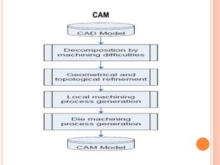
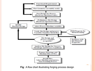
TECHNICAL SEMINAR ON
USE OF COMPUTER IN FORGING
INDUSRTY
PRESENTED BY
SUSHEEL YADAV
M.TECH. 2nd YEAR (FFT)
INTRODUCTION:
Global competition requires that forging industry utilize
practical and proven
 computer aided design (CAD),
 computer aided manufacturing (CAM) and
 computer aided engineering (CAE)
technologies for rapid and cost effective process
design and die manufacture.
Recently,
 finite element (FE) simulation software has become
an integral part of forging process design to analyze and
optimize the metal flow and conduct die stress analysis
before conducting forging trials.
CAD
 Today, design of forged part and forging die is done
in the engineering and design department.
 Die analysis is performed on the CAD model of die
cavities with metal flow simulation .
 Die designers define forged part and dies according
to CAD models.
 Some commonly used CAD software are
 CATIA
 SOLIDWORKS
 AUTOCAD
 PRO-E
CAM
 The production method that requires a computer to
control the machines is called a computer aided
manufacturing, simply called CAM.
 CAM is closely related to the computer-aided
design (CAD) because the output information about
the products from the CAD can assist the
composing of production program.
 These machines are normally known as CNC
machines.
The design of CNC machine
 Firstly, CNC machine needs a precise path
measuring system, so that the computer can
detect the position of tools and work pieces
automatically.
 Supporting machinery components
 For example, a tools clamp, an automatic tools
changing system, a tools holding device and a
transfer system, etc, are needed to make the
changing of tools easier.
 Coordinate system
 Some CNC machines are
 CNC drilling machine
 CNC lathe
 CNC milling machine
CAM
Finite Element Analysis (FEA)
 The Finite Element Analysis (FEA) is a numerical
method for solving problems of engineering.
 Useful for problems with complicated geometries,
loadings, and material properties where analytical
solutions can not be obtained.
Fig : A flow chart illustrating forging process design
STEPS IN DEFORM-3D
 Pre processor
 Simulator
 Post processor
INPUT VARIABLES IN THE FEM MODELS
 accuracy of the input data, namely,
a) flow stress as a function of temperature, strain,
strain rate and microstructure,
b) friction characteristics at the interface.
 Work piece and tool material properties
 Interface friction
PRE PROCESSOR
 Create a new problem
 Loading object data
 Importing Dies
 Top Die
 Bottom Die
 Setting Die Movement
 Setting Object Temperature
 Setting Material Properties
 Setting Simulation Controls
 Object Positioning
SIMULATOR
 Post-Processing the Results
 After the simulation has completed, click on under.
The DEFORM-3D Post-processor will appear.
Application of CAE in Precision Forging
The most effective and mature applications of simulation in
forging are
a) development of forging sequences
b) die stress analysis
c) solving problems related to an existing manufacturing
sequence, etc.
APPLICATION OF CAE IN PRECISION FORGING -
CASE STUDIES
 Advanced orbital forging simulation
 Micro forming
 Clinching Simulation
 Hydraulic crimping
 Hot Forging Simulation of Aerospace Components
Use of computer in forging indusrty.ppt

Use of computer in forging indusrty.ppt

  • 1.
    TECHNICAL SEMINAR ON USEOF COMPUTER IN FORGING INDUSRTY PRESENTED BY SUSHEEL YADAV M.TECH. 2nd YEAR (FFT)
  • 2.
    INTRODUCTION: Global competition requiresthat forging industry utilize practical and proven  computer aided design (CAD),  computer aided manufacturing (CAM) and  computer aided engineering (CAE) technologies for rapid and cost effective process design and die manufacture. Recently,  finite element (FE) simulation software has become an integral part of forging process design to analyze and optimize the metal flow and conduct die stress analysis before conducting forging trials.
  • 3.
    CAD  Today, designof forged part and forging die is done in the engineering and design department.  Die analysis is performed on the CAD model of die cavities with metal flow simulation .  Die designers define forged part and dies according to CAD models.  Some commonly used CAD software are  CATIA  SOLIDWORKS  AUTOCAD  PRO-E
  • 4.
    CAM  The productionmethod that requires a computer to control the machines is called a computer aided manufacturing, simply called CAM.  CAM is closely related to the computer-aided design (CAD) because the output information about the products from the CAD can assist the composing of production program.  These machines are normally known as CNC machines.
  • 5.
    The design ofCNC machine  Firstly, CNC machine needs a precise path measuring system, so that the computer can detect the position of tools and work pieces automatically.  Supporting machinery components  For example, a tools clamp, an automatic tools changing system, a tools holding device and a transfer system, etc, are needed to make the changing of tools easier.  Coordinate system  Some CNC machines are  CNC drilling machine  CNC lathe  CNC milling machine
  • 6.
  • 7.
    Finite Element Analysis(FEA)  The Finite Element Analysis (FEA) is a numerical method for solving problems of engineering.  Useful for problems with complicated geometries, loadings, and material properties where analytical solutions can not be obtained.
  • 8.
    Fig : Aflow chart illustrating forging process design
  • 9.
    STEPS IN DEFORM-3D Pre processor  Simulator  Post processor
  • 10.
    INPUT VARIABLES INTHE FEM MODELS  accuracy of the input data, namely, a) flow stress as a function of temperature, strain, strain rate and microstructure, b) friction characteristics at the interface.  Work piece and tool material properties  Interface friction
  • 11.
    PRE PROCESSOR  Createa new problem  Loading object data  Importing Dies  Top Die  Bottom Die  Setting Die Movement  Setting Object Temperature  Setting Material Properties  Setting Simulation Controls  Object Positioning
  • 13.
  • 14.
     Post-Processing theResults  After the simulation has completed, click on under. The DEFORM-3D Post-processor will appear.
  • 16.
    Application of CAEin Precision Forging The most effective and mature applications of simulation in forging are a) development of forging sequences b) die stress analysis c) solving problems related to an existing manufacturing sequence, etc.
  • 17.
    APPLICATION OF CAEIN PRECISION FORGING - CASE STUDIES  Advanced orbital forging simulation  Micro forming  Clinching Simulation  Hydraulic crimping  Hot Forging Simulation of Aerospace Components