ENGINEERI
NG DESIGN
Engineering design is a systematic,
iterative, and creative process
aimed at developing solutions to
challenges. It involves the creation,
testing, and refinement of models
or prototypes to address specific
problems effectively.
In Engineering design there are
various methodologies to develop
solutions:
‱ 3d modeling
‱ drafting
‱ Engg. simulation
ENGINEERI
NG DESIGN
3D MODELING, DRAFTING, ENGG. SIMULATION
SOFTWARE
Computer-Aided Styling Computer-Aided Design Computer-Aided Engineering Computer-Aided Manufacturin
CAS CAD CAE CAM
It is where you sit with a designer and
make a quick, simple, model from
his/her sketches. You use very low
degree curves and surfaces. This enable
the designer to request changes, as you
go, which are easy and quick to do,
because the model has direct active
memory.
Computer-Aided Styling
CAS
CAD stands for Computer-Aided Design. It's a process that uses
computers to create, modify, analyze, or optimize designs. CAD
can be used to create 2D drawings or 3D models of products
before they are manufactured.
CAD software can be classified into the following types:
‱ 2D CAD
‱ 3D CAD
CAD software is used by architects, engineers, drafters, and artists.
It can help designers:
‱ Increase productivity
‱ Improve the quality of their designs
‱ Improve communication through documentation
‱ Create a database for manufacturing
‱ Protect products and inventions when used in patent
applications
Computer-Aided Design
CAD
Computer-aided engineering (CAE) is the use of
computer software to simulate performance in order to
improve product designs or assist in the resolution of
engineering problems for a wide range of industries.
This includes simulation, validation and optimization of
products, processes, and manufacturing tools.
In the preprocessing phase, engineers model the
geometry (or a system representation) and the physical
properties of the design, as well as the environment in
the form of applied loads or constraints. Next, the
model is solved using an appropriate mathematical
formulation of the underlying physics.
Computer-Aided Engineering
Stress and dynamics
analysis
optimization
computational fluid dynamics
CAE
CAM stands for computer-aided
manufacturing. CAM software is used to
convert computer-aided design (CAD) models
into information that can be used by
machines. CAM software is used to develop
programs for a variety of CNC machines,
such as milling and turning machines, or
machines for cutting edge machining or
additive manufacturing
Computer-Aided Manufacturing
CAM
‱ Machining accuracy: Human error is all but eliminated with CAM, and
computer-generated toolpaths are inherently more precise.
‱ Faster job completion: Not only does CAM software save hours of hand-
programming time, it also helps to reduce cycle times by offering
optimized toolpaths.
‱ Material and tool savings: The best CAM systems reduce accidental
gouges, continuously analyze stock material for warping or other
issues, and use tools as efficiently as possible to extend their life.
‱ Digital review: In-software simulation checks for possible programming
errors as well as presents a visual model of the machining process.
ADVANTAGES
CAM
CNC
Milling Machine
CNC Lathe Machine
CNC Laser
Cutting
Machine
CNC Waterjet
Cutting Machine
CNC Plasma
Cutting Machine
CNC Router
Machine
CNC Wire Cut EDM
3D Printer
THANK
YOU

engineering design and manufacturing .pptx

  • 1.
  • 2.
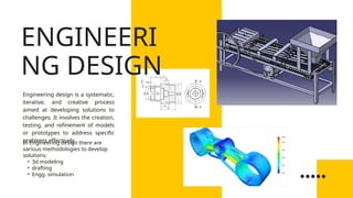
    Engineering design isa systematic, iterative, and creative process aimed at developing solutions to challenges. It involves the creation, testing, and refinement of models or prototypes to address specific problems effectively. In Engineering design there are various methodologies to develop solutions: ‱ 3d modeling ‱ drafting ‱ Engg. simulation ENGINEERI NG DESIGN
  • 3.
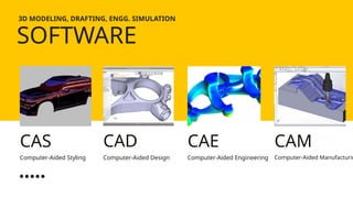
    3D MODELING, DRAFTING,ENGG. SIMULATION SOFTWARE Computer-Aided Styling Computer-Aided Design Computer-Aided Engineering Computer-Aided Manufacturin CAS CAD CAE CAM
  • 4.
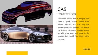
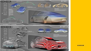
    It is whereyou sit with a designer and make a quick, simple, model from his/her sketches. You use very low degree curves and surfaces. This enable the designer to request changes, as you go, which are easy and quick to do, because the model has direct active memory. Computer-Aided Styling CAS
  • 8.
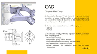
    CAD stands forComputer-Aided Design. It's a process that uses computers to create, modify, analyze, or optimize designs. CAD can be used to create 2D drawings or 3D models of products before they are manufactured. CAD software can be classified into the following types: ‱ 2D CAD ‱ 3D CAD CAD software is used by architects, engineers, drafters, and artists. It can help designers: ‱ Increase productivity ‱ Improve the quality of their designs ‱ Improve communication through documentation ‱ Create a database for manufacturing ‱ Protect products and inventions when used in patent applications Computer-Aided Design CAD
  • 12.
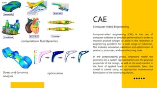
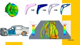
    Computer-aided engineering (CAE)is the use of computer software to simulate performance in order to improve product designs or assist in the resolution of engineering problems for a wide range of industries. This includes simulation, validation and optimization of products, processes, and manufacturing tools. In the preprocessing phase, engineers model the geometry (or a system representation) and the physical properties of the design, as well as the environment in the form of applied loads or constraints. Next, the model is solved using an appropriate mathematical formulation of the underlying physics. Computer-Aided Engineering Stress and dynamics analysis optimization computational fluid dynamics CAE
  • 15.
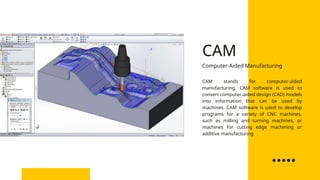
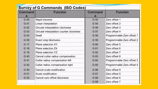
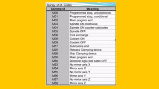
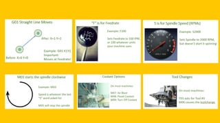
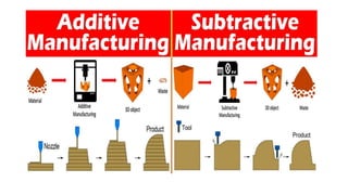
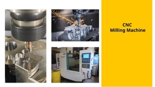
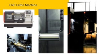
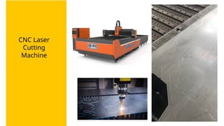
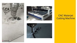
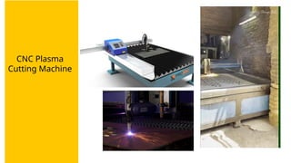
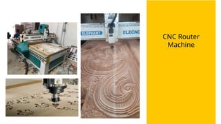
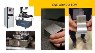
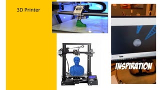
    CAM stands forcomputer-aided manufacturing. CAM software is used to convert computer-aided design (CAD) models into information that can be used by machines. CAM software is used to develop programs for a variety of CNC machines, such as milling and turning machines, or machines for cutting edge machining or additive manufacturing Computer-Aided Manufacturing CAM
  • 17.
    ‱ Machining accuracy:Human error is all but eliminated with CAM, and computer-generated toolpaths are inherently more precise. ‱ Faster job completion: Not only does CAM software save hours of hand- programming time, it also helps to reduce cycle times by offering optimized toolpaths. ‱ Material and tool savings: The best CAM systems reduce accidental gouges, continuously analyze stock material for warping or other issues, and use tools as efficiently as possible to extend their life. ‱ Digital review: In-software simulation checks for possible programming errors as well as presents a visual model of the machining process. ADVANTAGES CAM
  • 22.
  • 23.
  • 24.
  • 25.
  • 26.
  • 27.
  • 28.
  • 29.
  • 30.