Introduction to mechanical engineering design & manufacturing with
The document provides an introduction to mechanical engineering design and manufacturing using Fusion 360. It discusses key aspects of mechanical engineering design including the design process, digital manufacturing, CAD/CAM/CAE software such as Fusion 360, and CNC machining. Some key points covered include the steps in the engineering design process, advantages of digital manufacturing, differences between CAD, CAM, and CAE tools, and differences between numeric control and computer numeric control systems.
Mechanical Engineering Design
Engineering design is the process of devising a system, component, or process to meet
desired needs.
It is a decision making process, in which the engineering sciences and mathematics are
applied to convert resources optimally to meet a stated objective.
Among the fundamental elements of the design process are the establishments of objectives
and criteria, synthesis, analysis, construction, testing and evaluation.
Mechanical designs means the design of components and systems of a mechanical nature-
machines, products, structures, devices and instruments.
For the most part mechanical design uses mathematics, materials and the engineering
mechanics sciences.
Additionally, it uses engineering graphics and the ability to communicate verbally to clearly
express your ideas.
Mechanical engineering design includes all mechanical design, but it is a broader study
because it includes all the disciplines of mechanical engineering, such as thermal, fluids, and
heat transfer sciences too.
3.
Steps of designprocess
1. Recognize the need
2. Problem definition
3. Gathering of information
4. Concept generation
5. Concept selection
6. Communication
7. Detailed design and analysis
8. Prototype and testing
9. Manufacturing
10.Life cycle maintenance
4.
What is digitalmanufacturing?
Digital manufacturing is the application of computer systems to
manufacturing services, supply chains, products and processes.
Digital manufacturing technologies link systems and processes across all
areas of production to create an integrated approach to manufacturing,
from design to production and on to the servicing of the final product.
Digital manufacturing is an integrated approach to manufacturing that is
centered around a computer system.
5.
Aspects of digitalmanufacturing
It can be broken down into three main areas :-
Product Life Cycle
Smart factory
Value Chain management
The product life cycle begins with engineering design before moving on to
encompass sourcing, production and service life. Each step uses digital data to allow
for revisions to designs specifications during the manufacturing process.
The smart factory involves the use of smart machines, sensors and tooling to provide
real time feedback about the processes and manufacturing technology. By uniting
operations technology and information technology, this digital transformation allows
for greater visibility of factory processes, control and optimisation to improve
performances.
The value chain management focuses on reducing resources to create an optimal
process with decreased inventories while maintaining product quality and customer
satisfaction.
6.
Advantages of digitalmanufacturing
Increased efficiency is accomplished by a joined-up manufacturing process which
eliminates errors due to lost or misinterpreted data which is common for paper
based processes.
With a quicker turnaround across all levels of the value chain, digital
manufacturing offers reduced costs, while allowing for design changes to be
implemented in real time and also lowering maintenance costs.
The real time manufacturing visibility afforded by digital technologies provides
improved insights for critical decisions and a faster pace of innovation.
It allows an entire manufacturing process to be created virtually so that designers
can test the process before investing time and money into the physical
implementation.
Cloud based manufacturing can be used for this modelling, taking open access
information from a number of sources to develop reconfigurable production lines
and thereby improve efficiency.
7.
What is thefuture of digital manufacturing?
Digital manufacturing looks set to continue and grow in the future as the
use of information for production processes becomes increasingly
automated.
With systems that are able to interact with each other, the growth of
industry 4.0 looks to set to continue the trend for joined-up production in
order to increase competition and improve and streamline processes.
8.
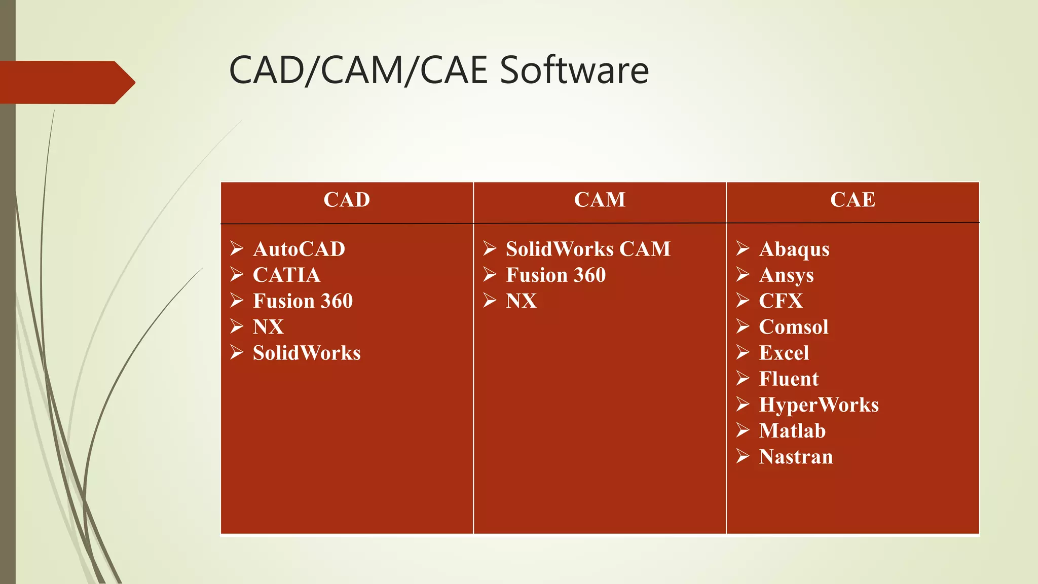
CAD/CAM/CAE
Computer AidedDesign (CAD), it is the use of computer systems to assist in the
creation, modification, analysis, and optimisation of a design. CAD is three
dimensional tool for developing 2D and 3D models which can later be translated
into a product.
Typical tools of the CAD are-
Tolerance Analysis
Mass Property Calculations
Finite element modelling and visualization
Computer Aided Manufacturing (CAM), it is specifically designed for computer
systems to plan, manage, and control manufacturing operations. It is used on the
direct and indirect computer interfaces with the plant’s production resources. It
also takes care of numerical control of machine tools.
Computer Aided Engineering (CAE), it is a use of computer systems to analyse
CAD geometry. It allows a designer to simulate and study how the product will
behave, allowing for optimization.
What is fusion360?
Fusion 360 is a cloud based CAD/CAM tool for collaborative product
development that combines industrial design, mechanical engineering and
machine tool programming into one software solution.
Fusion 360 is an excellent tool for the precise modelling of 2D and 3D objects,
but you can do much more with it, such as animate your design, render objects,
simulate loads and even prepare models for CNC machining.
Fusion 360 combines fastenings the organic modelling with precise solid
modelling, allowing you to make your design manufacturable.
In fusion 360, we can make a complex shape transition to solid model and export
it to an STL or NetFabb to 3D print in a matter of minutes.
11.
Difference b/w Tinkercadand Fusion 360
Both Tinkercad and Fusion 360 keep your data in the cloud and allow you to
collaborate with other users. Fusion 360 though, provides extra power for
management of who you invite to collaborate on your designs and it has more
control for versioning designs. Versioning means, Fusion 360 saves a new version
of the file every time you save.
We can create basic shapes like Tinkercad but so much more. Fusion 360 is a
sketch based CAD program that also lets you create what are called primitives,
which is used in both with a little bit of twist. The difference is that we don’t have
to group them together to add or remove geometry. Fusion 360 uses what are
called features. A feature is a tool that allows us to add, subtract or modify
geometry in some way. Fusion 360 also gives us what’s called free form
modelling or Fforms for short.
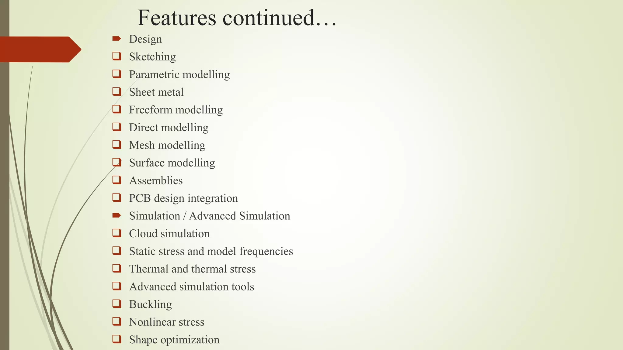
Features continued…
Design
Sketching
Parametric modelling
Sheet metal
Freeform modelling
Direct modelling
Mesh modelling
Surface modelling
Assemblies
PCB design integration
Simulation / Advanced Simulation
Cloud simulation
Static stress and model frequencies
Thermal and thermal stress
Advanced simulation tools
Buckling
Nonlinear stress
Shape optimization
14.
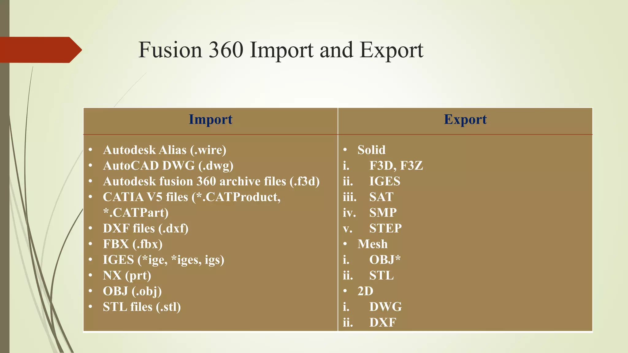
Fusion 360 Importand Export
Import
• Autodesk Alias (.wire)
• AutoCAD DWG (.dwg)
• Autodesk fusion 360 archive files (.f3d)
• CATIA V5 files (*.CATProduct,
*.CATPart)
• DXF files (.dxf)
• FBX (.fbx)
• IGES (*ige, *iges, igs)
• NX (prt)
• OBJ (.obj)
• STL files (.stl)
Export
• Solid
i. F3D, F3Z
ii. IGES
iii. SAT
iv. SMP
v. STEP
• Mesh
i. OBJ*
ii. STL
• 2D
i. DWG
ii. DXF
15.
NC and CNC
Numeric Control (NC) systems use fixed logical functions to handle a machine
tool or the machining process. NC specifies the control of the machine movements
and various different functions with the help of instructions represented as a
sequence of numbers.
In order to feed the instructions into the NC machines, the external
medium is used, such as paper tape or magnetic tape. It reads the information from
this tape processing it steps by step, which is stored in the memory of the control
system known as buffer storage. Therefore, when the machine is operating on a
single instruction block, it reads the next block from the tapes and saves it in the
memory of the machine control system.
Computer Numeric Control (CNC), it is generated by merging the computer with
the Numerical control. It uses internal microprocessors(computers) which are
comprised of memory registers. The memory registers stores various routines that
can successfully manipulate logical functions.
16.
Features of CNC
The part program can act as the input to the controller unit with the help of a
keyboard or a paper tape so that it can be read by the tape reader within a control
unit.
The inserted part program can be repeatedly used.
We can also revise and optimise part program at the machine tool itself.
It uses special sub-programs made for repetitive machining sequence in order to
reduce the input information.
CNC machines can also show the results in different form without actually
executing the part program over the machine tool.
CNC machines also permit the coverage for any changes in the modifications in
the dimensions of the cutting tool.
It also provides information on machine utilization that is useful to the
management.
17.
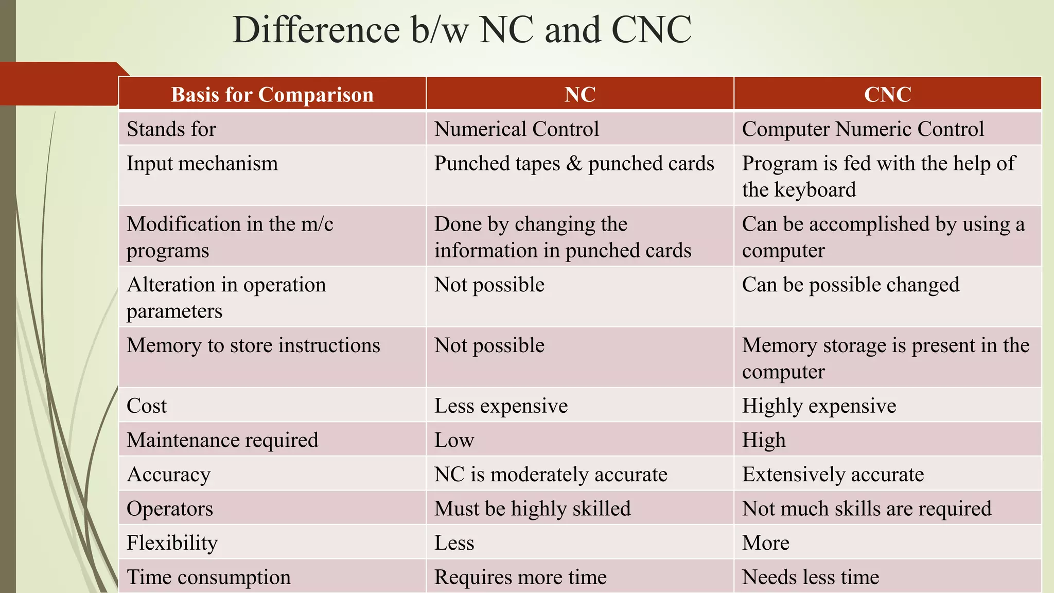
Difference b/w NCand CNC
Basis for Comparison NC CNC
Stands for Numerical Control Computer Numeric Control
Input mechanism Punched tapes & punched cards Program is fed with the help of
the keyboard
Modification in the m/c
programs
Done by changing the
information in punched cards
Can be accomplished by using a
computer
Alteration in operation
parameters
Not possible Can be possible changed
Memory to store instructions Not possible Memory storage is present in the
computer
Cost Less expensive Highly expensive
Maintenance required Low High
Accuracy NC is moderately accurate Extensively accurate
Operators Must be highly skilled Not much skills are required
Flexibility Less More
Time consumption Requires more time Needs less time