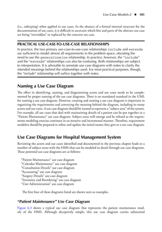
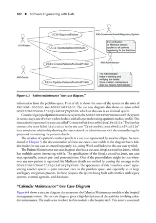
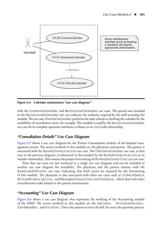
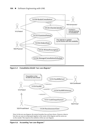
97
Chapter 6
Use Case Models-2:
Use Case Diagrams and
Requirements Modeling
Learning Objectives
◾
◾ Model requirements in the problem space with use cases
◾
◾ Create use case diagrams with actors, use cases, and relationships
◾
◾ Study the three relationships in a use case diagram: include, extends, inherits
◾
◾ Understand the importance of system boundaries in use case diagrams
◾
◾ Add notes in use case diagrams to improve their readability
◾
◾ Understand the strengths and weaknesses of use case diagrams
Use Case Diagrams
This chapter discusses use case diagrams. Extending the discussion in the previous chapter, this
chapter demonstrates how to place actors and use cases in a visual format.
Use case diagrams provide a comprehensive visual overview of the requirements of a system in
the problem space. Fowler (2003)1 calls them a “graphical table of contents” of the use cases. Use
case diagrams contain actors, use cases, their relationships, and notes. Use case diagrams are ideal
for engaging users and ensuring their participation in modeling requirements.
As mentioned in the previous chapter, use case diagrams show, through actors, where the users
fit in the overall solution and how they will use the system. Use case modeling workshops usu-
ally have increased participation from users in the software development process and result in an
overall increase in their satisfaction from solutions. Good software engineers are therefore keen to
understand and draw use case diagrams to ensure their efforts are directed toward fulfilling user
needs.
98  ◾  Software Engineering with UML
Notations of a Use Case Diagram
Figure 6.1 shows the notations in a use case diagram. They are actor, use case, relations, boundary,
and notes. These are discussed in greater detail next.
Boundary
The system boundary is an important notation in a use case diagram. The system boundary,
shown by a rectangular box in Figure 6.1, separates actors from use cases. The actors are all outside
of the boundary and the use cases are all inside. Although the boundary line is optional in the
UML standard, it is advisable to draw it whenever possible. If the modeling tool does not support
the drawing of a boundary, creating a visual arrangement by keeping the use cases all together in
the middle of the diagram surrounded by actors is a good option for the aesthetic quality of a use
case diagram.
Notes
Notes add semantic and aesthetic value to a use case diagram (as it does to all other diagrams in
the UML). Notes are shown with a corner-cut rectangle (also known as a dog-eared rectangle) in
Figure 6.1. Notes in use case diagrams can be used to explain the use case relationships (discus-
sion follows), provide additional information on actors, and highlight the importance of certain
use cases.
Actor
Actors, as discussed in previous chapters, represent the roles played by system users. Actors can
also represent an interface to another system or an external device. Actors are represented by stick
Actor
Use case
Actor to use case
association
System
boundary
Notes
Extension of a
use case by another
Inclusion of a
use case by another
Inheritance
<<extends>>
<<include>>
Figure 6.1  Major notations in a use case diagram.
Use Case Models-2  ◾  99
figures, as shown in Figure 6.1. Since an actor is outside the system boundary, it is only interfaced
with, not built. Actors and their documentation were discussed in the previous chapter.
Use Case
The use case, discussed in the previous chapter, is shown visually by an ellipse, as shown in Figure
6.1. A use case represents a cohesive set of interactions between the actor and the system. Pictorially
a use case simply represents the interaction but does not show it in the diagram. The documenta-
tion of a use case contains the details of the interaction. Use cases and their documentation were
discussed in the previous chapter.
Relationships
Relationships in a use case diagram are a powerful mechanism to organize and reuse requirements.
There are three main types of relationships in use case diagrams:
	 1.	Actor to actor—This is the generalization relationship and represented by the inheritance
arrow in Figure 6.1. This relationship was also discussed in the previous chapter (notably
Figure 5.3).
	 2.	Actor to use case—The relationship between an actor and a use case is called an association,
also occasionally called “communication” because it represents a communication between
the actor and the system. This association is represented by a straight line in Figure 6.1. The
association is an interface through which an actor interacts with the system. Occasionally,
an association line may have an arrowhead (not shown in Figure 6.1), representing the actor
initiating the use case. This direction on the association relationship is only shown if abso-
lutely necessary.
	 3.	Use case to use case—There are three specific relationships permitted between two use cases
in a use case diagram. They are the include, extends, and inherits relationships, as shown
by the three arrows and appropriate stereotypes on them in Figure 6.1. These relationships
deserve a detailed discussion, which follows
Use Case Relationships
Figure 6.2 shows a sample use case diagram. This diagram is meant to highlight the three rela-
tionships between use cases. Note that in Figure 6.2, the actor to UsecaseA relationship is simply
shown as a line (association), as discussed earlier. That relationship is an actor-to-use-case relation-
ship and needs to be noted as separate from the discussion on use-case-to-use-case relationships.
Include
When a part of the behavior documented within a use case is likely to be reused by other parts
of a system, it is advisable to factor out that common behavior and show it as an independent use
case. This newly created use case can then be “included” in the original use case from which it was
factored out. The newly created use case also becomes available to other use cases in the system.
The relationship between two such use cases is that of includes, and the arrowhead on this relation-
ship points from the including use case to the use case being included. In Figure 6.2, UsecaseA is
100  ◾  Software Engineering with UML
shown including UsecaseB. Hence the arrow points from UsecaseA to UsecaseB with the stereo-
type <<include>> written on the relationship.
Extends
When a use case extends or specializes the behavior of another use case, the relationship is
“extends.” This extension may be undertaken in order to add functionality to an existing use
case. The extension can also superimpose a new special type of behavior on an existing behavior.
The extends relationship may also describe an anomalous situation or an exception, beyond that
provided in the base use case (Henderson-Sellers and Unhelkar, 2000).2 The extending use case
may thus be thought of as representing an “option.” In the “extends” relationship between two
use cases, the arrowhead points to the use case that is being extended. UsecaseC in Figure 6.2
shows how it extends UsecaseA. The arrow is pointing from UsecaseC to UsecaseA, and the word
<<extends>> is stereotyped on the relationship.
Inherits (Generalize)
“Inherits,” also known as generalization, literally means a use case implements the behavior
described by another higher-level abstract use case. While an abstract use case contains a general-
ized description of how an actor will use the system, the corresponding concrete use case, which
is inherited from the generalized use case, will describe the actual steps in the identification of the
user. Unless a use case has been correctly documented as an abstract use case, the generalization
relationship will tend to confuse rather than prove valuable (Henderson-Sellers and Unhelkar,
2000).2 This is because inheritance is meant to represent one behavior (that described by the
abstract use case) being replaced by another (that described by the concrete use case). Cockburn
(2000) also notes that there isn’t actually an agreed semantics for generalization/specialization
UsecaseA
UsecaseA <<include>> UsecaseB
UsecaseC <<extends>> UsecaseA
UsecaseD <<inherit>> UsecaseA
Labeling include and extends is mandatory
Practical Tips:
Use cases are IDEAL for requirements modeling
rather than system design; they DON’T crash
systems; include and extends are indicative
relationships only – don’t be pedantic about
them but add notes for explanations
UsecaseD
UsecaseC
UsecaseB
Actor
<<extends>>
<<include>>
Figure 6.2  UML notations for use case relationships.
Use Case Models-2  ◾  101
(i.e., subtyping) when applied to use cases. In the absence of a formal internal structure for the
documentation of use cases, it is difficult to ascertain which bits and parts of the abstract use case
are being “overridden” or replaced by the concrete use case.
PRACTICAL USE-CASE-TO-USE-CASE RELATIONSHIPS
In practice, the two primary use-case-to-use-case relationships include and extends
are sufficient to model almost all requirements in the problem space, obviating the
need to use the generalization relationship. In practice, however, the “include”
and the “extends” relationships can also be confusing. Both relationships are subject
to interpretation. It is advisable to annotate use case diagrams with notes to clarify the
intended meanings behind the relationships used. For most practical purposes, though,
the “include” relationship will suffice together with notes.
Naming a Use Case Diagram
The effort in identifying, naming, and diagramming actors and use cases needs to be comple-
mented by proper naming of the use case diagrams. There is no mandated standard in the UML
for naming a use case diagram. However, creating and naming a use case diagram is important in
organizing the requirements and conveying the meaning behind the diagram, including its many
actors and use cases. A use case diagram should be named to represent a “subject area” of the system.
For example, all use cases that deal with maintaining details of a patient can be put together in a
“Patient Maintenance” use case diagram. Subject areas will emerge and be refined as the require-
ments modeling exercise continues in an iterative and incremental manner. Therefore, requirement
modelers should be prepared to refine and update the initial names they give to a use case diagram.
Use Case Diagrams for Hospital Management System
Revisiting the actors and use cases identified and documented in the previous chapter leads to a
number of subject areas with the HMS that can be modeled in detail through use case diagrams.
These potential use case diagrams are as follows:
“Patient Maintenance” use case diagram
“Calendar Maintenance” use case diagram
“Consultation Details” use case diagram
“Accounting” use case diagram
“Surgery Details” use case diagram
“Inventory and Reordering” use case diagram
“User Administration” use case diagram
The first four of these diagrams listed are shown next as examples.
“Patient Maintenance” Use Case Diagram
Figure 6.3 shows a typical use case diagram that represents the patient maintenance mod-
ule of the HMS. Although deceptively simple, this use case diagram carries substantial
102  ◾  Software Engineering with UML
information from the problem space. First of all, it shows the users of the system in the roles of
Patient, Doctor, and Administrator. The use case diagram also shows an actor called
GovernmentHealthRegulatorySystem, which in this case is an external system.
Consideringatypicalpatientmaintenancesystem,theAdministratorinteractswiththesystem
invariousways,oneofwhichiswhenhedealswithallaspectsofcreatingapatient’smedicalprofile.This
interactionisrepresentedbyausecasecalled“CreatesPatientsMedicalProfile.”Thelinethat
connects the actor Administrator to the use case “CreatesPatientsMedicalProfile”
is an association relationship showing the interaction of the administrator with the system during the
process of maintaining the patient’s details.
The creation of a patient’s medical profile is a use case represented by another ellipse. As men-
tioned in Chapter 5, the documentation of these use cases is not visible in the diagram but is hid-
den inside the use case or created separately, i.e., using Word and linked to this use case symbol.
The Patient Maintenance use case diagram also has a use case, RegistersPatient, which
has multiple actors interacting with it. The specification of the RegistersPatient use case
may, optionally, contain pre- and postconditions. One of the preconditions might be that when-
ever any new patient is registered, his Medicare details are verified by passing the message to the
GovernmentHealthRegulatorySystem. The appearance of this “interface actor” repre-
senting another system is quite common even in the problem space, and especially so in large
and legacy integration projects. In these projects, the system being built will interface with legacy
systems, external agencies, and databases.
“Calendar Maintenance” Use Case Diagram
Figure 6.4 shows a use case diagram that represents the Calendar Maintenance module of the hospital
management system. The use case diagram gives a high-level picture of the activities involving calen-
dar maintenance. The main actor involved in this module is the hospital staff. This actor is associated
UC10-RegistersPatient A90-GovernmentHealthRegulatorySystem
A80-Administrator
For verification
of Medicare details -
applies to all patients
registering for the first time.
The Administrator
helps in creating and
verifying the details.
Once created, maintenance
does not require Administrator
A10-Patient
A60-Doctor
UC12-MaintainsPatientDetails
UC14-CreatesPatientsMedicalProfile
UC16-UpdatesPatientsMedicalProfile
:
Figure 6.3  Patient maintenance “use case diagram.”
Use Case Models-2  ◾  103
with the CreatesCalendar and MaintainsCalendar use cases. The special note attached
to the MaintainsCalendar use case indicates the authority required by the staff accessing this
module. The use case ChecksCalendar performs the tasks related to checking the calendar for the
availability of consultation times, for example. This module is used by the MaintainsCalendar
use case for its complete operation and hence is shown as an include relationship.
“Consultation Details” Use Case Diagram
Figure 6.5 shows a use case diagram for the Patient Consultation module of the hospital man-
agement system. The actors involved in this module are the physician and patient. The patient is
associated with the BooksConsultation use case. The ChecksCalendar use case, as first
seen in the previous diagram, is referenced in this module by the BooksConsultation as an
include relationship. This ensures the proper functioning of the BooksConsultation use case.
Note that use cases are not restricted to a single use case diagram and can be included in
another use case diagram for reusability. The physician and the patient interact with the
ExaminesPatient use case, indicating that both actors are required for the functioning
of this module. The physician is also associated with other use cases such as OrdersTests,
WritesPrescription, and ManagesConsultationSchedule, which deal with other
miscellaneous tasks related to the patient examination.
“Accounting” Use Case Diagram
Figure 6.6 shows a use case diagram that represents the working of the Accounting module
of the HMS. The actors involved in this module are the Patient, PrivatePatient,
CardReader, and Printer. Once the patient receives the bill, he starts the payment process.
UC20-CreatesCalendar
UC22-MaintainsCalendar
‘A50-Staff’
UC24-ChecksCalendar
Some maintenance
activities (such as booking
a vacation) will require
appropriate authorization.
include
:
Figure 6.4  Calendar maintenance “use case diagram.”
104  ◾  Software Engineering with UML
'UC30-BooksConsultation'
'UC24-ChecksCalendar'
'UC32-ExaminesPatient'
'UC34-OrdersTests'
'UC35-WritesPrescription'
'UC36-ManagesConsultationSchedule'
This calendar is updated
by the Doctors with their availability
Involved in
manual bookings
of consultations
'A80-Administrator'
'A10-Patient'
'A64-Physician'
include
:
Figure 6.5  Consultation details “use case diagram.”
Precondition is that
the Bill has been Issued
'UC55-PaysBillByCard'
'A00-CardReader'
'A00-Printer'
'UC56-PaysBillOnInternet'
'UC50-PaysBill'
'UC57-CashChequePayment'
'UC58-PlacesInsuranceClaim'
'A20-PrivatePatient'
Note: In this use case diagram, the system boundary has not been drawn. However, observe
how the use cases are all grouped together in the center of the diagram and the actors are
on the outside. This improves the aesthetics of the use case diagram.
'A10-Patient' extends
extends
extends
Figure 6.6  Accounting “use case diagram.”
Use Case Models-2  ◾  105
This is indicated as the precondition of the PaysBill use case. The PrivatePatient,
apart from performing all the tasks associated with the normal Patient, also interacts with the
PlacesInsuranceClaims use case. This is represented as the generalization between the
Patient and the PrivatePatient actor (note the arrow shape).
The use cases PaysBillByCard and PaysBillOnInternet form the two methods of
paying the bill and, hence, extend the PaysBill use case. In the case of PaysBillByCard,
the use of the external system CardReader is shown as an actor interacting with the use case.
Where the bill is paid by cash or cheque, the CashChequePayment use case becomes active and
the receipt is printed via the external system Printer, also shown as an actor.
Strengths and Weaknesses of Use Case Diagrams
Strengths of Use Case Diagrams
What follows are some of the strengths of use case diagrams in practice. Awareness of these
strengths at the start of a requirements modeling exercise is most helpful in improving the quality
of the model of the problem space (MOPS):
◾
◾ Use case diagrams model the communication between actors and a system and provide a
summary view of system usage and behavior. This summary view provides an immediate
understanding of the overall requirements—and then readers can drill down to specific
actors and use cases of interest.
◾
◾ Use case diagrams can organize requirements by showing the intended behavior of a system.
They are helpful in identifying the core requirements of the system, as well as their vari-
ants. A walkthrough of these requirements in a use case diagram can help shed light on and
improve those requirements early in the life cycle of a software development project.
◾
◾ Use case diagrams can effectively summarize the interactions needed between users (actors)
and a system that will provide value to business.
◾
◾ Use case diagrams show graphically the opportunities for reuse of use cases; this reuse is at
the requirements level and is modeled within a use case diagram through include and extends
mechanisms.
◾
◾ Use case diagrams can aid in dividing a large system into multiple modules. Each module
can itself be represented by a use case diagram. (Note, however, that there are no levels
within a use case diagram.)
◾
◾ The boundary feature of use case diagrams helps in isolating the internal and the external
elements of a system—with the actors all being outside and the use cases inside the system.
◾
◾ Evaluating and prioritizing requirements: use case diagrams can be used to evaluate the
requirements. With the help of use case diagrams, it is possible to ascertain a set of business
processes that represent some significant and central functionality that can be categorized
as a high-priority job. The remaining business processes (or functionalities) may take less
precedence over the significant ones.
◾
◾ Facilitating project estimation: use case diagrams can be used to estimate project size and
complexity as they show the context in which a use case exists and relates to other use cases
and actors. For example, use cases involving an easy user interface and requiring minimal
database interaction could be classified as an easy task. On the other hand, a complex use
case involving an intricate user interface and multiple database interactions can be classified
as a complex task and assign the highest value in the time scale.
106  ◾  Software Engineering with UML
Weaknesses of Use Case Diagrams
Following are some of the weaknesses of use case diagrams in practice. Awareness of these weak-
nesses at the start of a requirements modeling exercise is also very helpful in improving the quality
of the MOPS:
◾
◾ Similar to use cases, the use case diagrams are not object-oriented and do not provide
any active application of the concept of object orientation to the development of the
solution.
◾
◾ Imprecise relationships: The relationships between two use cases shown in a use case dia-
gram (i.e., <<include>>, <<extends>>, and <<inherits>>) do not have rigorous defini-
tions within the UML. These relationships provide a generic description of how use cases
relate to each other. Practical software projects do not use these relationships as rigorously
defined but, rather, as indicative of the connections between two use cases. Notes are needed
to provide value to the relationships.
◾
◾ Granularity in use case diagrams is a matter of aesthetics. A use case diagram can easily lose
its aesthetic quality by either having too many or too few use cases. Furthermore, a system
can have different levels of granularity and, hence, create complexity in terms of creating,
reading, and understanding the use case diagram.
◾
◾ Use case diagrams do not show any flow or dependencies in the system. They only provide
a high-level picture of the system and have no features to represent the sequence of actions
and alternative actions.
Common Errors in Use Case Diagrams and How to Rectify Them
Common Errors Rectifying the Errors Examples
Assuming that there is only
one use case diagram for
the system
The system’s requirements view
should be expressed with multiple
use case diagrams. Each use case
diagram represents a key subject
area of the system.
See Figures 6.3
through 6.5.
One use case can appear
in only one use case
diagram
Use cases can appear in multiple
use case diagrams depending on
the needs of the system. Multiple
appearances of use cases in use
case diagrams show their use in
different contexts.
UC24-ChecksCalendar
use case appears in
“Calendar Maintenance”
and “Consultation
Details” use case
diagrams
One actor can appear in
only one use case diagram
An actor can be shown in different
use case diagrams to represent
different ways in which the actor
achieves goals by using the system
“A10_Patient” appears in
multiple use case
diagrams in this chapter.
Use Case Models-2  ◾  107
Discussion Questions
	 1.	How is a use case diagram different from a use case?
	 2.	Is it possible to draw a use case diagram without writing a use case? Answer with reasons.
	 3.	Provide an example for each of the three relationships on a use case diagram: actor–actor,
actor–use case, and use case–use case with examples.
	 4.	Why is a use case diagram called a visual table of contents for requirements? Agree or dis-
agree with this statement by providing arguments.
Common Errors Rectifying the Errors Examples
An actor-use case
combination is limited to
only one package.
A package is only an organizational
entity. Actors and use cases can
come from different packages and
appear in many packages.
Use namespace
(discussed in a previous
chapter) to identify the
source of an actor or
use case package.
One can code directly
from use cases.
Use cases are no longer object-
oriented in nature; they are
excellent for capturing
requirements, but their models
are fuzzy and not as precise as,
say, class diagrams.
Not recommended.
They are treated as data
flow diagrams (DFD)
They look like a DFD but they do
not show a flow of data like a DFD
does.
There is no “if-then-else”
or any layering in use
case diagrams.
Every communication
between actors and use
cases needs to be
represented in the use
case diagram.
If this is attempted, the use case
diagrams can look like a spider’s
web. Actors should be abstracted
and the diagrams annotated in
order to create an aesthetically
good diagram.
See Figure 6.6, where the
private patient is
derived from the
patient—and in that way,
the clutter in the
diagram is reduced.
Use case diagrams are
treated as deliverables
More than 50% of the work in use
case modeling deals with
documenting use cases and not
drawing use case diagrams.
This is why use case
diagrams are called
“visual tables of
contents” of
requirements.
Showing an inheritance
relationship between an
actor and use case
Only communication line
representing an association
relationship is possible between
actor and use cases.
Revisit the relationships
shown in Figure 6.2.
Showing an <<inherits>>
or <<includes>>
between an actor and a
use case
These are only use-case-to-use-case
relationships.
Revisit the relationships
shown in Figure 6.2.
108  ◾  Software Engineering with UML
	 5.	What is the importance of the system boundary in a use case diagram?
	 6.	What is the element in a use case diagram that is “interfaced” with and what is the element
that is “built”?
	 7.	Why should there be a separate actor hierarchy drawn in the modeling tool at all? Discuss
its advantages.
	 8.	What is the relevance of writing <<include>>, <<extends>>, and <<inherits>> for the
use case relationship? Give an example for each one.
	 9.	List and provide examples of the three use-case-to-use-case relationships.
	 10.	What is the importance of notes in a use case diagram?
	 11.	What are the two key strengths of a use case diagram?
	 12.	What are the two key weaknesses of a use case diagram?
Team Project Case Study
	 1.	Place the actors and use cases identified in the previous chapter in a use case diagram using
your modeling tool.
	 2.	These use case diagrams will be within each package in the modeling tool.
	 3.	Name the use case diagrams appropriately to represent the subject area for that diagram.
	 4.	Since actors and use cases can appear in various diagrams, it is expected that there will be
more than one use case diagram per package. Therefore, there can be a total of 8 to 10 use
case diagrams for the project.
	 5.	Be sure to use both <<include>> and <<extend>> relationships in the use case diagrams.
	 6.	Be sure to have at least one nonhuman actor in at least one use case diagram.
	 7.	Ensure you have shown the system boundary in at least one use case diagram.
	 8.	Stereotype the actors and use cases appearing in the use case diagram.
	 9.	It is normal to find additional actors and use cases at this stage. Document any additional
actors and use cases using appropriate templates.
	 10.	Create a separate diagram showing the actor hierarchies within the modeling tool (this will
be a diagram similar to Figure 5.2 in the previous chapter).
	 11.	Provide relevant stereotypes for the use cases (initially they will all be <<entity>>.
(Stereotypes are discussed in detail in Chapter 10; therefore, you will have to come back to
these diagrams to update them with stereotypes.)
	 12.	Add detailed notes on ALL use case diagrams, providing additional explanations about the
diagram. Make sure that there are no inconsistencies among the members of the group.
Endnotes
	 1.	Fowler, Martin (2003), UML Distilled, 3rd Edition, Addison-Wesley, USA.
	 2.	Henderson-Sellers, B., and Unhelkar, B. (2000), OPEN Modelling with the UML, Addison-Wesley,
UK.

use case diagram

  • 1.
    97 Chapter 6 Use CaseModels-2: Use Case Diagrams and Requirements Modeling Learning Objectives ◾ ◾ Model requirements in the problem space with use cases ◾ ◾ Create use case diagrams with actors, use cases, and relationships ◾ ◾ Study the three relationships in a use case diagram: include, extends, inherits ◾ ◾ Understand the importance of system boundaries in use case diagrams ◾ ◾ Add notes in use case diagrams to improve their readability ◾ ◾ Understand the strengths and weaknesses of use case diagrams Use Case Diagrams This chapter discusses use case diagrams. Extending the discussion in the previous chapter, this chapter demonstrates how to place actors and use cases in a visual format. Use case diagrams provide a comprehensive visual overview of the requirements of a system in the problem space. Fowler (2003)1 calls them a “graphical table of contents” of the use cases. Use case diagrams contain actors, use cases, their relationships, and notes. Use case diagrams are ideal for engaging users and ensuring their participation in modeling requirements. As mentioned in the previous chapter, use case diagrams show, through actors, where the users fit in the overall solution and how they will use the system. Use case modeling workshops usu- ally have increased participation from users in the software development process and result in an overall increase in their satisfaction from solutions. Good software engineers are therefore keen to understand and draw use case diagrams to ensure their efforts are directed toward fulfilling user needs.
  • 2.
    98  ◾  SoftwareEngineering with UML Notations of a Use Case Diagram Figure 6.1 shows the notations in a use case diagram. They are actor, use case, relations, boundary, and notes. These are discussed in greater detail next. Boundary The system boundary is an important notation in a use case diagram. The system boundary, shown by a rectangular box in Figure 6.1, separates actors from use cases. The actors are all outside of the boundary and the use cases are all inside. Although the boundary line is optional in the UML standard, it is advisable to draw it whenever possible. If the modeling tool does not support the drawing of a boundary, creating a visual arrangement by keeping the use cases all together in the middle of the diagram surrounded by actors is a good option for the aesthetic quality of a use case diagram. Notes Notes add semantic and aesthetic value to a use case diagram (as it does to all other diagrams in the UML). Notes are shown with a corner-cut rectangle (also known as a dog-eared rectangle) in Figure 6.1. Notes in use case diagrams can be used to explain the use case relationships (discus- sion follows), provide additional information on actors, and highlight the importance of certain use cases. Actor Actors, as discussed in previous chapters, represent the roles played by system users. Actors can also represent an interface to another system or an external device. Actors are represented by stick Actor Use case Actor to use case association System boundary Notes Extension of a use case by another Inclusion of a use case by another Inheritance <<extends>> <<include>> Figure 6.1  Major notations in a use case diagram.
  • 3.
    Use Case Models-2 ◾  99 figures, as shown in Figure 6.1. Since an actor is outside the system boundary, it is only interfaced with, not built. Actors and their documentation were discussed in the previous chapter. Use Case The use case, discussed in the previous chapter, is shown visually by an ellipse, as shown in Figure 6.1. A use case represents a cohesive set of interactions between the actor and the system. Pictorially a use case simply represents the interaction but does not show it in the diagram. The documenta- tion of a use case contains the details of the interaction. Use cases and their documentation were discussed in the previous chapter. Relationships Relationships in a use case diagram are a powerful mechanism to organize and reuse requirements. There are three main types of relationships in use case diagrams: 1. Actor to actor—This is the generalization relationship and represented by the inheritance arrow in Figure 6.1. This relationship was also discussed in the previous chapter (notably Figure 5.3). 2. Actor to use case—The relationship between an actor and a use case is called an association, also occasionally called “communication” because it represents a communication between the actor and the system. This association is represented by a straight line in Figure 6.1. The association is an interface through which an actor interacts with the system. Occasionally, an association line may have an arrowhead (not shown in Figure 6.1), representing the actor initiating the use case. This direction on the association relationship is only shown if abso- lutely necessary. 3. Use case to use case—There are three specific relationships permitted between two use cases in a use case diagram. They are the include, extends, and inherits relationships, as shown by the three arrows and appropriate stereotypes on them in Figure 6.1. These relationships deserve a detailed discussion, which follows Use Case Relationships Figure 6.2 shows a sample use case diagram. This diagram is meant to highlight the three rela- tionships between use cases. Note that in Figure 6.2, the actor to UsecaseA relationship is simply shown as a line (association), as discussed earlier. That relationship is an actor-to-use-case relation- ship and needs to be noted as separate from the discussion on use-case-to-use-case relationships. Include When a part of the behavior documented within a use case is likely to be reused by other parts of a system, it is advisable to factor out that common behavior and show it as an independent use case. This newly created use case can then be “included” in the original use case from which it was factored out. The newly created use case also becomes available to other use cases in the system. The relationship between two such use cases is that of includes, and the arrowhead on this relation- ship points from the including use case to the use case being included. In Figure 6.2, UsecaseA is
  • 4.
    100  ◾  SoftwareEngineering with UML shown including UsecaseB. Hence the arrow points from UsecaseA to UsecaseB with the stereo- type <<include>> written on the relationship. Extends When a use case extends or specializes the behavior of another use case, the relationship is “extends.” This extension may be undertaken in order to add functionality to an existing use case. The extension can also superimpose a new special type of behavior on an existing behavior. The extends relationship may also describe an anomalous situation or an exception, beyond that provided in the base use case (Henderson-Sellers and Unhelkar, 2000).2 The extending use case may thus be thought of as representing an “option.” In the “extends” relationship between two use cases, the arrowhead points to the use case that is being extended. UsecaseC in Figure 6.2 shows how it extends UsecaseA. The arrow is pointing from UsecaseC to UsecaseA, and the word <<extends>> is stereotyped on the relationship. Inherits (Generalize) “Inherits,” also known as generalization, literally means a use case implements the behavior described by another higher-level abstract use case. While an abstract use case contains a general- ized description of how an actor will use the system, the corresponding concrete use case, which is inherited from the generalized use case, will describe the actual steps in the identification of the user. Unless a use case has been correctly documented as an abstract use case, the generalization relationship will tend to confuse rather than prove valuable (Henderson-Sellers and Unhelkar, 2000).2 This is because inheritance is meant to represent one behavior (that described by the abstract use case) being replaced by another (that described by the concrete use case). Cockburn (2000) also notes that there isn’t actually an agreed semantics for generalization/specialization UsecaseA UsecaseA <<include>> UsecaseB UsecaseC <<extends>> UsecaseA UsecaseD <<inherit>> UsecaseA Labeling include and extends is mandatory Practical Tips: Use cases are IDEAL for requirements modeling rather than system design; they DON’T crash systems; include and extends are indicative relationships only – don’t be pedantic about them but add notes for explanations UsecaseD UsecaseC UsecaseB Actor <<extends>> <<include>> Figure 6.2  UML notations for use case relationships.
  • 5.
    Use Case Models-2 ◾  101 (i.e., subtyping) when applied to use cases. In the absence of a formal internal structure for the documentation of use cases, it is difficult to ascertain which bits and parts of the abstract use case are being “overridden” or replaced by the concrete use case. PRACTICAL USE-CASE-TO-USE-CASE RELATIONSHIPS In practice, the two primary use-case-to-use-case relationships include and extends are sufficient to model almost all requirements in the problem space, obviating the need to use the generalization relationship. In practice, however, the “include” and the “extends” relationships can also be confusing. Both relationships are subject to interpretation. It is advisable to annotate use case diagrams with notes to clarify the intended meanings behind the relationships used. For most practical purposes, though, the “include” relationship will suffice together with notes. Naming a Use Case Diagram The effort in identifying, naming, and diagramming actors and use cases needs to be comple- mented by proper naming of the use case diagrams. There is no mandated standard in the UML for naming a use case diagram. However, creating and naming a use case diagram is important in organizing the requirements and conveying the meaning behind the diagram, including its many actors and use cases. A use case diagram should be named to represent a “subject area” of the system. For example, all use cases that deal with maintaining details of a patient can be put together in a “Patient Maintenance” use case diagram. Subject areas will emerge and be refined as the require- ments modeling exercise continues in an iterative and incremental manner. Therefore, requirement modelers should be prepared to refine and update the initial names they give to a use case diagram. Use Case Diagrams for Hospital Management System Revisiting the actors and use cases identified and documented in the previous chapter leads to a number of subject areas with the HMS that can be modeled in detail through use case diagrams. These potential use case diagrams are as follows: “Patient Maintenance” use case diagram “Calendar Maintenance” use case diagram “Consultation Details” use case diagram “Accounting” use case diagram “Surgery Details” use case diagram “Inventory and Reordering” use case diagram “User Administration” use case diagram The first four of these diagrams listed are shown next as examples. “Patient Maintenance” Use Case Diagram Figure 6.3 shows a typical use case diagram that represents the patient maintenance mod- ule of the HMS. Although deceptively simple, this use case diagram carries substantial
  • 6.
    102  ◾  SoftwareEngineering with UML information from the problem space. First of all, it shows the users of the system in the roles of Patient, Doctor, and Administrator. The use case diagram also shows an actor called GovernmentHealthRegulatorySystem, which in this case is an external system. Consideringatypicalpatientmaintenancesystem,theAdministratorinteractswiththesystem invariousways,oneofwhichiswhenhedealswithallaspectsofcreatingapatient’smedicalprofile.This interactionisrepresentedbyausecasecalled“CreatesPatientsMedicalProfile.”Thelinethat connects the actor Administrator to the use case “CreatesPatientsMedicalProfile” is an association relationship showing the interaction of the administrator with the system during the process of maintaining the patient’s details. The creation of a patient’s medical profile is a use case represented by another ellipse. As men- tioned in Chapter 5, the documentation of these use cases is not visible in the diagram but is hid- den inside the use case or created separately, i.e., using Word and linked to this use case symbol. The Patient Maintenance use case diagram also has a use case, RegistersPatient, which has multiple actors interacting with it. The specification of the RegistersPatient use case may, optionally, contain pre- and postconditions. One of the preconditions might be that when- ever any new patient is registered, his Medicare details are verified by passing the message to the GovernmentHealthRegulatorySystem. The appearance of this “interface actor” repre- senting another system is quite common even in the problem space, and especially so in large and legacy integration projects. In these projects, the system being built will interface with legacy systems, external agencies, and databases. “Calendar Maintenance” Use Case Diagram Figure 6.4 shows a use case diagram that represents the Calendar Maintenance module of the hospital management system. The use case diagram gives a high-level picture of the activities involving calen- dar maintenance. The main actor involved in this module is the hospital staff. This actor is associated UC10-RegistersPatient A90-GovernmentHealthRegulatorySystem A80-Administrator For verification of Medicare details - applies to all patients registering for the first time. The Administrator helps in creating and verifying the details. Once created, maintenance does not require Administrator A10-Patient A60-Doctor UC12-MaintainsPatientDetails UC14-CreatesPatientsMedicalProfile UC16-UpdatesPatientsMedicalProfile : Figure 6.3  Patient maintenance “use case diagram.”
  • 7.
    Use Case Models-2 ◾  103 with the CreatesCalendar and MaintainsCalendar use cases. The special note attached to the MaintainsCalendar use case indicates the authority required by the staff accessing this module. The use case ChecksCalendar performs the tasks related to checking the calendar for the availability of consultation times, for example. This module is used by the MaintainsCalendar use case for its complete operation and hence is shown as an include relationship. “Consultation Details” Use Case Diagram Figure 6.5 shows a use case diagram for the Patient Consultation module of the hospital man- agement system. The actors involved in this module are the physician and patient. The patient is associated with the BooksConsultation use case. The ChecksCalendar use case, as first seen in the previous diagram, is referenced in this module by the BooksConsultation as an include relationship. This ensures the proper functioning of the BooksConsultation use case. Note that use cases are not restricted to a single use case diagram and can be included in another use case diagram for reusability. The physician and the patient interact with the ExaminesPatient use case, indicating that both actors are required for the functioning of this module. The physician is also associated with other use cases such as OrdersTests, WritesPrescription, and ManagesConsultationSchedule, which deal with other miscellaneous tasks related to the patient examination. “Accounting” Use Case Diagram Figure 6.6 shows a use case diagram that represents the working of the Accounting module of the HMS. The actors involved in this module are the Patient, PrivatePatient, CardReader, and Printer. Once the patient receives the bill, he starts the payment process. UC20-CreatesCalendar UC22-MaintainsCalendar ‘A50-Staff’ UC24-ChecksCalendar Some maintenance activities (such as booking a vacation) will require appropriate authorization. include : Figure 6.4  Calendar maintenance “use case diagram.”
  • 8.
    104  ◾  SoftwareEngineering with UML 'UC30-BooksConsultation' 'UC24-ChecksCalendar' 'UC32-ExaminesPatient' 'UC34-OrdersTests' 'UC35-WritesPrescription' 'UC36-ManagesConsultationSchedule' This calendar is updated by the Doctors with their availability Involved in manual bookings of consultations 'A80-Administrator' 'A10-Patient' 'A64-Physician' include : Figure 6.5  Consultation details “use case diagram.” Precondition is that the Bill has been Issued 'UC55-PaysBillByCard' 'A00-CardReader' 'A00-Printer' 'UC56-PaysBillOnInternet' 'UC50-PaysBill' 'UC57-CashChequePayment' 'UC58-PlacesInsuranceClaim' 'A20-PrivatePatient' Note: In this use case diagram, the system boundary has not been drawn. However, observe how the use cases are all grouped together in the center of the diagram and the actors are on the outside. This improves the aesthetics of the use case diagram. 'A10-Patient' extends extends extends Figure 6.6  Accounting “use case diagram.”
  • 9.
    Use Case Models-2 ◾  105 This is indicated as the precondition of the PaysBill use case. The PrivatePatient, apart from performing all the tasks associated with the normal Patient, also interacts with the PlacesInsuranceClaims use case. This is represented as the generalization between the Patient and the PrivatePatient actor (note the arrow shape). The use cases PaysBillByCard and PaysBillOnInternet form the two methods of paying the bill and, hence, extend the PaysBill use case. In the case of PaysBillByCard, the use of the external system CardReader is shown as an actor interacting with the use case. Where the bill is paid by cash or cheque, the CashChequePayment use case becomes active and the receipt is printed via the external system Printer, also shown as an actor. Strengths and Weaknesses of Use Case Diagrams Strengths of Use Case Diagrams What follows are some of the strengths of use case diagrams in practice. Awareness of these strengths at the start of a requirements modeling exercise is most helpful in improving the quality of the model of the problem space (MOPS): ◾ ◾ Use case diagrams model the communication between actors and a system and provide a summary view of system usage and behavior. This summary view provides an immediate understanding of the overall requirements—and then readers can drill down to specific actors and use cases of interest. ◾ ◾ Use case diagrams can organize requirements by showing the intended behavior of a system. They are helpful in identifying the core requirements of the system, as well as their vari- ants. A walkthrough of these requirements in a use case diagram can help shed light on and improve those requirements early in the life cycle of a software development project. ◾ ◾ Use case diagrams can effectively summarize the interactions needed between users (actors) and a system that will provide value to business. ◾ ◾ Use case diagrams show graphically the opportunities for reuse of use cases; this reuse is at the requirements level and is modeled within a use case diagram through include and extends mechanisms. ◾ ◾ Use case diagrams can aid in dividing a large system into multiple modules. Each module can itself be represented by a use case diagram. (Note, however, that there are no levels within a use case diagram.) ◾ ◾ The boundary feature of use case diagrams helps in isolating the internal and the external elements of a system—with the actors all being outside and the use cases inside the system. ◾ ◾ Evaluating and prioritizing requirements: use case diagrams can be used to evaluate the requirements. With the help of use case diagrams, it is possible to ascertain a set of business processes that represent some significant and central functionality that can be categorized as a high-priority job. The remaining business processes (or functionalities) may take less precedence over the significant ones. ◾ ◾ Facilitating project estimation: use case diagrams can be used to estimate project size and complexity as they show the context in which a use case exists and relates to other use cases and actors. For example, use cases involving an easy user interface and requiring minimal database interaction could be classified as an easy task. On the other hand, a complex use case involving an intricate user interface and multiple database interactions can be classified as a complex task and assign the highest value in the time scale.
  • 10.
    106  ◾  SoftwareEngineering with UML Weaknesses of Use Case Diagrams Following are some of the weaknesses of use case diagrams in practice. Awareness of these weak- nesses at the start of a requirements modeling exercise is also very helpful in improving the quality of the MOPS: ◾ ◾ Similar to use cases, the use case diagrams are not object-oriented and do not provide any active application of the concept of object orientation to the development of the solution. ◾ ◾ Imprecise relationships: The relationships between two use cases shown in a use case dia- gram (i.e., <<include>>, <<extends>>, and <<inherits>>) do not have rigorous defini- tions within the UML. These relationships provide a generic description of how use cases relate to each other. Practical software projects do not use these relationships as rigorously defined but, rather, as indicative of the connections between two use cases. Notes are needed to provide value to the relationships. ◾ ◾ Granularity in use case diagrams is a matter of aesthetics. A use case diagram can easily lose its aesthetic quality by either having too many or too few use cases. Furthermore, a system can have different levels of granularity and, hence, create complexity in terms of creating, reading, and understanding the use case diagram. ◾ ◾ Use case diagrams do not show any flow or dependencies in the system. They only provide a high-level picture of the system and have no features to represent the sequence of actions and alternative actions. Common Errors in Use Case Diagrams and How to Rectify Them Common Errors Rectifying the Errors Examples Assuming that there is only one use case diagram for the system The system’s requirements view should be expressed with multiple use case diagrams. Each use case diagram represents a key subject area of the system. See Figures 6.3 through 6.5. One use case can appear in only one use case diagram Use cases can appear in multiple use case diagrams depending on the needs of the system. Multiple appearances of use cases in use case diagrams show their use in different contexts. UC24-ChecksCalendar use case appears in “Calendar Maintenance” and “Consultation Details” use case diagrams One actor can appear in only one use case diagram An actor can be shown in different use case diagrams to represent different ways in which the actor achieves goals by using the system “A10_Patient” appears in multiple use case diagrams in this chapter.
  • 11.
    Use Case Models-2 ◾  107 Discussion Questions 1. How is a use case diagram different from a use case? 2. Is it possible to draw a use case diagram without writing a use case? Answer with reasons. 3. Provide an example for each of the three relationships on a use case diagram: actor–actor, actor–use case, and use case–use case with examples. 4. Why is a use case diagram called a visual table of contents for requirements? Agree or dis- agree with this statement by providing arguments. Common Errors Rectifying the Errors Examples An actor-use case combination is limited to only one package. A package is only an organizational entity. Actors and use cases can come from different packages and appear in many packages. Use namespace (discussed in a previous chapter) to identify the source of an actor or use case package. One can code directly from use cases. Use cases are no longer object- oriented in nature; they are excellent for capturing requirements, but their models are fuzzy and not as precise as, say, class diagrams. Not recommended. They are treated as data flow diagrams (DFD) They look like a DFD but they do not show a flow of data like a DFD does. There is no “if-then-else” or any layering in use case diagrams. Every communication between actors and use cases needs to be represented in the use case diagram. If this is attempted, the use case diagrams can look like a spider’s web. Actors should be abstracted and the diagrams annotated in order to create an aesthetically good diagram. See Figure 6.6, where the private patient is derived from the patient—and in that way, the clutter in the diagram is reduced. Use case diagrams are treated as deliverables More than 50% of the work in use case modeling deals with documenting use cases and not drawing use case diagrams. This is why use case diagrams are called “visual tables of contents” of requirements. Showing an inheritance relationship between an actor and use case Only communication line representing an association relationship is possible between actor and use cases. Revisit the relationships shown in Figure 6.2. Showing an <<inherits>> or <<includes>> between an actor and a use case These are only use-case-to-use-case relationships. Revisit the relationships shown in Figure 6.2.
  • 12.
    108  ◾  SoftwareEngineering with UML 5. What is the importance of the system boundary in a use case diagram? 6. What is the element in a use case diagram that is “interfaced” with and what is the element that is “built”? 7. Why should there be a separate actor hierarchy drawn in the modeling tool at all? Discuss its advantages. 8. What is the relevance of writing <<include>>, <<extends>>, and <<inherits>> for the use case relationship? Give an example for each one. 9. List and provide examples of the three use-case-to-use-case relationships. 10. What is the importance of notes in a use case diagram? 11. What are the two key strengths of a use case diagram? 12. What are the two key weaknesses of a use case diagram? Team Project Case Study 1. Place the actors and use cases identified in the previous chapter in a use case diagram using your modeling tool. 2. These use case diagrams will be within each package in the modeling tool. 3. Name the use case diagrams appropriately to represent the subject area for that diagram. 4. Since actors and use cases can appear in various diagrams, it is expected that there will be more than one use case diagram per package. Therefore, there can be a total of 8 to 10 use case diagrams for the project. 5. Be sure to use both <<include>> and <<extend>> relationships in the use case diagrams. 6. Be sure to have at least one nonhuman actor in at least one use case diagram. 7. Ensure you have shown the system boundary in at least one use case diagram. 8. Stereotype the actors and use cases appearing in the use case diagram. 9. It is normal to find additional actors and use cases at this stage. Document any additional actors and use cases using appropriate templates. 10. Create a separate diagram showing the actor hierarchies within the modeling tool (this will be a diagram similar to Figure 5.2 in the previous chapter). 11. Provide relevant stereotypes for the use cases (initially they will all be <<entity>>. (Stereotypes are discussed in detail in Chapter 10; therefore, you will have to come back to these diagrams to update them with stereotypes.) 12. Add detailed notes on ALL use case diagrams, providing additional explanations about the diagram. Make sure that there are no inconsistencies among the members of the group. Endnotes 1. Fowler, Martin (2003), UML Distilled, 3rd Edition, Addison-Wesley, USA. 2. Henderson-Sellers, B., and Unhelkar, B. (2000), OPEN Modelling with the UML, Addison-Wesley, UK.