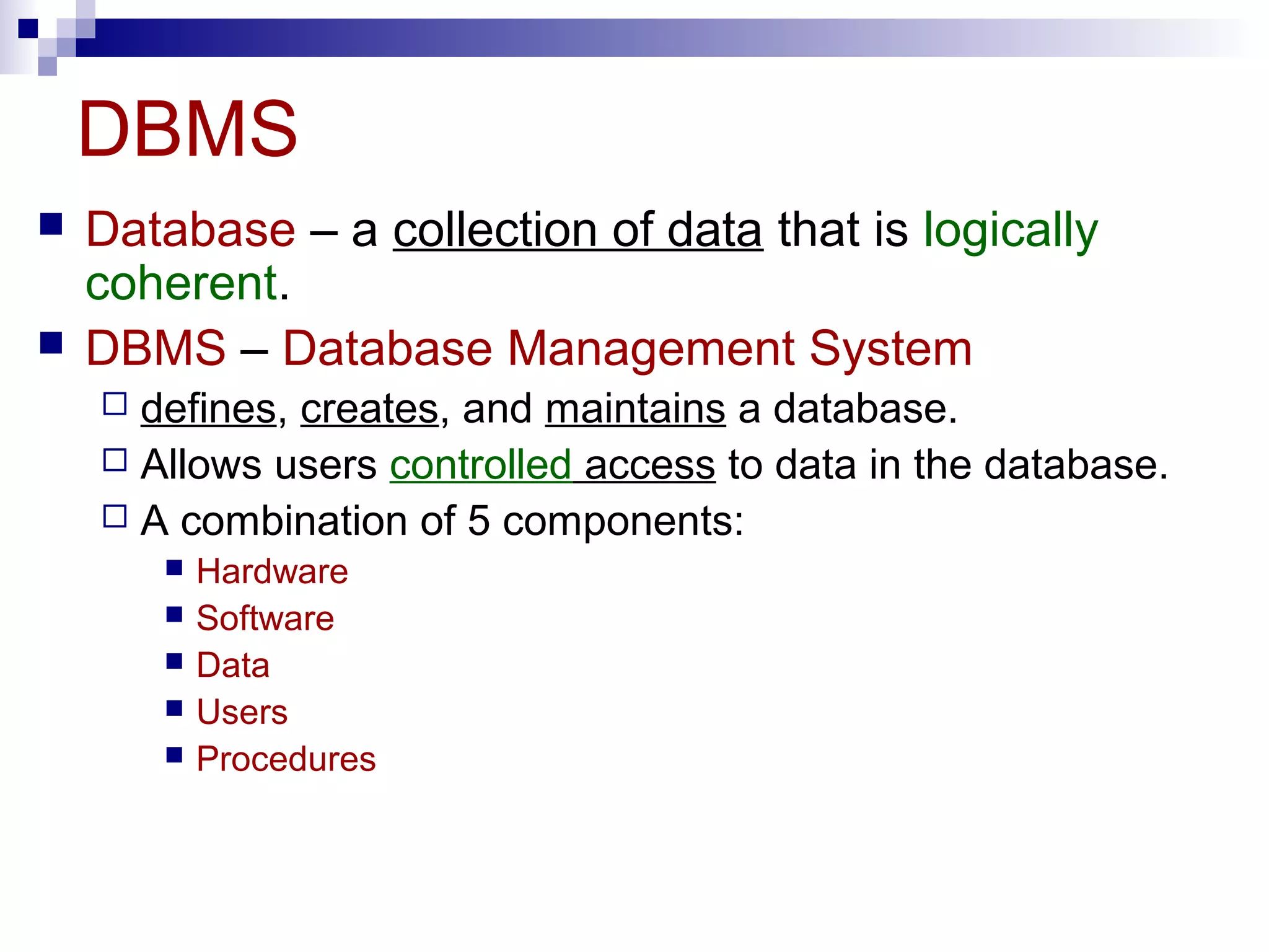
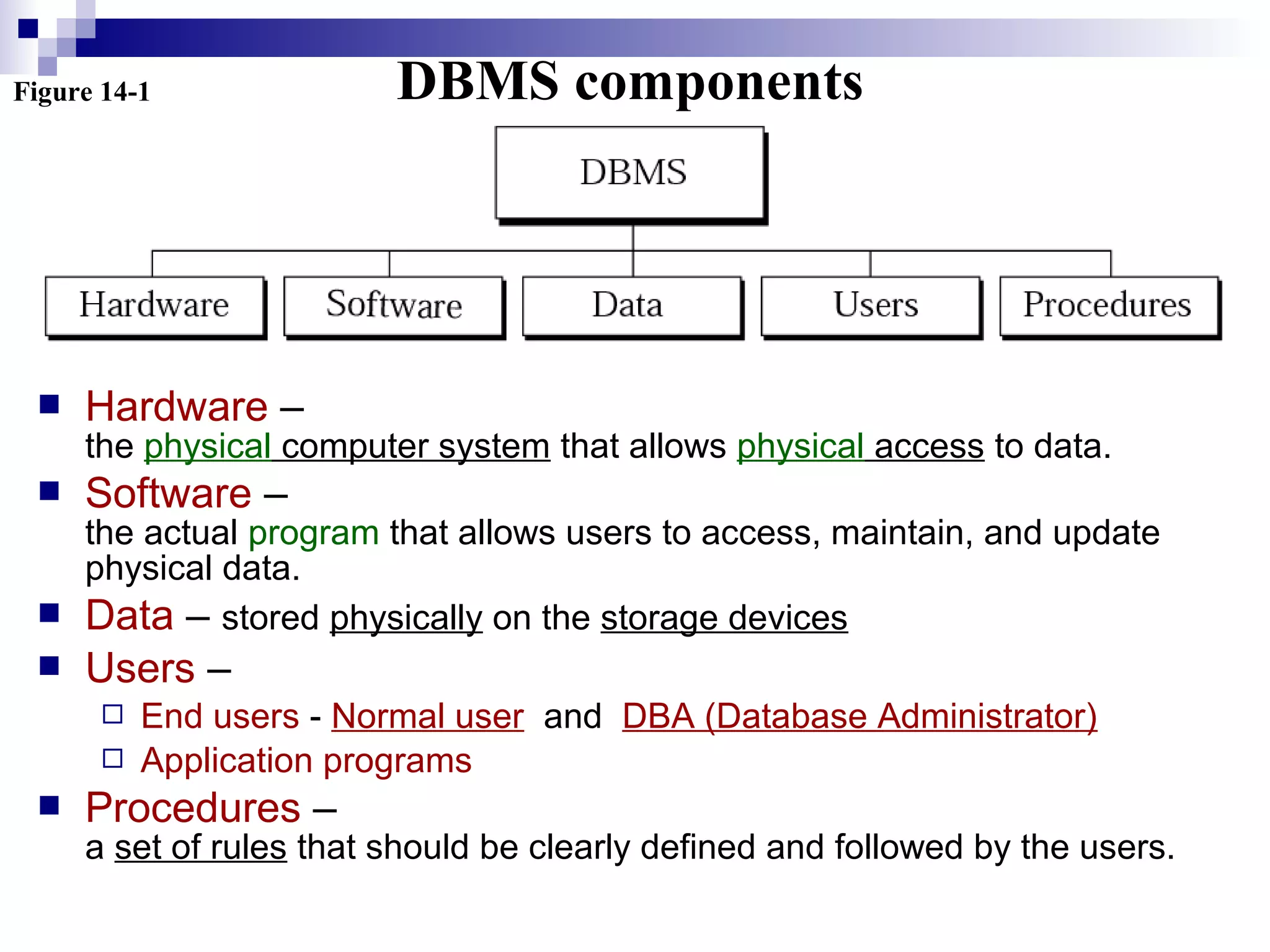
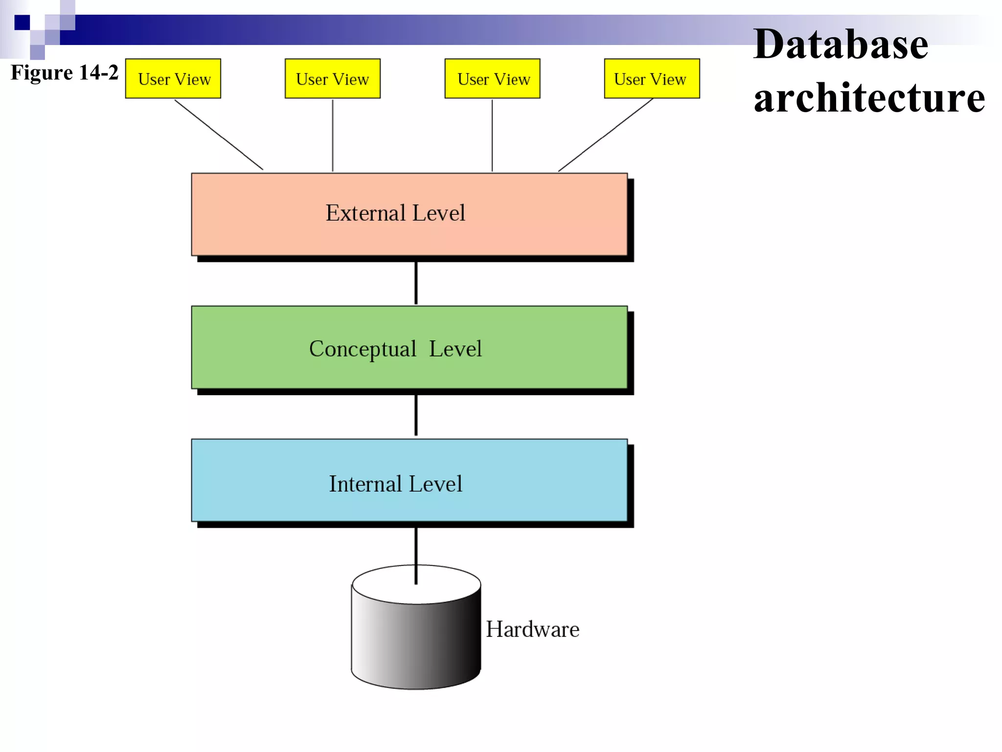
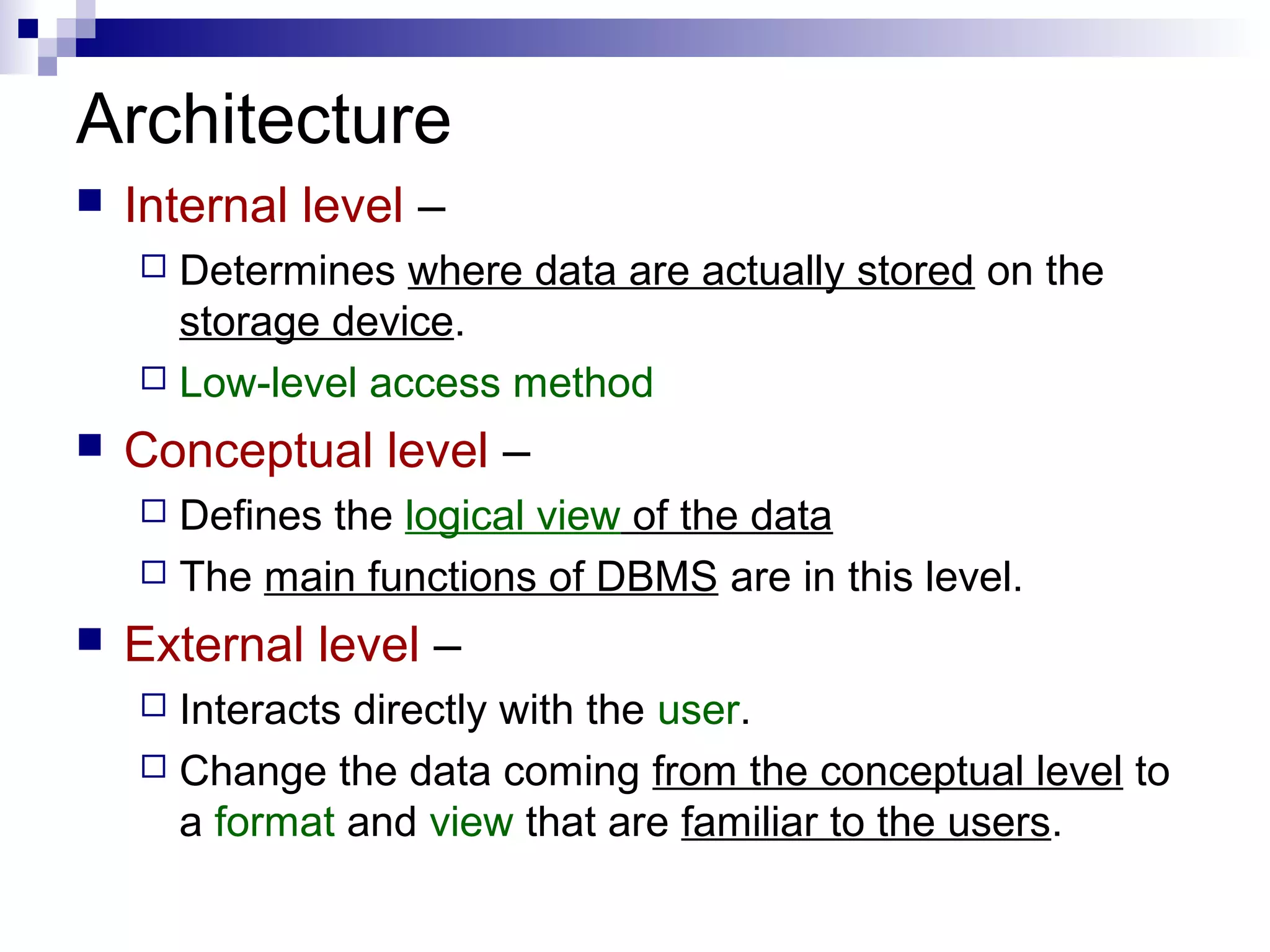
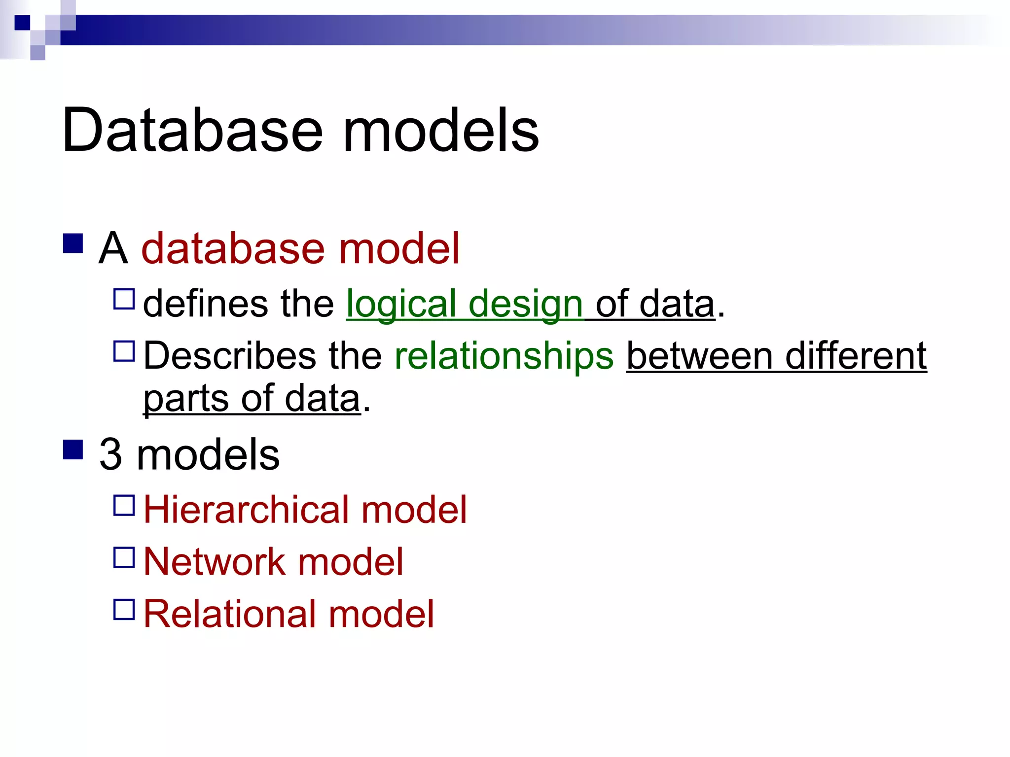
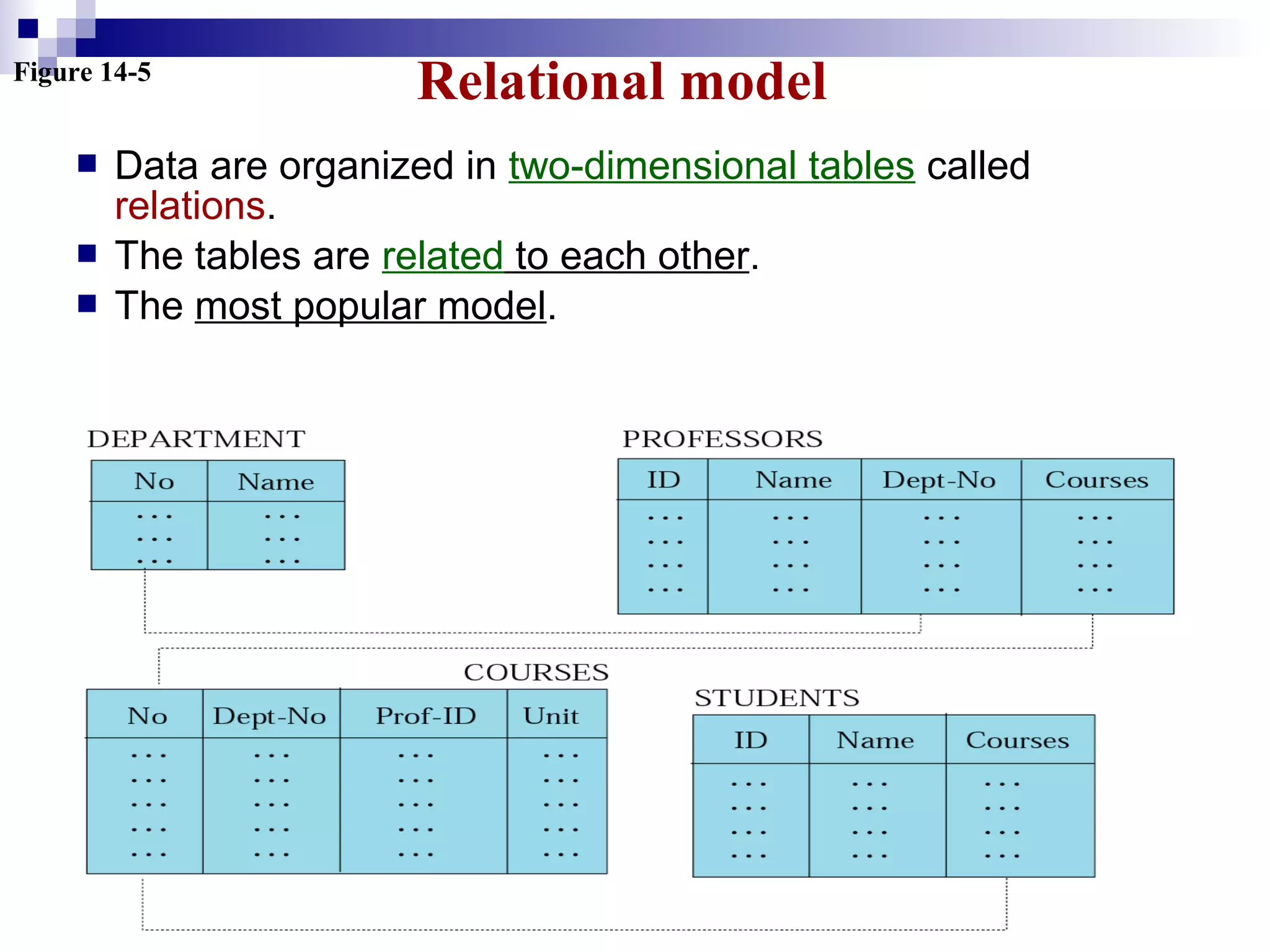
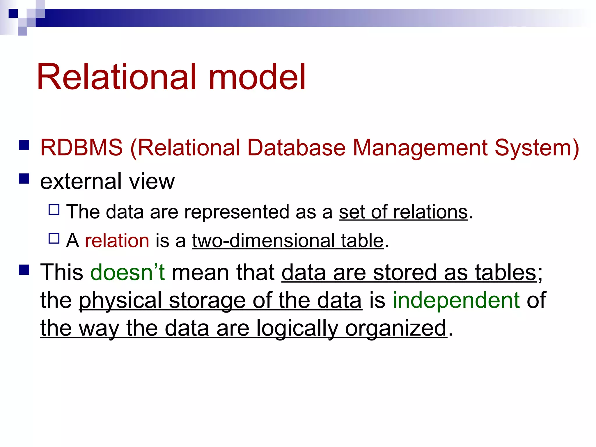
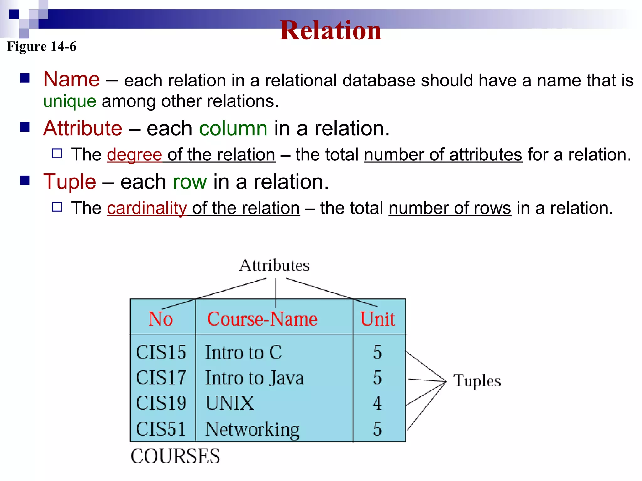
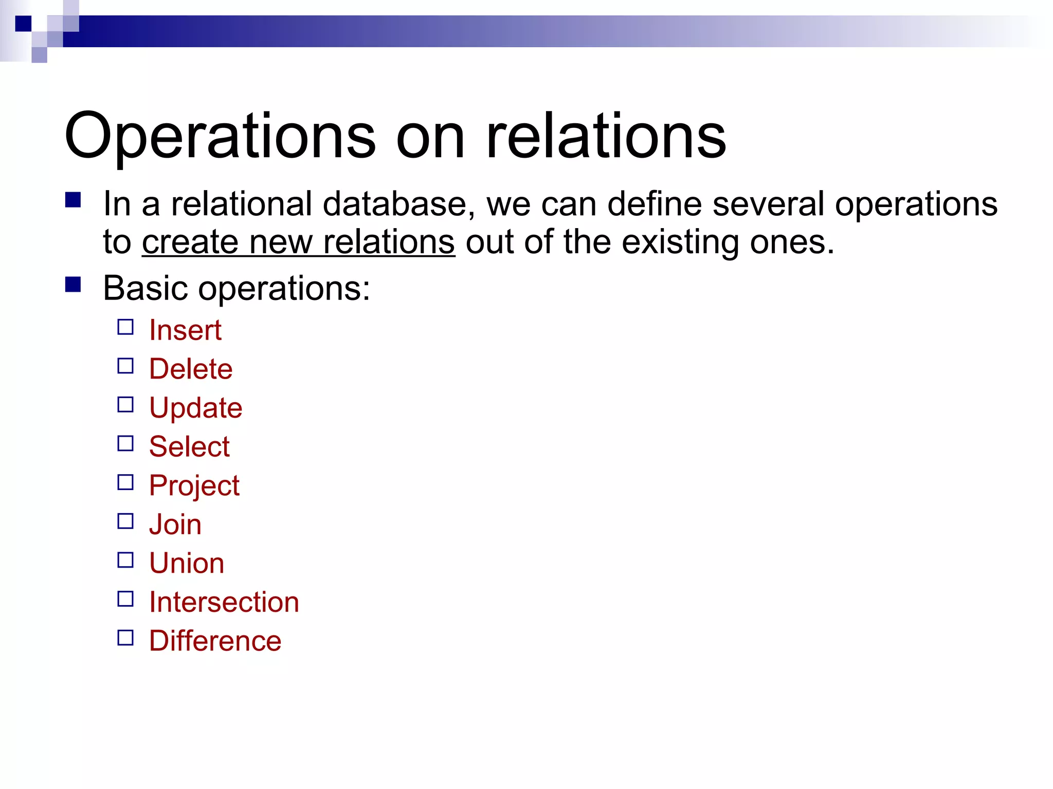
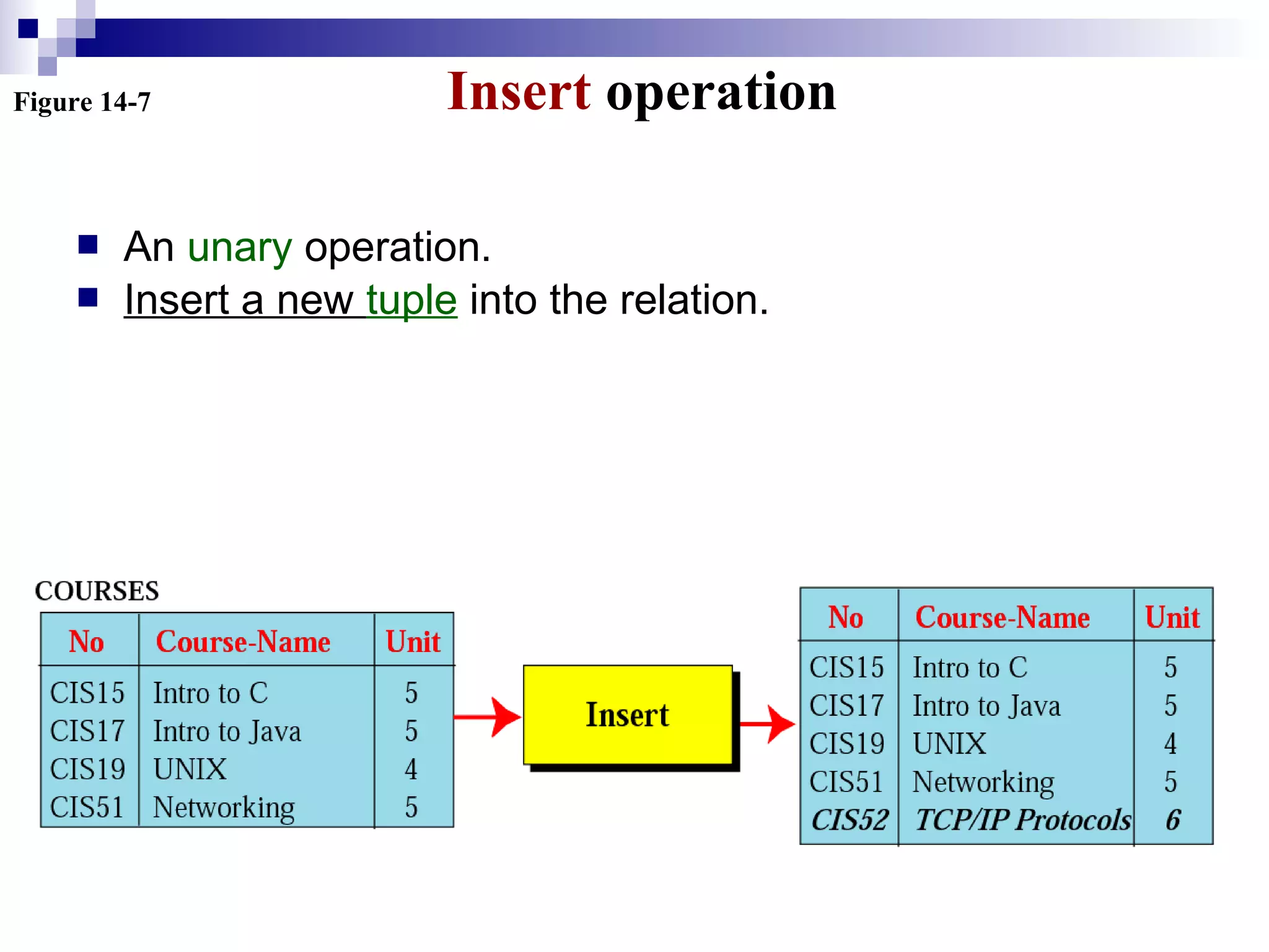
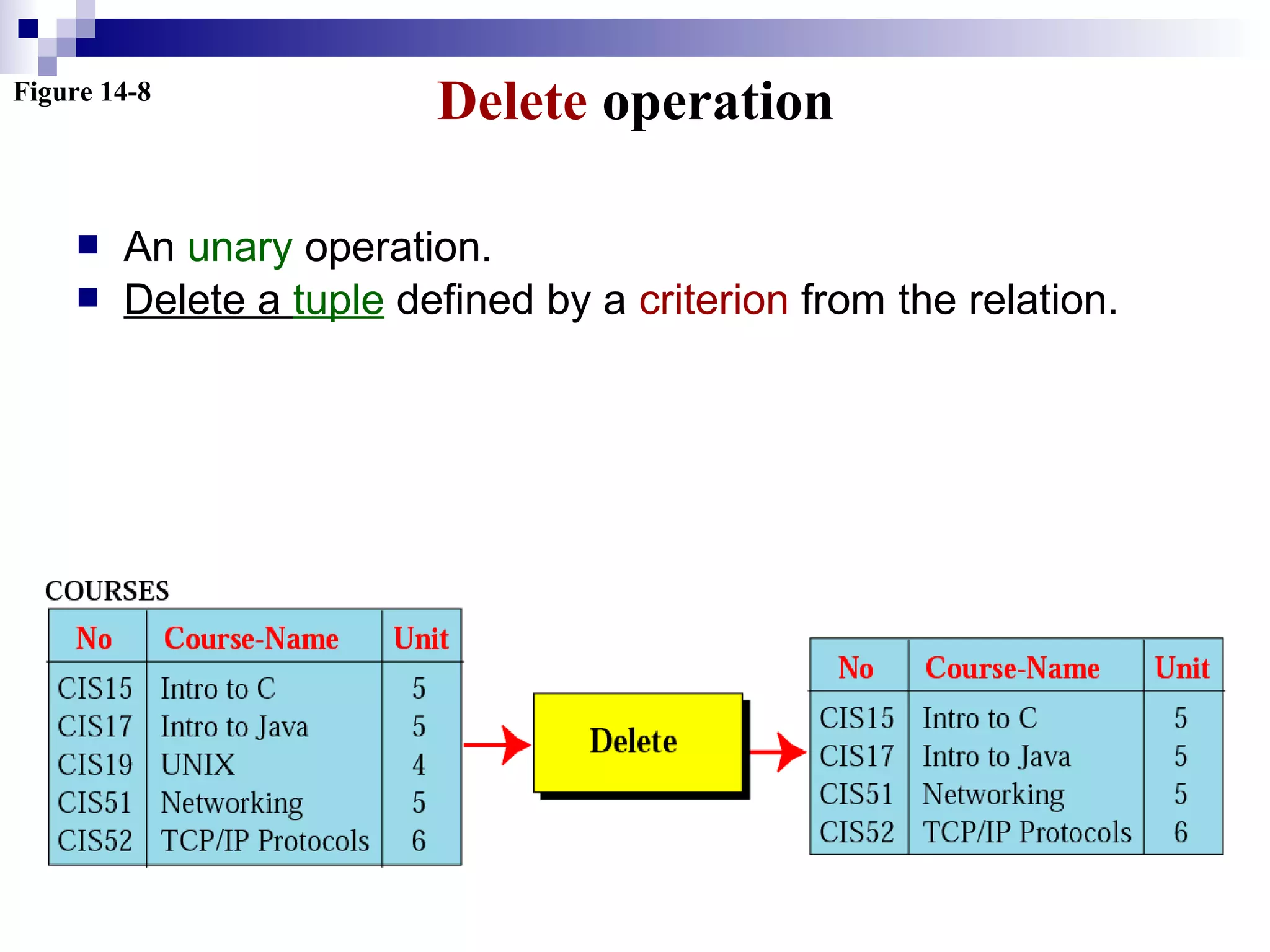
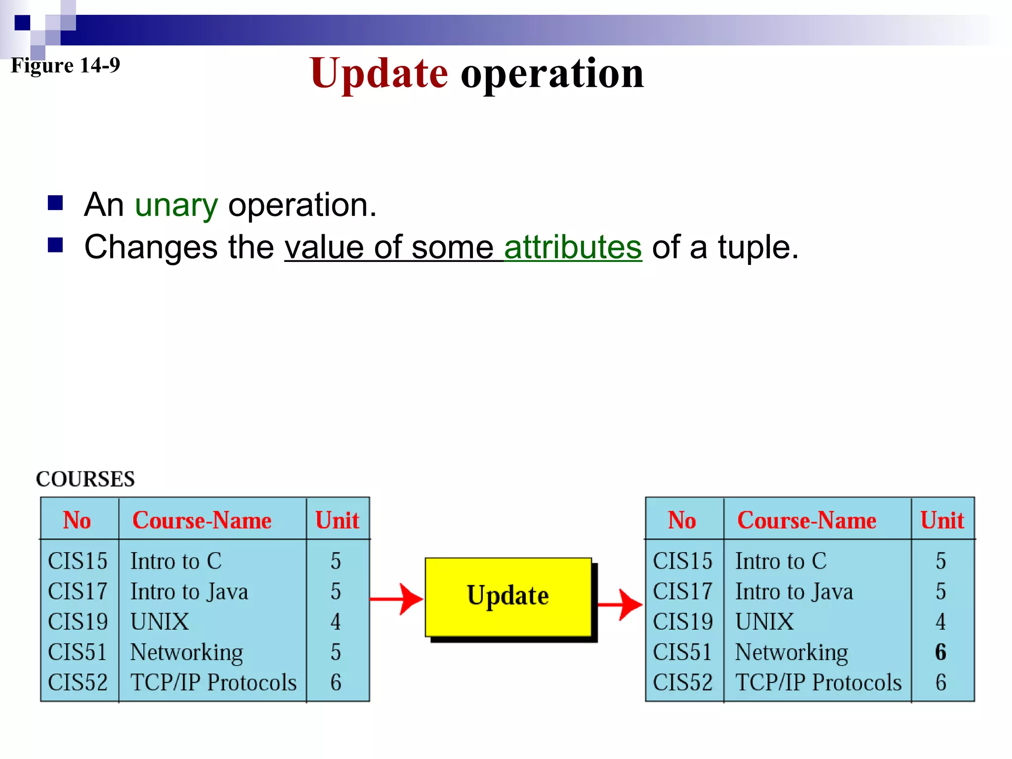
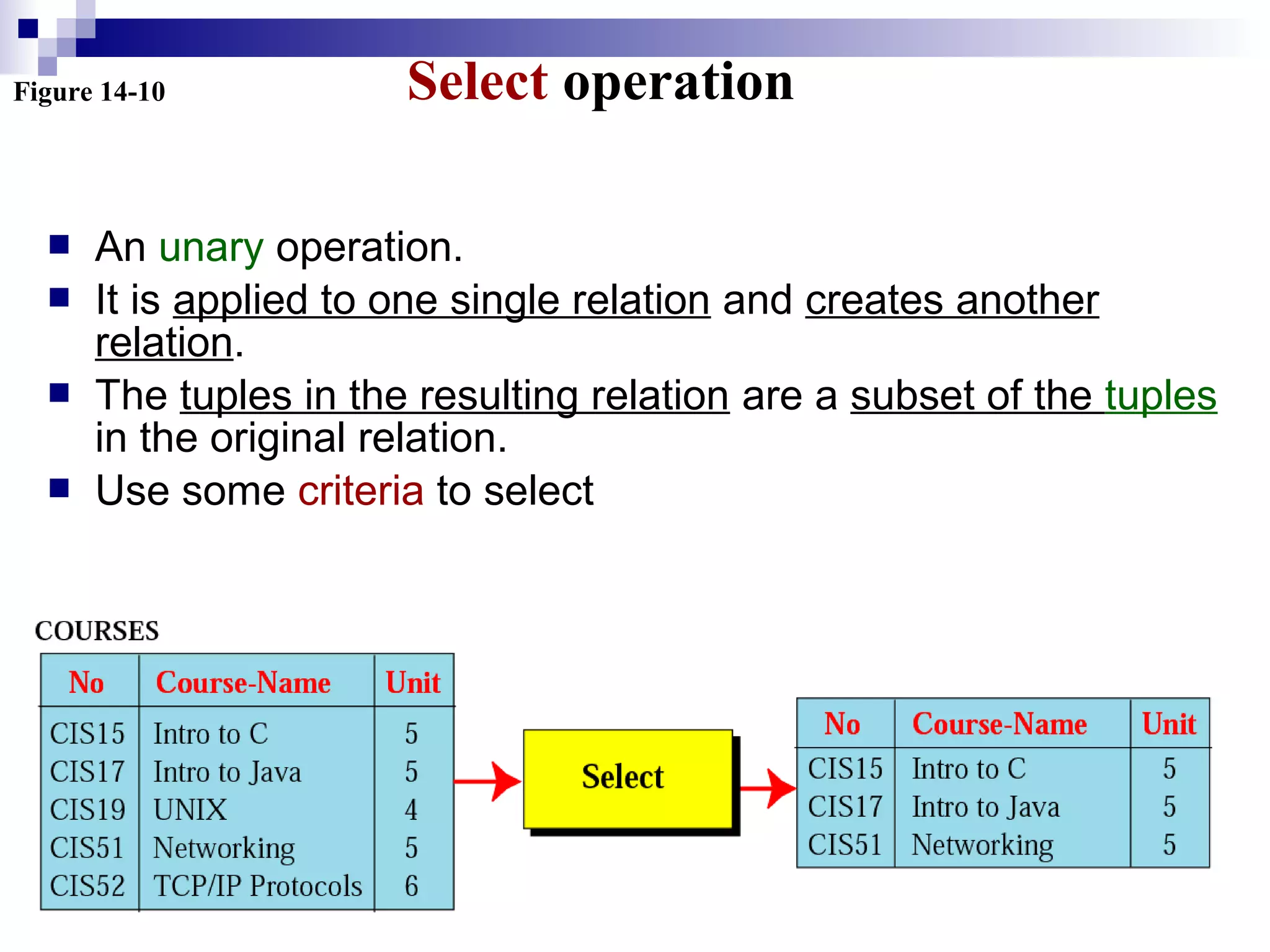
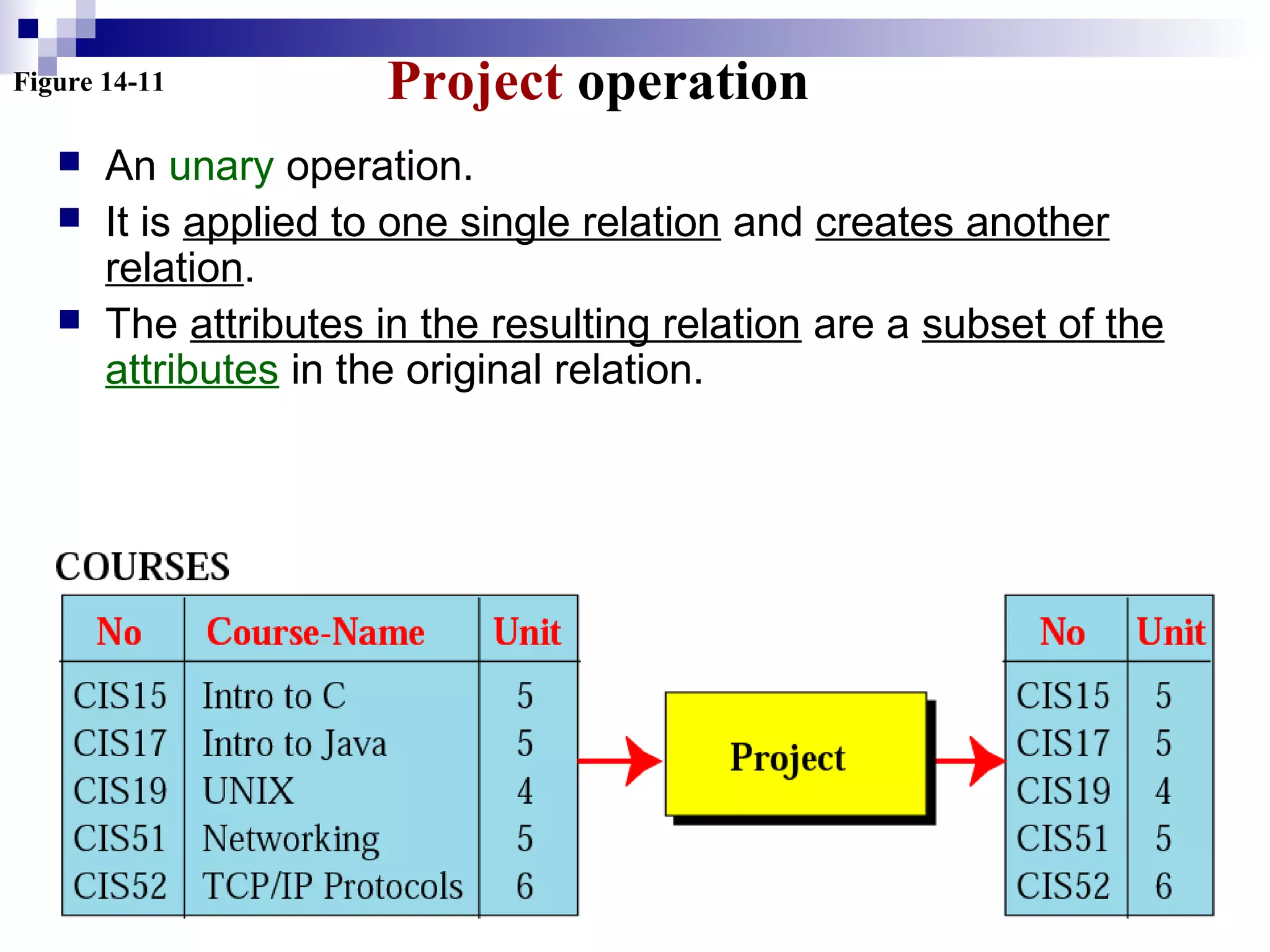
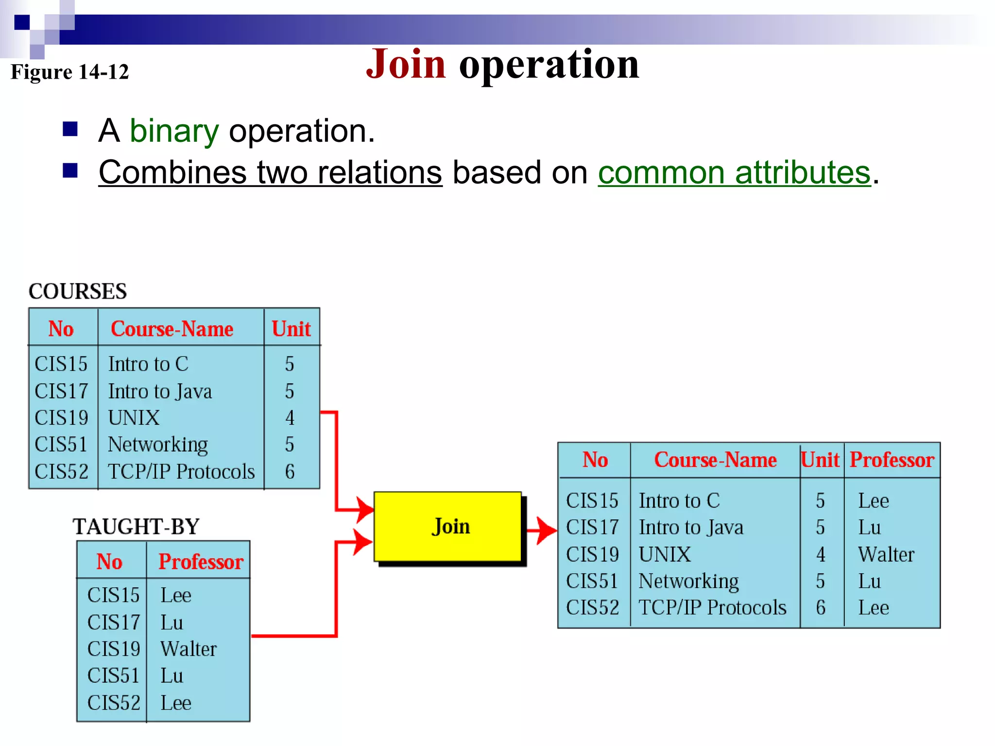
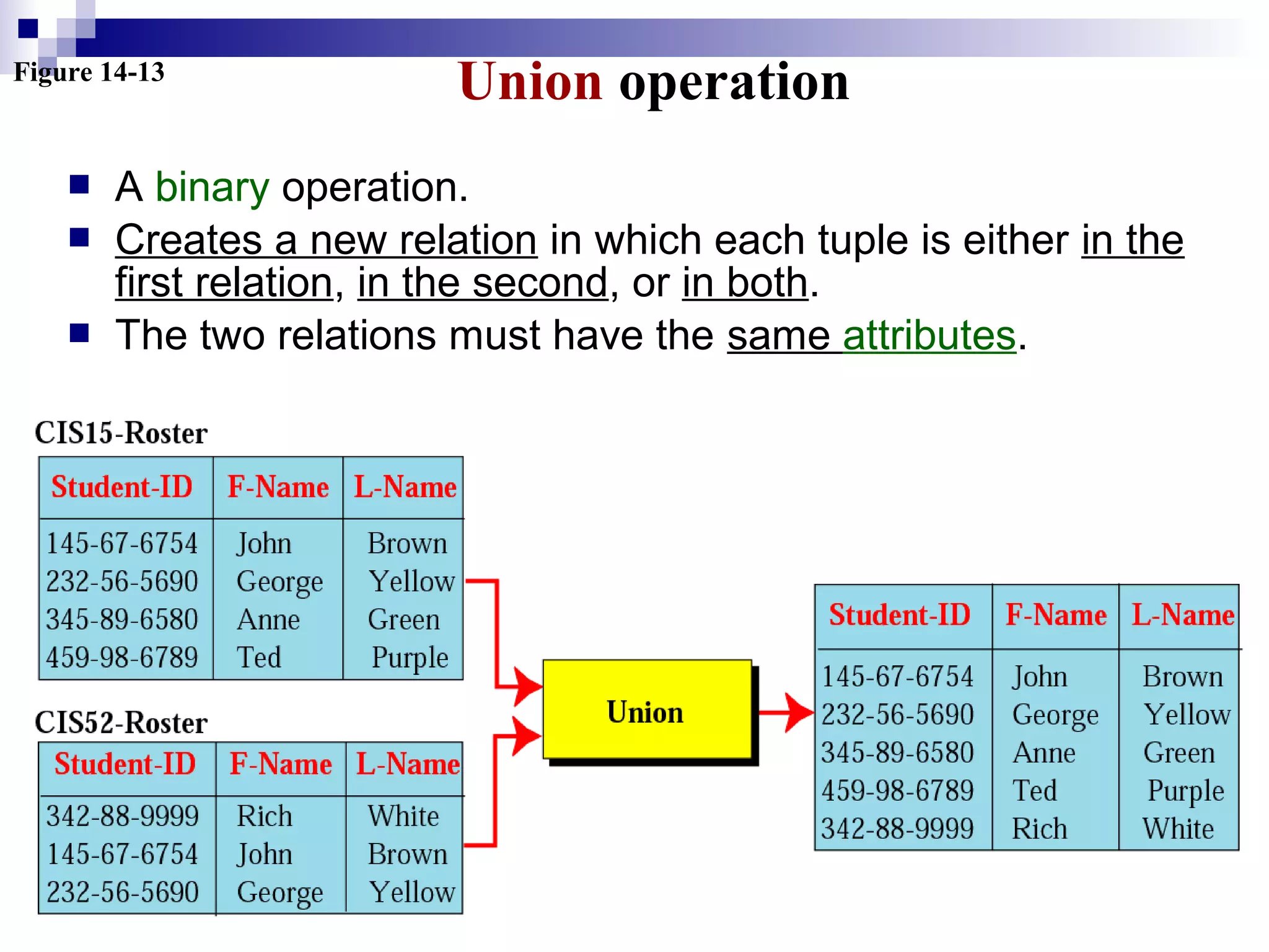
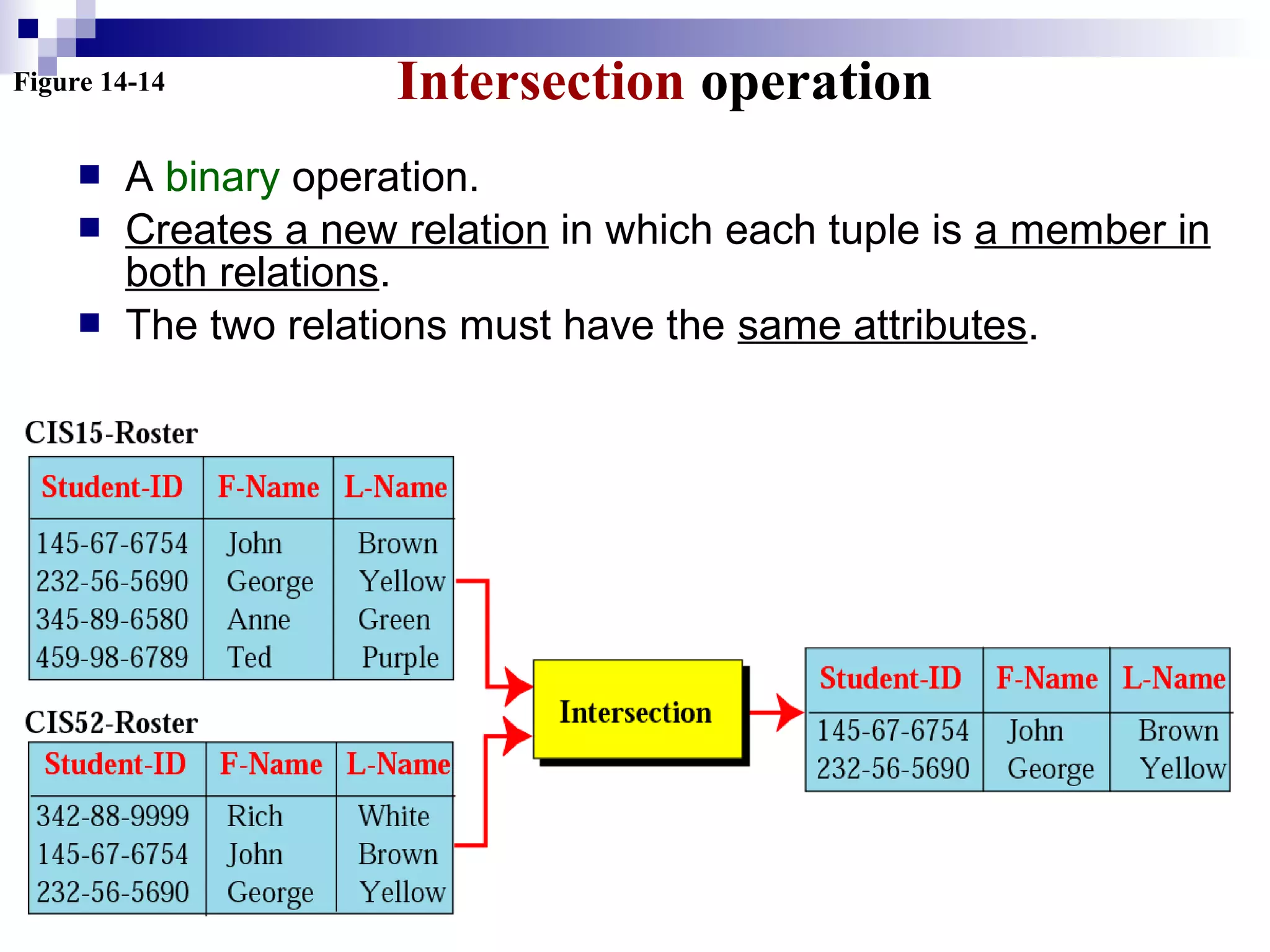
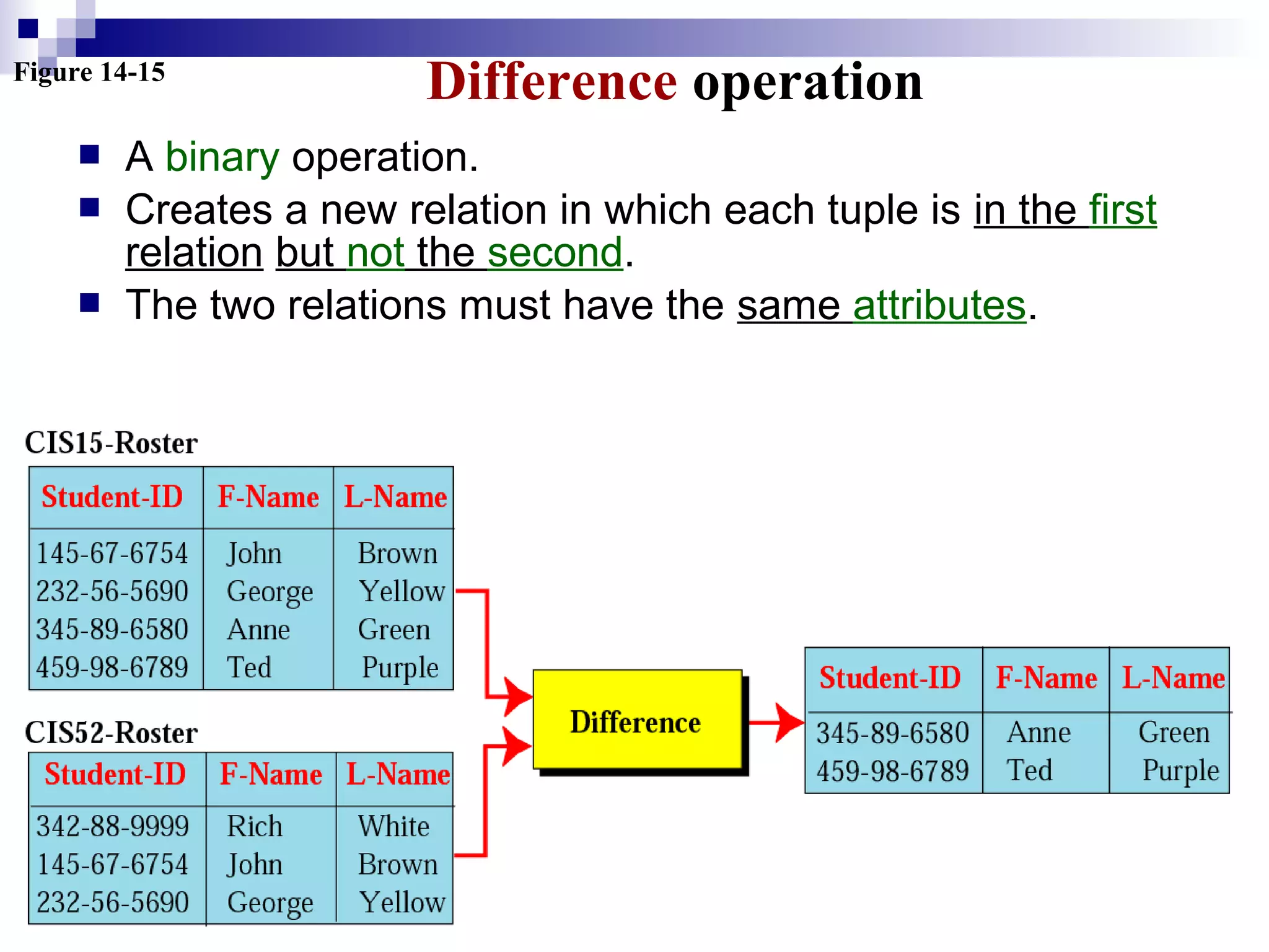
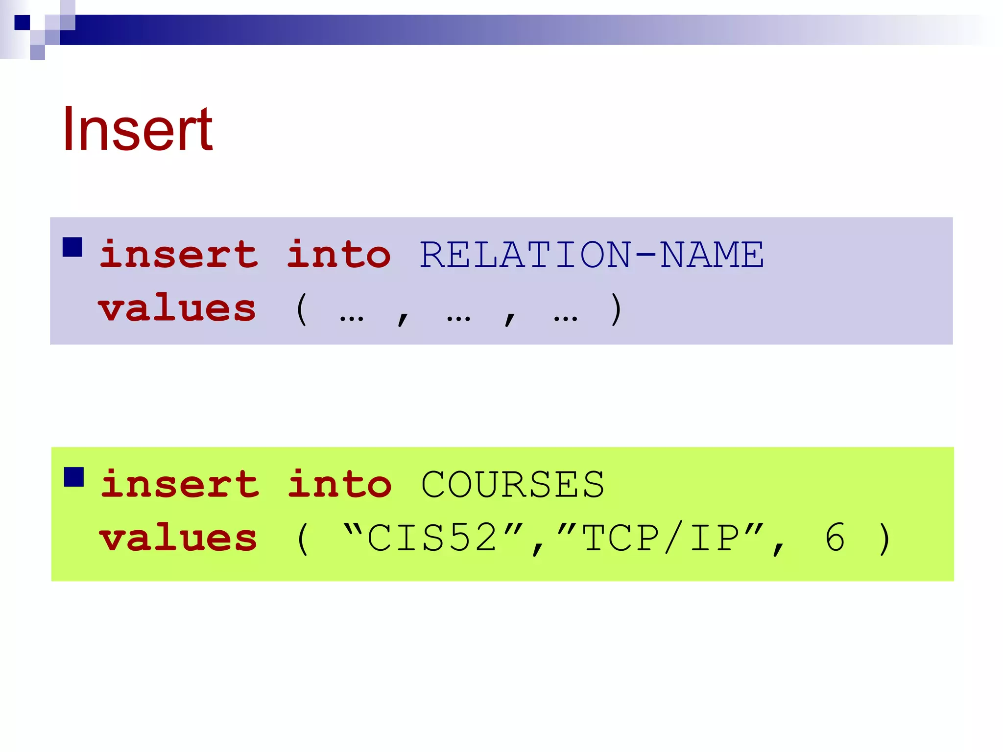
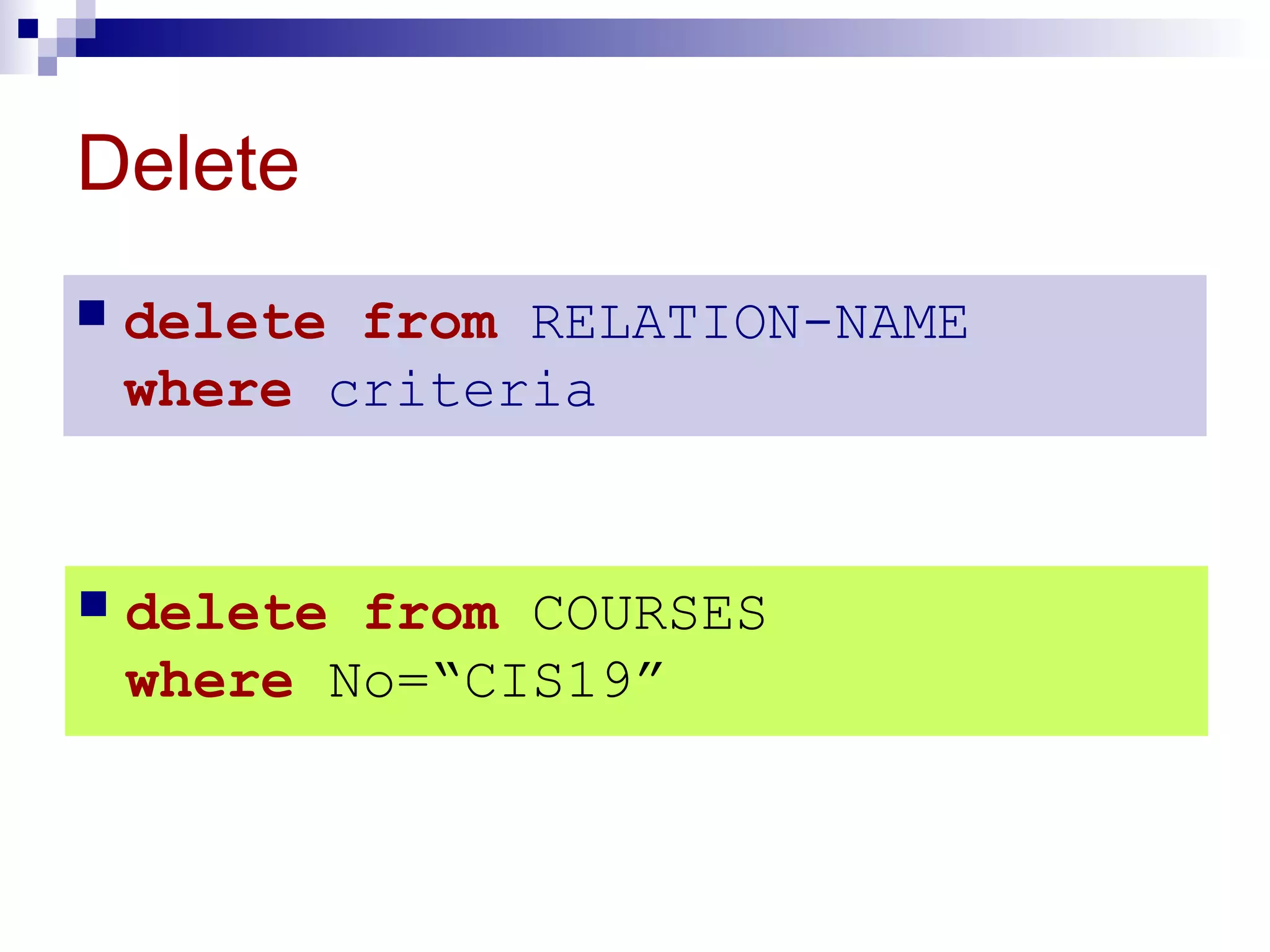
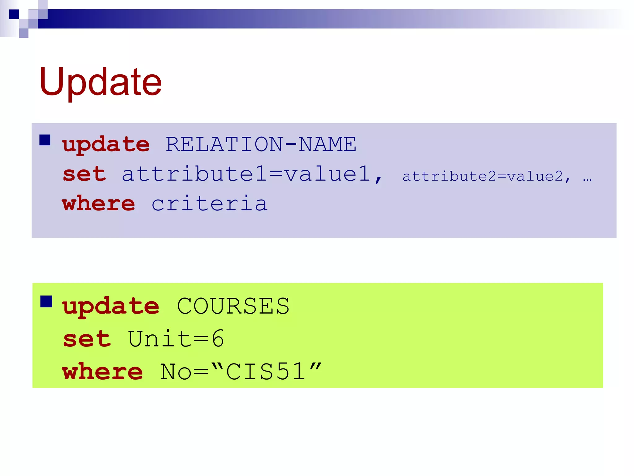
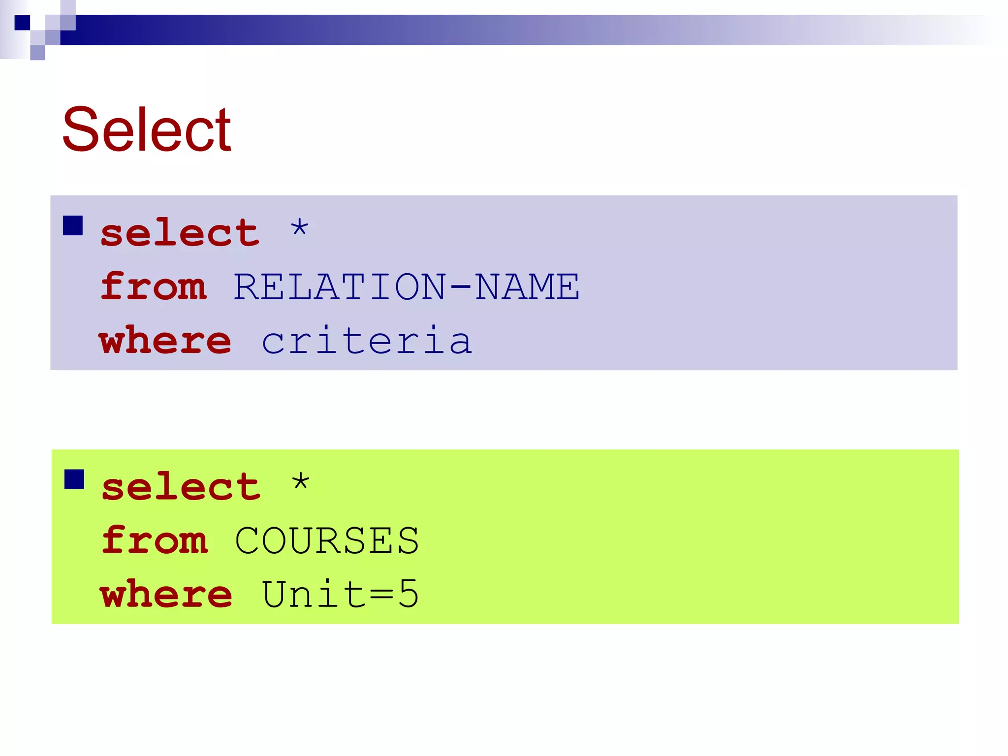
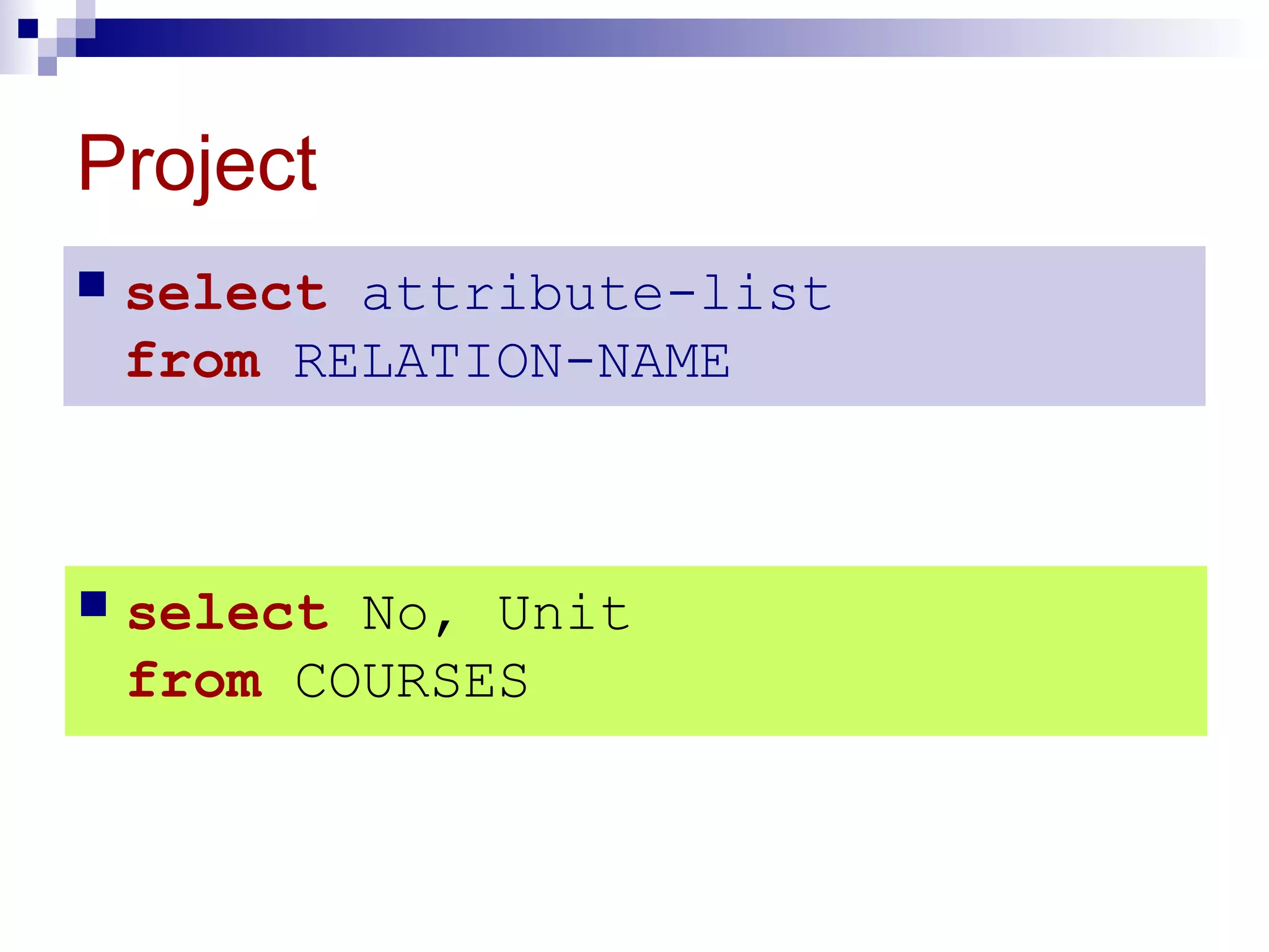
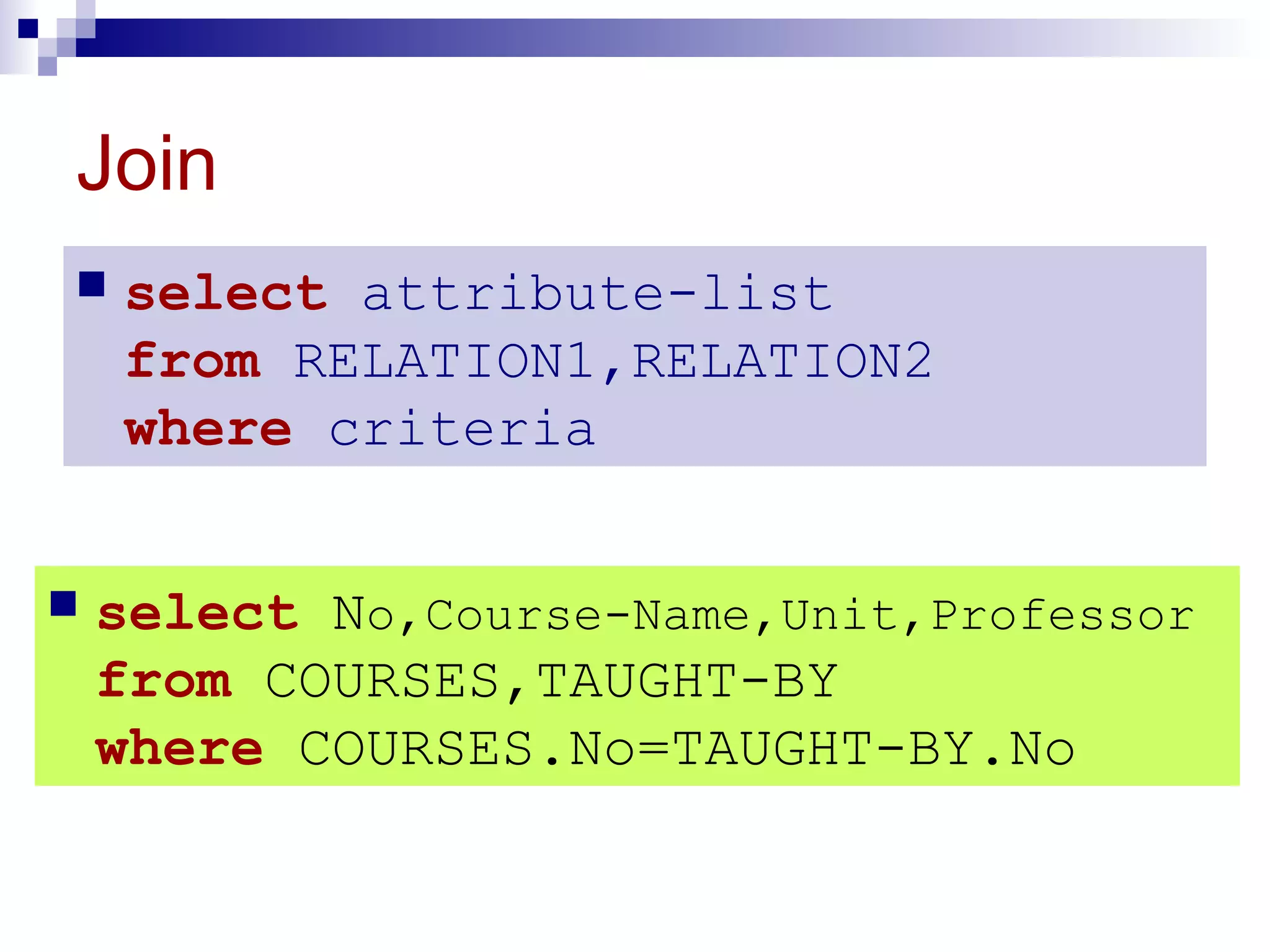
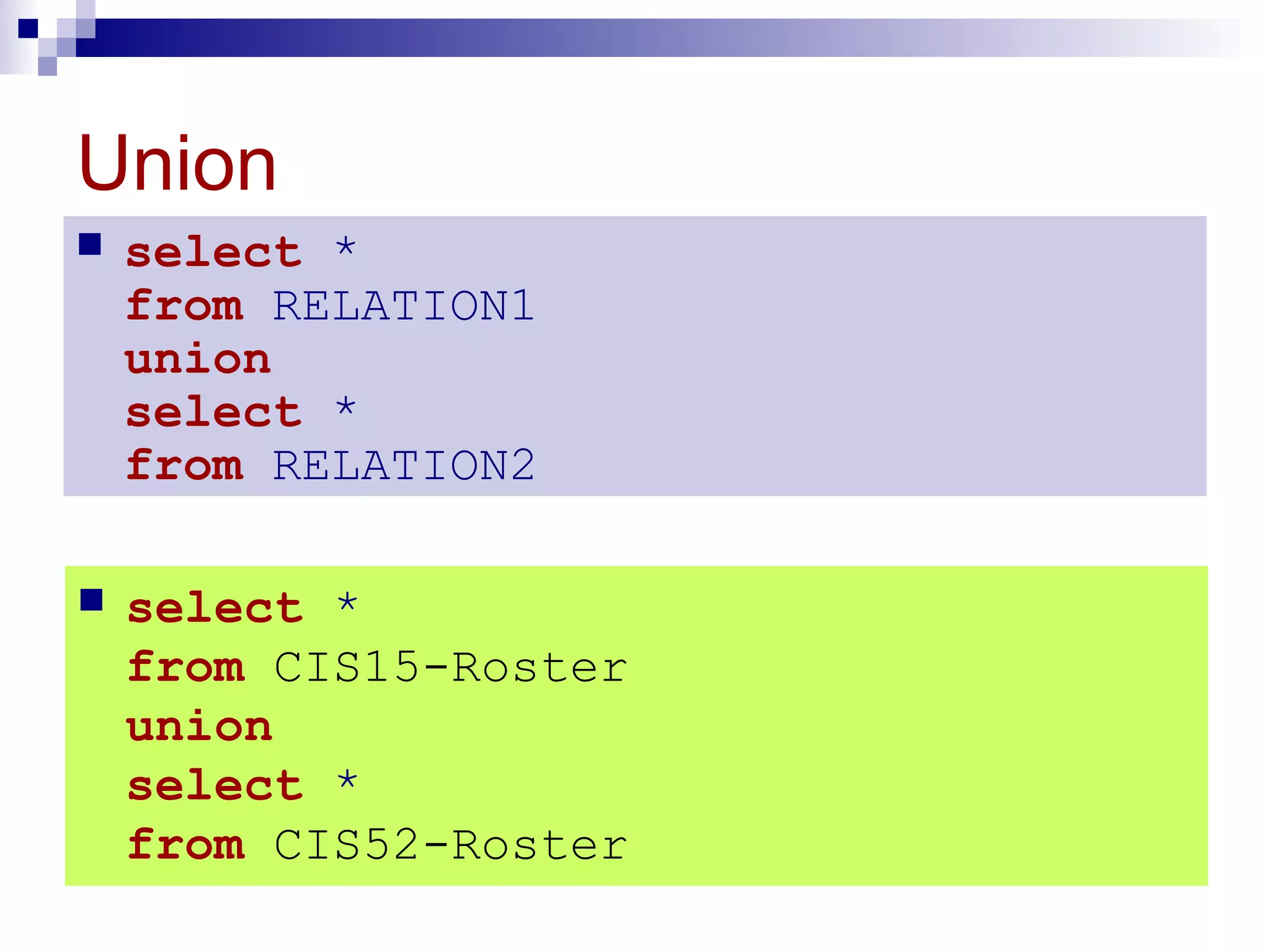
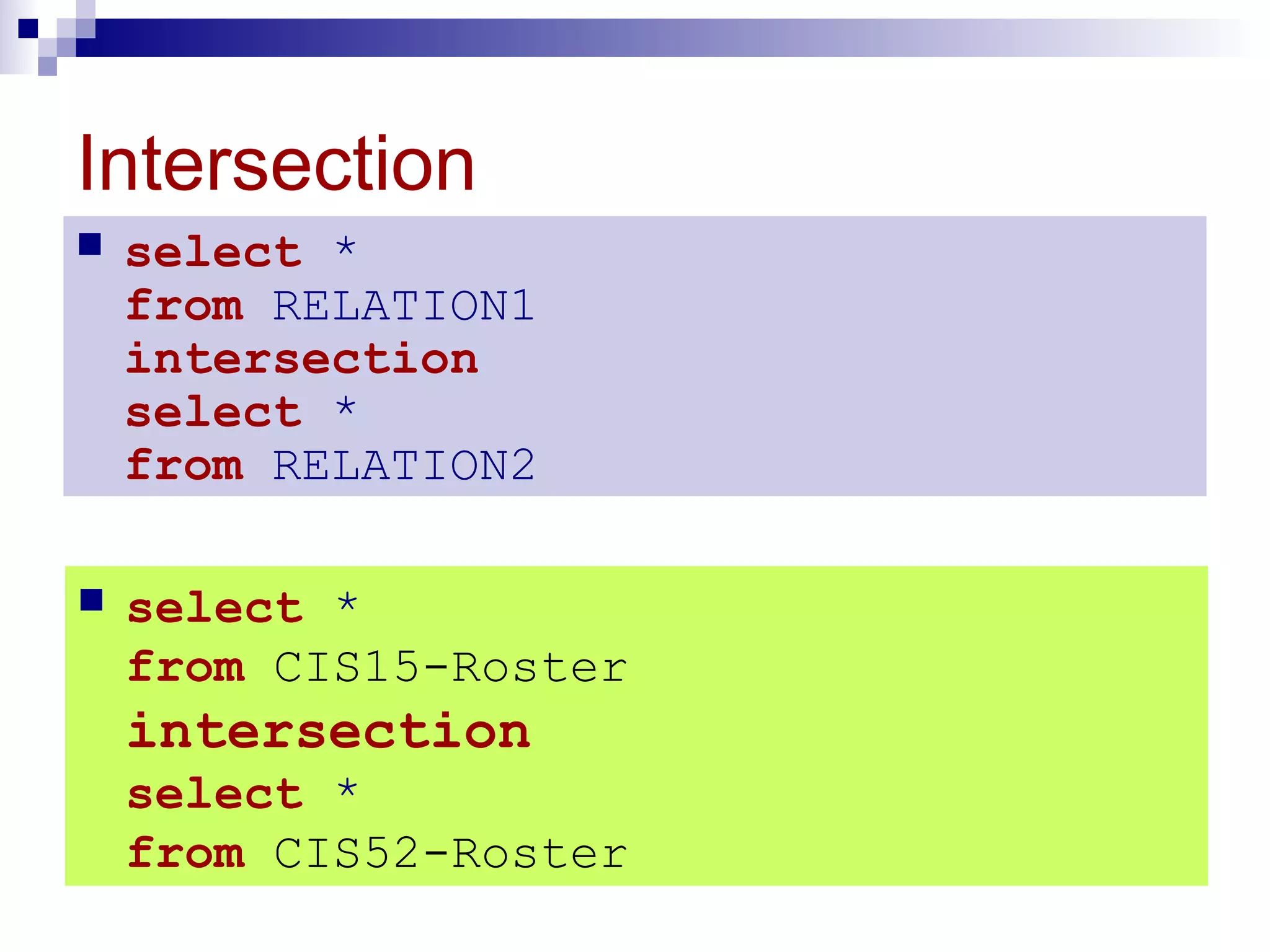
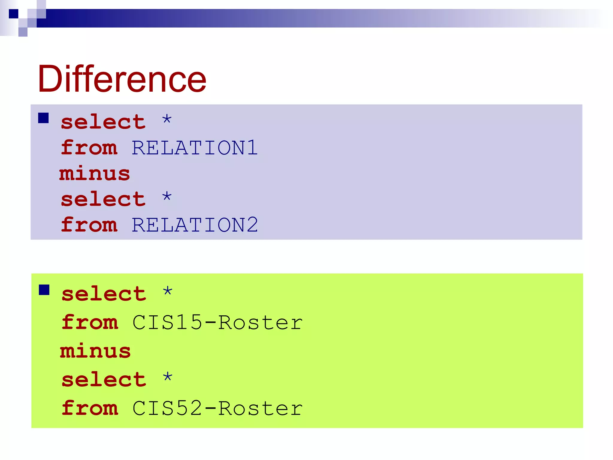
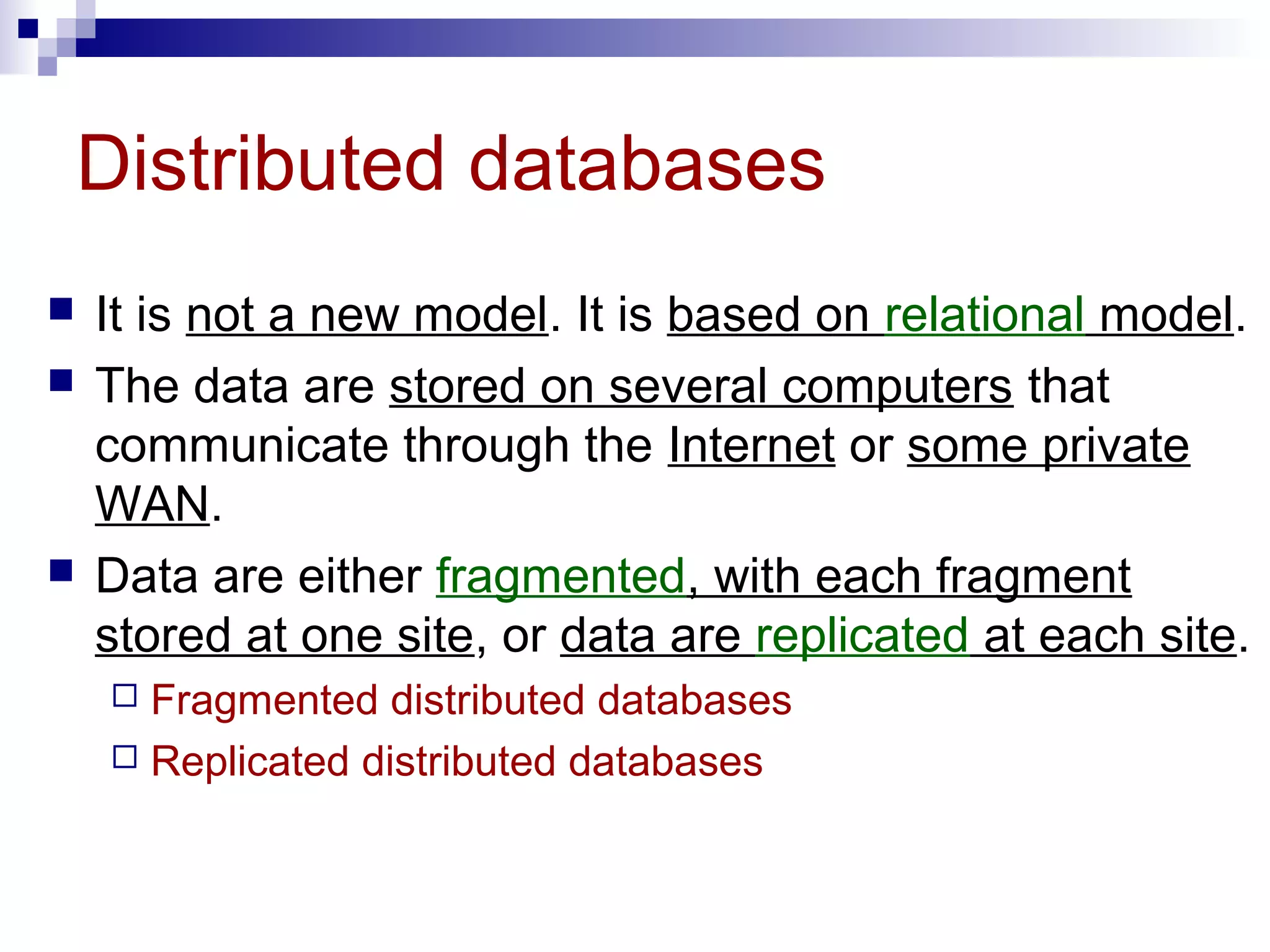
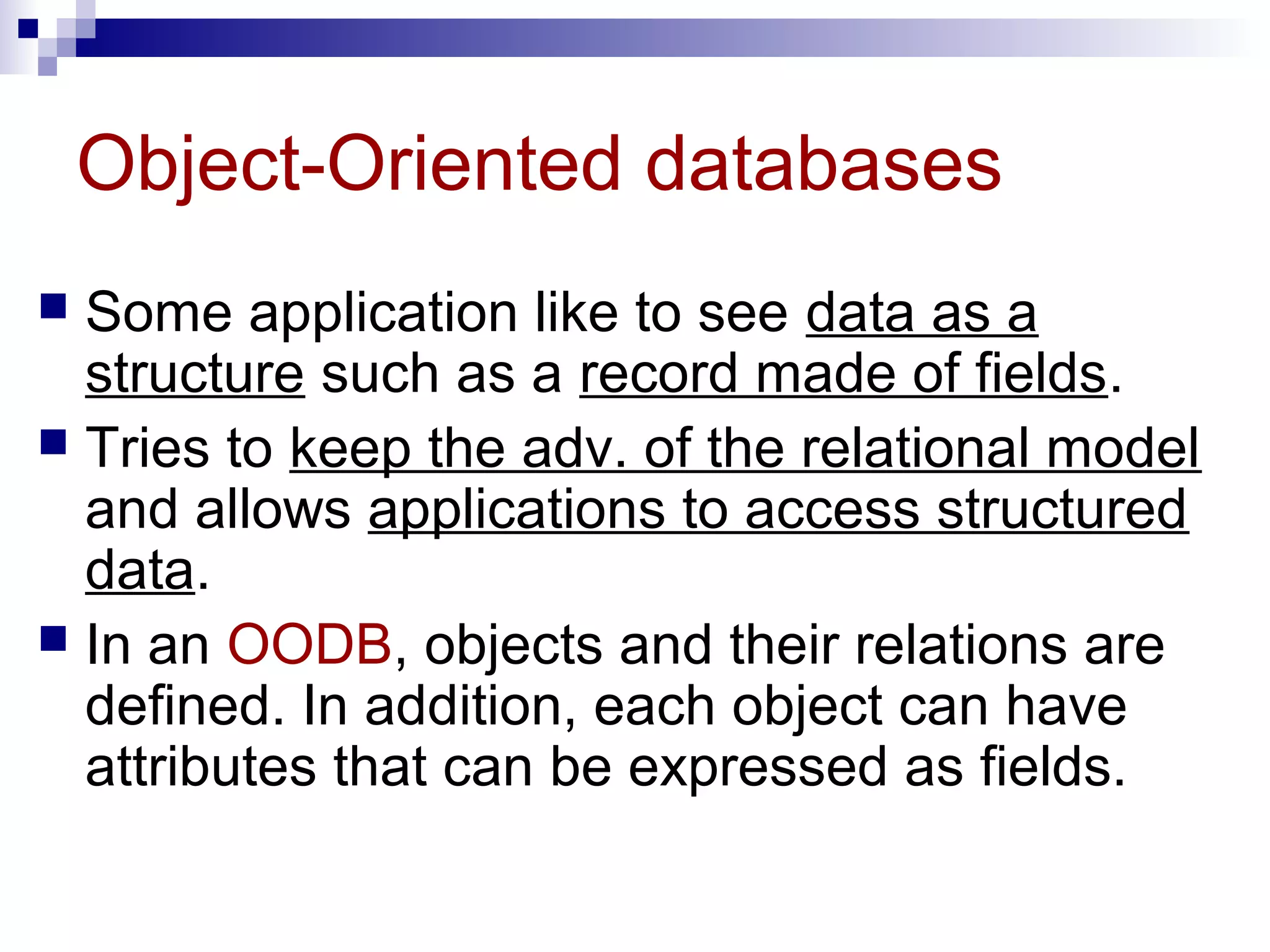
Chapter 14
Databases
Understand aUnderstand a DBMSDBMS and define its components.and define its components.
Understand the architecture of a DBMS and its levels.Understand the architecture of a DBMS and its levels.
Distinguish between differentDistinguish between different database modelsdatabase models..
Understand the concept ofUnderstand the concept of relational databaserelational database operationsoperations
on a relation.on a relation.
After reading this chapter, the reader shouldAfter reading this chapter, the reader should
be able to:be able to:
OOBJECTIVESBJECTIVES
UseUse Structured Query Language (SQL)Structured Query Language (SQL) to define simpleto define simple
relations.relations.
DATABASEDATABASE
MANAGEMENTMANAGEMENT
SYSTEMSYSTEM
14.114.1
DBMS
 Database – a collection of data that is logically
coherent.
 DBMS – Database Management System
 defines, creates, and maintains a database.
 Allows users controlled access to data in the database.
 A combination of 5 components:
 Hardware
 Software
 Data
 Users
 Procedures
Figure 14-1 DBMS components
 Hardware –
the physical computer system that allows physical access to data.
 Software –
the actual program that allows users to access, maintain, and update
physical data.
 Data – stored physically on the storage devices
 Users –
 End users - Normal user and DBA (Database Administrator)
 Application programs
 Procedures –
a set of rules that should be clearly defined and followed by the users.
ARCHITECTUREARCHITECTURE
14.214.2
Figure 14-2
Database
architecture
Architecture
 Internal level –
 Determines where data are actually stored on the
storage device.
 Low-level access method
 Conceptual level –
 Defines the logical view of the data
 The main functions of DBMS are in this level.
 External level –
 Interacts directly with the user.
 Change the data coming from the conceptual level to
a format and view that are familiar to the users.
DATABASEDATABASE
MODELSMODELS
14.314.3
Database models
 A database model
 defines the logical design of data.
 Describes the relationships between different
parts of data.
 3 models
 Hierarchical model
 Network model
 Relational model
Figure 14-3 Hierarchical model
 Data are organized as an upside down tree.
 Each entity has only one parent but can have
several children.
Figure 14-4
Network model
 The entities are organized in a graph.
 Some entities can be accessed through several
paths.
Figure 14-5
Relational model
 Data are organized in two-dimensional tables called
relations.
 The tables are related to each other.
 The most popular model.
RELATIONALRELATIONAL
MODELMODEL
14.414.4
Relational model
 RDBMS (Relational Database Management System)
 external view
 The data are represented as a set of relations.
 A relation is a two-dimensional table.
 This doesn’t mean that data are stored as tables;
the physical storage of the data is independent of
the way the data are logically organized.
Figure 14-6
Relation
 Name – each relation in a relational database should have a name that is
unique among other relations.
 Attribute – each column in a relation.
 The degree of the relation – the total number of attributes for a relation.
 Tuple – each row in a relation.
 The cardinality of the relation – the total number of rows in a relation.
OPERATIONSOPERATIONS
ONON
RELATIONSRELATIONS
14.514.5
Operations on relations
 In a relational database, we can define several operations
to create new relations out of the existing ones.
 Basic operations:
 Insert
 Delete
 Update
 Select
 Project
 Join
 Union
 Intersection
 Difference
Figure 14-7 Insert operation
 An unary operation.
 Insert a new tuple into the relation.
Figure 14-8
Delete operation
 An unary operation.
 Delete a tuple defined by a criterion from the relation.
Figure 14-9
Update operation
 An unary operation.
 Changes the value of some attributes of a tuple.
Figure 14-10 Select operation
 An unary operation.
 It is applied to one single relation and creates another
relation.
 The tuples in the resulting relation are a subset of the tuples
in the original relation.
 Use some criteria to select
Figure 14-11 Project operation
 An unary operation.
 It is applied to one single relation and creates another
relation.
 The attributes in the resulting relation are a subset of the
attributes in the original relation.
Figure 14-12 Join operation
 A binary operation.
 Combines two relations based on common attributes.
Figure 14-13
Union operation
 A binary operation.
 Creates a new relation in which each tuple is either in the
first relation, in the second, or in both.
 The two relations must have the same attributes.
Figure 14-14 Intersection operation
 A binary operation.
 Creates a new relation in which each tuple is a member in
both relations.
 The two relations must have the same attributes.
Figure 14-15
Difference operation
 A binary operation.
 Creates a new relation in which each tuple is in the first
relation but not the second.
 The two relations must have the same attributes.
STRUCTUREDSTRUCTURED
QUERYQUERY
LANGUAGELANGUAGE
14.614.6
SQL (Structured Query Language)
 Standardized by ANSI and ISO for use on
relational databases.
 It is a declarative (not procedural) language,
which means that the users declare what they
want without having to write a step-by-step
procedure.
 First implemented by Oracle in 1979.
 SQL allows you to combine the following
statements to extract more complex information
from database.
Insert
 insert into RELATION-NAME
values ( … , … , … )
 insert into COURSES
values ( “CIS52”,”TCP/IP”, 6 )
Delete
 delete from RELATION-NAME
where criteria
 delete from COURSES
where No=“CIS19”
Update
 update RELATION-NAME
set attribute1=value1, attribute2=value2, …
where criteria
 update COURSES
set Unit=6
where No=“CIS51”
Select
 select *
from RELATION-NAME
where criteria
 select *
from COURSES
where Unit=5
Project
 select attribute-list
from RELATION-NAME
 select No, Unit
from COURSES
Join
 select attribute-list
from RELATION1,RELATION2
where criteria
 select No,Course-Name,Unit,Professor
from COURSES,TAUGHT-BY
where COURSES.No=TAUGHT-BY.No
Union
 select *
from RELATION1
union
select *
from RELATION2
 select *
from CIS15-Roster
union
select *
from CIS52-Roster
Intersection
 select *
from RELATION1
intersection
select *
from RELATION2
 select *
from CIS15-Roster
intersection
select *
from CIS52-Roster
Difference
 select *
from RELATION1
minus
select *
from RELATION2
 select *
from CIS15-Roster
minus
select *
from CIS52-Roster
OTHEROTHER
DATABASEDATABASE
MODELSMODELS
14.714.7
Distributed databases
 It is not a new model. It is based on relational model.
 The data are stored on several computers that
communicate through the Internet or some private
WAN.
 Data are either fragmented, with each fragment
stored at one site, or data are replicated at each site.
 Fragmented distributed databases
 Replicated distributed databases
Object-Oriented databases
 Some application like to see data as a
structure such as a record made of fields.
 Tries to keep the adv. of the relational model
and allows applications to access structured
data.
 In an OODB, objects and their relations are
defined. In addition, each object can have
attributes that can be expressed as fields.

21792 relational database managementsystem

  • 1.
  • 2.
    Understand aUnderstand aDBMSDBMS and define its components.and define its components. Understand the architecture of a DBMS and its levels.Understand the architecture of a DBMS and its levels. Distinguish between differentDistinguish between different database modelsdatabase models.. Understand the concept ofUnderstand the concept of relational databaserelational database operationsoperations on a relation.on a relation. After reading this chapter, the reader shouldAfter reading this chapter, the reader should be able to:be able to: OOBJECTIVESBJECTIVES UseUse Structured Query Language (SQL)Structured Query Language (SQL) to define simpleto define simple relations.relations.
  • 3.
  • 4.
    DBMS  Database –a collection of data that is logically coherent.  DBMS – Database Management System  defines, creates, and maintains a database.  Allows users controlled access to data in the database.  A combination of 5 components:  Hardware  Software  Data  Users  Procedures
  • 5.
    Figure 14-1 DBMScomponents  Hardware – the physical computer system that allows physical access to data.  Software – the actual program that allows users to access, maintain, and update physical data.  Data – stored physically on the storage devices  Users –  End users - Normal user and DBA (Database Administrator)  Application programs  Procedures – a set of rules that should be clearly defined and followed by the users.
  • 6.
  • 7.
  • 8.
    Architecture  Internal level–  Determines where data are actually stored on the storage device.  Low-level access method  Conceptual level –  Defines the logical view of the data  The main functions of DBMS are in this level.  External level –  Interacts directly with the user.  Change the data coming from the conceptual level to a format and view that are familiar to the users.
  • 9.
  • 10.
    Database models  Adatabase model  defines the logical design of data.  Describes the relationships between different parts of data.  3 models  Hierarchical model  Network model  Relational model
  • 11.
    Figure 14-3 Hierarchicalmodel  Data are organized as an upside down tree.  Each entity has only one parent but can have several children.
  • 12.
    Figure 14-4 Network model The entities are organized in a graph.  Some entities can be accessed through several paths.
  • 13.
    Figure 14-5 Relational model Data are organized in two-dimensional tables called relations.  The tables are related to each other.  The most popular model.
  • 14.
  • 15.
    Relational model  RDBMS(Relational Database Management System)  external view  The data are represented as a set of relations.  A relation is a two-dimensional table.  This doesn’t mean that data are stored as tables; the physical storage of the data is independent of the way the data are logically organized.
  • 16.
    Figure 14-6 Relation  Name– each relation in a relational database should have a name that is unique among other relations.  Attribute – each column in a relation.  The degree of the relation – the total number of attributes for a relation.  Tuple – each row in a relation.  The cardinality of the relation – the total number of rows in a relation.
  • 17.
  • 18.
    Operations on relations In a relational database, we can define several operations to create new relations out of the existing ones.  Basic operations:  Insert  Delete  Update  Select  Project  Join  Union  Intersection  Difference
  • 19.
    Figure 14-7 Insertoperation  An unary operation.  Insert a new tuple into the relation.
  • 20.
    Figure 14-8 Delete operation An unary operation.  Delete a tuple defined by a criterion from the relation.
  • 21.
    Figure 14-9 Update operation An unary operation.  Changes the value of some attributes of a tuple.
  • 22.
    Figure 14-10 Selectoperation  An unary operation.  It is applied to one single relation and creates another relation.  The tuples in the resulting relation are a subset of the tuples in the original relation.  Use some criteria to select
  • 23.
    Figure 14-11 Projectoperation  An unary operation.  It is applied to one single relation and creates another relation.  The attributes in the resulting relation are a subset of the attributes in the original relation.
  • 24.
    Figure 14-12 Joinoperation  A binary operation.  Combines two relations based on common attributes.
  • 25.
    Figure 14-13 Union operation A binary operation.  Creates a new relation in which each tuple is either in the first relation, in the second, or in both.  The two relations must have the same attributes.
  • 26.
    Figure 14-14 Intersectionoperation  A binary operation.  Creates a new relation in which each tuple is a member in both relations.  The two relations must have the same attributes.
  • 27.
    Figure 14-15 Difference operation A binary operation.  Creates a new relation in which each tuple is in the first relation but not the second.  The two relations must have the same attributes.
  • 28.
  • 29.
    SQL (Structured QueryLanguage)  Standardized by ANSI and ISO for use on relational databases.  It is a declarative (not procedural) language, which means that the users declare what they want without having to write a step-by-step procedure.  First implemented by Oracle in 1979.  SQL allows you to combine the following statements to extract more complex information from database.
  • 30.
    Insert  insert intoRELATION-NAME values ( … , … , … )  insert into COURSES values ( “CIS52”,”TCP/IP”, 6 )
  • 31.
    Delete  delete fromRELATION-NAME where criteria  delete from COURSES where No=“CIS19”
  • 32.
    Update  update RELATION-NAME setattribute1=value1, attribute2=value2, … where criteria  update COURSES set Unit=6 where No=“CIS51”
  • 33.
    Select  select * fromRELATION-NAME where criteria  select * from COURSES where Unit=5
  • 34.
    Project  select attribute-list fromRELATION-NAME  select No, Unit from COURSES
  • 35.
    Join  select attribute-list fromRELATION1,RELATION2 where criteria  select No,Course-Name,Unit,Professor from COURSES,TAUGHT-BY where COURSES.No=TAUGHT-BY.No
  • 36.
    Union  select * fromRELATION1 union select * from RELATION2  select * from CIS15-Roster union select * from CIS52-Roster
  • 37.
    Intersection  select * fromRELATION1 intersection select * from RELATION2  select * from CIS15-Roster intersection select * from CIS52-Roster
  • 38.
    Difference  select * fromRELATION1 minus select * from RELATION2  select * from CIS15-Roster minus select * from CIS52-Roster
  • 39.
  • 40.
    Distributed databases  Itis not a new model. It is based on relational model.  The data are stored on several computers that communicate through the Internet or some private WAN.  Data are either fragmented, with each fragment stored at one site, or data are replicated at each site.  Fragmented distributed databases  Replicated distributed databases
  • 41.
    Object-Oriented databases  Someapplication like to see data as a structure such as a record made of fields.  Tries to keep the adv. of the relational model and allows applications to access structured data.  In an OODB, objects and their relations are defined. In addition, each object can have attributes that can be expressed as fields.