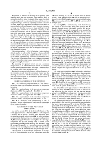
30 years poly-ceramic rotors and water lubricated screw
US6093008
1. US006093008A
Ulllted States Patent [19] [11] Patent Number: 6,093,008
Kirsten [45] Date of Patent: Jul. 25, 2000
[54] WORM-DRIVE COMPRESSOR 609405 2/1935 Germany .
1954738 7/1966 Germany .
[76] Inventor: Guenter Kirsten, Erzbergerstrasse 13, 1428125 11/1968 Germany -
D-08451 Crimmitschau, Germany 84891 10/1971 Germany -
2520667 11/1976 Germany .
[21] Appl. No.: 08/973,167 2621303 11/1976 Germany .
3031801 3/1981 Germany .
[22] PCT Filed: May 18, 1996 3813272 11/1988 Germany .
_ 4227332 2/1993 Germany .
[86] PCT No.. PCT/EP96/02078 germany _
. ermany .
§ 371 Date‘ NOV‘ 19’ 1997 397937 3/1960 Switzerland .
§ 102(6) Date; Nov_ 19, 1997 342791 2/1931 United Kingdom .
650606 2/1951 United Kingdom .
[87] PCT Pub. No.: W096/37706 2254376 10/1992 United Kingdom ................... 418/200
PCT Pub Date: NOV- 28’ 1996 Primary Examiner—Hoang Nguyen
[30] Foreign Application Priority Data Attorney, Agent, or Fzrm—D1ller, Ramlk & Wight, PC
May 25, 1995 [DE] Germany ........................... 195 19 247 [57] ABSTRACT
[51] Int. Cl.7 ........................................................ F01C 1/16 The invention relates to a Worn-rive compressor (10) With a
[52] US. Cl. ......................................... 418/201.1; 418/200 main rotor Shaft (18) On Which are ?tted at least one ?rst and
[58] Field of Search 418/200 201 1 one second main rotor (14, 16), each of Which meshes With
~~~~~~~~~~~~~~~~~~~~~~~~~~~~~" ’ ' a matching ?rst or second sub-rotor (20, 22) on a rotor
[56] References Cited layshaft (24). To provide a hard-Wearing, economically
produced and highly ef?cient Worm-drive compressor (10),
US. PATENT DOCUMENTS the hearings of the rotor main and layshafts (18, 24) are
4 259 045 3/1981 Teruyama ................................ 418/200 thatched to the Compressed gas Supply th Such a Way that the
418000 loads imposed on the shafts by the pressures produced are
418/200 X absorbed by radially operating bearings (40, 42, 44, 47) near
the point at Which they arise.
5,496,163 3/1996 Griese et a1. .
5,549,463 8/1996 OZaWa .............................. ..
FOREIGN PATENT DOCUMENTS
470400 12/1950 Canada ................................ .. 418/200 24 Claims, 5 Drawing Sheets
7L m-ri /th
2h 76 {12
3h 22
2. U.S. Patent Jul. 25,2000 Sheet 1 0f5 6,093,008
FIGJ
./ O /
FIE
i //"X/ H1 l
- O
O ‘/l 0 I 7t
__// //
1 /
U /
3. U.S. Patent Jul. 25,2000 Sheet 2 0f5 6,093,008
t
4H/.
2aB1IIIlI
2:.WIE.
7. 6,093,008
1
WORM-DRIVE COMPRESSOR
BACKGROUND OF THE INVENTION
The invention relates to a screW-type compressor With a
primary rotor assembly shaft on Which at least a ?rst and a
second primary rotor are arranged, respectively meshing
With a matching ?rst and second secondary rotor on a
secondary rotor assembly shaft.
To compress gaseous matter such as air and to make it
available as compressed gas, screW-type compressors are
used. These screW-type compressors must be adapted to the
operative conditions of the gas to be compressed, it being of
particular importance to provide the gas in a desired amount
and With a desired pressure. Moreover, requirements con
cerning the purity of the gas are often made so that oil
lubrication may sometimes be undesirable.
The amount of compressed gas and the gas pressure
obtainable With the screW-type compressor depend on the
rotor geometry of the rotors used in the screW-type com
pressor and the rotational speed of the rotors. HoWever, it
has been found that due to the peripheral velocities occur
ring at the rotor circumference and due to sealing problems
betWeen the rotors of a screW-type compressor stage, the
possibilities of increasing the rotational speed and the rotor
diameter are limited.
To avoid restrictions in the amount of compressed gas
delivered by the screW-type compressor, one has developed
screW-type compressors With double-helical gearing having
tWo rotors on the primary rotor assembly shaft and the
secondary rotor assembly shaft, respectively, With Which the
amount of compressed gas delivered by the screW-type
compressor could be increased.
Such a double-screW compressor is knoWn from DE 30 31
801 A1. This screW-type compressor has primary rotors With
leftWard and rightWard helical screWs, arranged on a com
mon shaft adjoining each other at the end faces in a joining
plane and meshing With corresponding leftWard and right
Ward helical secondary rotors also arranged on a common
shaft and adjoining each other at the end faces. In this
screW-type compressor, the gaseous medium to be com
pressed is transported to the center of the screW-type
compressor, from Where it is let out in the radial direction.
To avoid the effect knoWn as the “enclosed pocket” and to
guarantee a good transport of the compressed gas, the tWo
rotor pairs are angularly offset With respect to each other so
that the enclosed pocket of the one rotor pair that is forming
may be vented into the still open helical groove of the
trailing opposite rotor pair. Since the rotor pairs abut at their
centers, the primary and secondary rotor assembly shafts are
each supported at their opposite outer ends.
HoWever, due to the over?oW of the compressed gas, the
knoWn screW-type compressor has an unsatisfactory effi
ciency. Moreover, the supporting of the primary and sec
ondary rotor assembly shafts is expensive, since the forces
occurring at the rotors cause a complex load characteristic of
the primary and secondary assembly rotor shaft, both in the
radial and the axial directions, resulting in high Wear.
SUMMARY OF THE INVENTION
It is the object of the present invention to provide a
long-Wearing screW-type compressor that may be produced
With little effort and has a high efficiency.
The object is solved, according to the invention, With the
features of each of claims 1, 4 and 13.
According to the invention, the Wear of the screW-type
compressor is reduced by adapting the bearing of the pri
10
15
20
25
30
35
40
45
55
60
65
2
mary and secondary rotor assembly shafts such to the Way
of the compressed gas transport that the loads on the shafts,
caused by the pressures occurring, are accommodated by
radially acting bearings near their place of origin. By this
manner of bearing, stricter tolerances may be selected so that
a higher efficiency can be obtained. The present manner of
bearing further is advantageous in that the effort for the
bearing is reduced, Whereby the screW-type compressor can
be made at loWer cost.
The number of rotors per shaft is not limited. Basically,
three and more rotors could be provided. HoWever, if tWo
rotors are provided, they are preferably spaced axially from
each other. The axial distance betWeen the rotors makes it
possible to support both the primary rotor assembly shaft
and the secondary rotor assembly shaft in the area betWeen
the primary rotors and the secondary rotors so that, When
carrying off the compressed gas in the area betWeen the
rotors, the forces generated can also be taken up in this area.
When the compressed gas is carried off at the outer front end
faces of the rotor pairs and thus the greatest forces occur
there, the bearing is suitably provided at the outer front faces
of the rotor pairs.
According to a preferred embodiment of the invention,
the rotor geometries of the primary rotors are adapted to
each other such that the forces of the compressed gas of the
tWo primary rotors acting in the axial direction cancel each
other at least partly, preferably completely. The compensa
tion of the compressed gas forces acting in the axial
direction, Which results from the surfaces active in the axial
direction and from the pressure on the respective surface,
has the effect that the Wear on the primary rotor assembly
shaft and the bearing effort for the same are reduced.
By a mirror symmetric design of the tWo primary rotors,
it is achieved that the structural effort in designing rotors is
reduced. An arrangement of tWo mirror symmetric primary
rotors Without mutual angular offset and exactly in phase on
the primary rotor assembly shaft guarantees that also the
course of the pressure in time that changes With every neW
angular position of the rotors, has no outWard effect on the
axial forces transmitted by the primary rotor assembly shaft
so that bearings acting in the axial direction can be omitted.
Preferably, the tWo secondary rotors and the second
primary rotor are supported at one side only. Such cantile
vered bearing is advantageous in that a change in the ratio
D/L (diameter/rotor length) can readily be made and in that
the construction of novel screW-type compressors With
altered L/D ratio, and thus an altered absorption volume,
does not require the design of novel rotor geometries, since
the cantilevered rotors may readily be shortened. If,
hoWever, the secondary rotors and the second primary rotor
each have their outer end faces provided With a bearing
opening for receiving bearing bushings, greater forces can
be accommodated by additional simple and loW cost bear
ings at the end faces so that the screW-type compressor can
be operated at higher pressures.
By virtue of an adjustment device arranged in the sec
ondary rotor assembly shaft for adjusting the axial distance
of the tWo secondary rotors, the secondary rotors can be
made independent from each other and from the primary
rotors, the play betWeen the primary rotor assembly shafts
and the respective secondary rotor being adjustable poste
riorly by means of the adjusting device. This structure not
only reduces the production effort, but it also minimiZes the
return bloW losses occurring during the operation of the
screW-type compressor, since smaller tolerances can be
used.
8. 6,093,008
3
Regardless of Whether the bearing of the primary rotor
assembly shaft and the secondary rotor assembly shaft is
realized centrally or at the front ends of the respective shaft,
it is advantageous to provide a partitioning Wall betWeen tWo
compressor stages formed by a primary rotor and a second
ary rotor, respectively. By means of this partitioning Wall, an
uncontrolled over?oW of pressure gases from one compres
sor stage into the other compressor stage can be prevented.
Preventing the over?oW is of particular advantage, if the
screW-type compressor is to be operated in a kind of tandem
operation, Wherein the pressure medium to be compressed
?rst ?oWs through the ?rst and then through the second
compressor stage. In this design, it is advantageous to use
Water injection for cooling in the ?rst compressor stage. In
the second compressor stage, Water injection is not neces
sary. In one embodiment of the screW-type compressor With
successively ?oWn-through compressor stages, it is advan
tageous to provide different rotor geometries for the ?rst and
the second compressor stages that are adapted to the respec
tive changes in volume.
The rotors may have a 5/7 or 6/7 gearing. Larger numbers
of teeth lead to an unfavorable absorption volume, and With
smaller numbers of teeth, the height of the teeth becomes to
great and the corresponding rotor shaft becomes too thin.
The preferred 5/7 gearing of the rotors causes a compressed
gas ?oW that pulses only Weakly, generates little noise and
has good strength properties.
By providing tWo primary rotors cast on a common
integral shaft, it is achieved that the rotors are arranged
Without a mutual angular offset, Which has a positive effect
on avoiding aXial forces acting outWard.
Further advantageous embodiments and developments of
the invention result from the dependent claims and the
draWings in connection With the speci?cation. The folloWing
is a detailed description of the invention With reference to
tWo embodiments thereof.
BRIEF DESCRIPTION OF THE DRAWINGS
FIG. 1 is a simpli?ed perspective vieW of a ?rst embodi
ment of a screW-type compressor according to the present
invention,
FIG. 2 is a sectional vieW of the screW-type compressor
illustrated in FIG. 1 along line II—II in FIG. 1,
FIG. 3 is a sectional vieW of the screW-type compressor
illustrated in FIG. 1 along line III—III in FIG. 1,
FIG. 4 is a sectional vieW of the screW-type compressor
illustrated in FIG. 1 along line IV—IV in FIG. 1, and
FIG. 5 is a sectional vieW corresponding to FIG. 2,
shoWing a second embodiment of a screW-type compressor
of the present invention.
DESCRIPTION OF THE PREFERRED
EMBODIMENT
As can be seen in FIG. 2, the ?rst embodiment of the
screW-type compressor I 0 shoWn in FIGS. 1 to 4 comprises
a housing 12 in Which a primary rotor assembly shaft
carrying tWo ceramic primary rotors 14, 16 and a secondary
rotor assembly shaft carrying tWo ceramic secondary rotors
20, 22 are arranged. Within the housing 12 of the screW-type
compressor 10, the ?rst primary rotor 14 forms a ?rst
compressor stage 26 together With the ?rst secondary rotor
22 arranged in parallel to a second compressor stage 28
formed by the second primary rotor 16 and the second
secondary rotor 20, With respect to the pressure gas ?oW.
The operation of the screW-type compressor 10 is in?u
enced by the arrangement of the tWo compressor stages 26,
10
15
20
25
30
45
55
60
65
4
28 in the housing 12, as Well as by the kind of bearing
primary rotor assembly shaft 18 and the secondary rotor
assembly shaft 24, it being important to note that the housing
12 accommodating all rotors 14, 16, 20, 22 is composed of
multiple parts.
The housing 12 has a central bearing block divided along
the planes of the rotor aXes With jacket portions 32, 34
laterally ?anged thereto. The jacket portions 32, 34, the
length of Which respectively corresponds to the length of an
associated rotor pair 14, 40, 16, 22 of the ?rst or second
compressor stage 26, 28, and Which enclose the rotors of the
?rst compressor stage 26 and the second compressor stage
28, have their outer end faces closed by a ?rst and second
end cover 36, 38, respectively. In the center of the screW
type compressor 10, the tWo compressor stages 26, 28 are
separated from each other by the bearing block 30 acting as
a partitioning Wall. So-called cover ?aps are formed at the
jacket portions 32, 34 that are disposed on the intake side of
the rotors 14, 16, 20, 22 and serve to return coolant and
lubricant throWn off by the rotors 14, 16, 20, 22.
To support the primary rotor assembly shaft and the
secondary rotor assembly shaft 18, 24, the bearing block 30
has tWo split bearings 40, 42, 44, 46 for each shaft, the loWer
bearing shells 48a to 48d thereof being arranged in a loWer
portion 50 of the bearing block, Whereas the upper bearing
shells 52a to 52d are arranged in an upper portion 54 of the
bearing block 30. The bearing shells 48a to 48d, 52a to 52d
that are provided With lubricant bores (not illustrated)for oil
or Water lubrication and are arranged directly adjoining the
rotors, comprise the respective shaft so as to take up radial
forces.
The screW-type compressor 10 is driven by a drive shaft
56 integrally formed With the primary rotor assembly shaft
18, the drive shaft projecting through the second end cover
38 at one of the end faces of the screW-type compressor 10
and being supported With respect to the end cover 38 in a
needle bearing 58. In order to seal the second compressor
stage 28, closed by the second end cover 38, toWards the
outside, a sealing arrangement 60 is provided that seals the
drive shaft 56 against the housing 12.
The drive of the screW-type compressor 10 is effected by
rotating the drive shaft 56 counterclockWise as indicated by
the arroW A. By this rotation, the ?rst and the second
primary rotor 14, 16 cast on the primary rotor assembly shaft
18 are driven. The secondary rotors 20, 22 are driven
indirectly, meshing With the primary rotors 14, 16 that are
driven by the primary rotor assembly shaft 16.
The conduction of the gas to be compressed may best be
seen in FIG. 3. The gas to be compressed is ?rst supplied to
the screW-type compressor 10 at the top 62 of the upper
portion 54 of the bearing block. This may be done either
directly or indirectly through intake ?lters and intake cool
ers. From the inlet opening 64 at the top 62 of the upper
bearing block portion 54, the gas is ?rst conducted to the tWo
end faces of the screWtype compressor 10. From the end
faces of the screW-type compressor 10, the compressed gas
spreads above the primary rotors and the secondary rotors
14, 16, 20, 22 forming the ?rst and second compressor
stages 26, 28. By rotating the rotors 14, 16, 20, 22 and by the
meshing of the same resulting from the rotation of the rotors
14, 16, 20, 22, the air is compressed and conveyed to
controlling edges 66, 68 at the loWer bearing block portion
50, from Where the compressed air is conducted out in the
aXial direction of the respective compressor stage 14, 16 and
to a pressure relief opening 72 at the bottom 70 of the loWer
bearing block portion 50.
9. 6,093,008
5
It is evident from FIG. 3 that at the respective upper side
of the primary rotors and secondary rotors 14, 16 always
only the inlet pressure (P1) prevails. HoWever, there alWays
is a higher pressure (PmaX) at the opposite side so that the
primary rotor assembly shaft and the secondary rotor assem
bly shaft 18, 24 are subjected to a circulating bending load.
What is more, this bending load is pulsed since the perma
nent opening and closing of compression chambers create
pressure pulses.
To keep the pressure pulsation loW, the primary rotors 14,
16 each have ?ve teeth meshing With seven teeth of the
secondary rotors 20, 22. To avoid outWard acting aXial
forces, one of the tWo primary rotors 14 has a rightWard
heliX, Whereas the other primary rotor 16 has a leftWard
heliX. The tWo primary rotors 14, 16 are arranged on the
primary rotor assembly shaft 18 Without mutual angular
offset. Since both primary rotor assembly shafts 14, 16
further have equal lengths, the compressed gas forces acting
on the teeth of the primary rotor assembly shaft 14, 16 cancel
each other out so that the bearing of the primary rotor
assembly shaft 18 does not require an aXial guiding.
The screW-type compressor 10 is produced by ?rst casting
the tWo primary rotors 14, 16 on a prepared primary rotor
assembly shaft 18. Similarly, the secondary rotors 20, 22 are
cast around a prepared secondary rotor assembly shaft 24.
Both shafts 18, 24 are then placed into their respective loWer
bearing shells 48a to 49d. Thereafter, the bearing block 30
is closed by placing the ?nished upper bearing block portion
54 With the bearing shells 52a to 52d arranged therein onto
the loWer bearing block portion 50. The centering during this
positioning is done as in the ?nishing of the upper bearing
block portion 54 and the loWer bearing block portion using
centering sleeves Which, for centering the upper bearing
block portion 54 and the loWer bearing block portion 50, are
provided surrounding tensioning screW means 76. The
divided structure of the bearing block 30 thereby substan
tially facilitates the ?ne machining and the ?nishing of the
individual components, as Well as the assembly of the
screW-type compressor 10.
The second embodiment of the screW-type compressor
110 illustrated in FIG. 5 differs from the ?rst embodiment of
the screW-type compressor 10 only in a feW details. Ele
ments corresponding to elements of the ?rst embodiment are
therefore designated by a reference numeral incremented by
100 With regard to the corresponding reference numeral in
the FIGS. 1 to 4. For the description of these elements,
reference should be made to the description of the ?rst
embodiment.
As in the ?rst embodiment, the primary rotors 114, 116
and the secondary rotors 120, 122 of the second embodiment
are ?rmly connected With a primary rotor assembly shaft 118
and a secondary rotor assembly shaft 124. HoWever, other
than in the ?rst embodiment, the secondary rotor assembly
shaft 124 has an adjusting device 180 for adjusting the aXial
distance betWeen the secondary rotors 120, 122. The adjust
ing device 180 is designed such Within the secondary rotor
assembly shaft 124 that a conical projection 182 of a ?rst
secondary rotor assembly subshaft 184 eXtends into a coni
cal recess 186 of a second secondary rotor assembly sub
shaft 188. The tWo independent secondary rotor assembly
subshafts 184, 188 are connected by means of a tensioning
screW 190 extending in the aXial direction of the secondary
rotor assembly subshafts and together form the secondary
rotor assembly shaft 124.
In order to adjust the distance betWeen the tWo secondary
rotors 120, 122 such that they mesh With their respective
10
15
20
25
35
40
45
55
60
65
6
primary rotor 114, 116 With as little Wear as possible, The
tWo secondary rotor assembly subshafts 184, 188 are
assembled to one another. Subsequently, the distance of the
tWo secondary rotors 120, 122 is adjusted by manipulating
the tensioning screW 190. By ?nishing the front end faces of
the secondary rotors 120, 122, the secondary rotors are
adapted to the housing 12.
As an alternative to the adjusting device 180 illustrated,
one may also provide an adjusting means, Wherein the tWo
secondary rotor assembly subshafts have superposed cylin
drical sections. The distance betWeen the secondary rotors
can then be adjusted by means of a tensioning screW and
interposed disk springs.
Different from the ?rst embodiment of the screW-type
compressor 10, the second embodiment of the screW-type
compressor 110 further has additional shaft bearings 192a to
192C arranged at the front ends of the secondary rotors 120,
122 facing toWards the end covers 136, 138 and at a front
end of the primary rotor 114 facing toWards the end cover
136. The shaft bearings 192a to 1926 each have a circular
cylindrical bearing pin 194a to 194C ?Xed in the respective
end cover 136, 138, the pin engaging into a bearing bushing
196a to 196C rotating together With the respective rotor. The
bearing bushings 196a to 196C are in turn arranged in
bearing openings 198a to 1986 Which are cylindrical
recesses, the bushings being in press ?t and end ?ush With
the respective end face at the front end of the respective
primary rotor and secondary rotor 114, 120, 122. By pro
viding the bearing bushings 196a to 196b in the rotors 114,
120, 122, the structural length of the screW-type compressor
is reduced.
The screW-type compressor 10 of the ?rst embodiment is
adapted to generate pressures up to about 13 bar, despite the
cantilevered bearing of the rotors 14, 20, 22. If, hoWever, the
front ends of the rotors 14, 16, 20, 22; 114, 116, 120, 122
facing toWards the end covers are supported, pressures of up
to 20 bar may be generated even at single-stage operation
and With Water injection. Together With the injection of
Water that counteracts the generation of heat, Water lubri
cation of the bearings is provided independent of the con
crete design of the screW-type compressor. HoWever, Water
and oil lubrication are interchangeable.
Although a preferred embodiment of the invention has
been speci?cally illustrated and described herein, it is to be
understood that minor variations may be made in the appa
ratus Without departing from the spirit and scope of the
invention, as de?ned the appended claims.
I claim:
1. A screW-type compressor comprising a primary rotor
assembly shaft (118) carrying at least a ?rst primary rotor
(114) and a second primary rotor (116), a secondary rotor
assembly shaft (24, 124) carrying at least a ?rst secondary
rotor (120) and a second secondary rotor (122), said ?rst
primary rotor (114) being in substantially meshed relation
ship With said ?rst secondary rotor (120), said second
primary rotor (116) being in substantially meshed relation
ship With said second secondary rotor (122), said primary
rotors (114, 116) being aXially spaced from each other, said
secondary rotors (120, 122) being aXially spaced from each
other, means (130) for supporting the primary rotor assem
bly shaft (118) and the secondary rotor assembly shaft (124)
in an area betWeen the primary rotors (114, 116) and the
secondary rotors (120, 122), and at least one of said primary
rotor assembly shaft (118) and said secondary rotor assem
bly shaft (124) including means (180) for adjusting the aXial
distance of at least one of said primary rotors (114, 116) and
said secondary rotors (120, 122) relative to each other.
10. 6,093,008
7
2. The screW-type compressor as de?ned in claim 1
Wherein said adjusting means (180) adjust the axial distance
of said secondary rotors (120, 122) relative to each other.
3. The screW-type compressor as de?ned in claim 1
Wherein the ?rst primary rotor (114) forms a ?rst compressor
stage (126) With the ?rst secondary rotor (120), the second
primary rotor (116) forms a second compressor stage (128)
With the secondary rotor (122), and a partitioning Wall (130)
is disposed betWeen the tWo compressor stages (126, 128).
4. The screW-type compressor as de?ned in claim 1
Wherein the ?rst primary rotor (114) forms a ?rst compressor
stage (126) With the ?rst secondary rotor (120), the second
primary rotor (116) forms a second compressor stage (128)
With the secondary rotor (122), a partitioning Wall (130) is
disposed betWeen the tWo compressor stages (126, 128), and
means for conducting the pressure medium Which is to be
compressed to the ?rst compressor stage (126) and subse
quently to the second compressor stage (128).
5. The screW-type compressor as de?ned in claim 1
Wherein the ?rst primary rotor (114) forms a ?rst compressor
stage (126) With the ?rst secondary rotor (120), the second
primary rotor (116) forms a second compressor stage (128)
With the secondary rotor (122), a partitioning Wall (130) is
disposed betWeen the tWo compressor stages (126, 128), and
means for conducting the pressure medium Which is to be
compressed through the ?rst and second compressor stages
(126, 128) in tWo substantially parallel ?oW paths.
6. The screW-type compressor as de?ned in claim 1,
Wherein at least one of said primary rotor assembly shaft
(118) and said secondary rotor assembly shaft (124) include
separate relatively axially movable subshafts (184, 188), and
said adjusting means (180) is constructed and arranged to
axially move said subshafts relative to each other to adjust
said axial distance.
7. The screW-type compressor as de?ned in claim 1
Wherein said secondary rotor assembly shaft (124) includes
separate relatively axially movable subshafts (184, 188), and
said adjusting means (180) is constructed and arranged to
axially move said subshafts relative to each other to adjust
said axial distance.
8. The screW-type compressor as de?ned in claim 6
Wherein said adjusting means (180) is a screW.
9. The screW-type compressor as de?ned in claim 6
Wherein said adjusting means (180) is a screW movable in
coaxial relationship to an axis of said subshafts (184, 188).
10. The screW-type compressor as de?ned in claim 6
Wherein said adjusting means (180) is a screW movable in
coaxial relationship to an axis of said subshafts (184, 188),
and said screW is accessible for manipulation through a bore
in one of said rotors.
11. The screW-type compressor as de?ned in claim 1
Wherein said subshafts (184, 188) are de?ned by a conical
projection (182) received in a conical recess (186).
12. The screW-type compressor as de?ned in claim 8
Wherein said subshafts (184, 188) are de?ned by a conical
projection (182) received in a conical recess (186).
10
15
20
25
30
35
40
45
55
8
13. The screW-type compressor as de?ned in claim 9
Wherein said subshafts (184, 188) are de?ned by a conical
projection (182) received in a conical recess (186).
14. The screW-type compressor as de?ned in claim 7
Wherein said adjusting means (180) is a screW.
15. The screW-type compressor as de?ned in claim 7
Wherein said adjusting means (180) is a screW movable in
coaxial relationship to an axis of said subshafts (184, 188).
16. The screW-type compressor as de?ned in claim 7
Wherein said adjusting means (180) is a screW movable in
coaxial relationship to an axis of said subshafts (184, 188),
and said screW is accessible for manipulation through a bore
in one of said rotors.
17. The screW-type compressor of claim 1 characteriZed
in that both secondary rotors (120, 122) and one of the
primary rotors (114) each have an outer end face provided
With a bearing opening (198a—198c) for receiving a bearing
bushing (196a—196c).
18. The screW-type compressor of claim 1, characteriZed
in that a compressed medium is discharged in the axial
direction of the primary rotors and the secondary rotors (114,
116, 120, 122).
19. The screW-type compressor of claim 1 characteriZed
in that the rotor geometries of the primary rotors (114, 116)
are constructed and arranged such that axially directed
pressure gas forces of both primary rotors (114, 116) com
pensate each other at least partly.
20. The screW-type compressor of claim 1 characteriZed
in that the rotor geometries of the primary rotors (114, 116)
are constructed and arranged such that axially directed
pressure gas forces of both primary rotors (114, 116) com
pensate each other completely.
21. The screW-type compressor of claim 1, characteriZed
in that the rotor geometries of the secondary rotors (120,
122) are constructed and arranged such that axially directed
pressure gas forces of both secondary rotors (120, 122)
compensate each other at least partly.
22. The screW-type compressor of claim 1 characteriZed
in that the rotor geometries of the secondary rotors (120,
122) are constructed and arranged such that axially directed
pressure gas forces of both secondary rotors (120, 122)
compensate each other completely.
23. The screW-type compressor of claim 20 characteriZed
in that the primary rotor (114) and the second primary rotor
(116) have mirror symmetric geometries.
24. The screW-type compressor of claim 23, characteriZed
in that the ?rst and second primary rotors (114, 116) are
arranged on the primary rotor assembly shaft (118) Without
mutual angular offset so that in the course of time the
pressure at the ?rst primary rotor (114) is identical With that
at the second primary rotor (116).