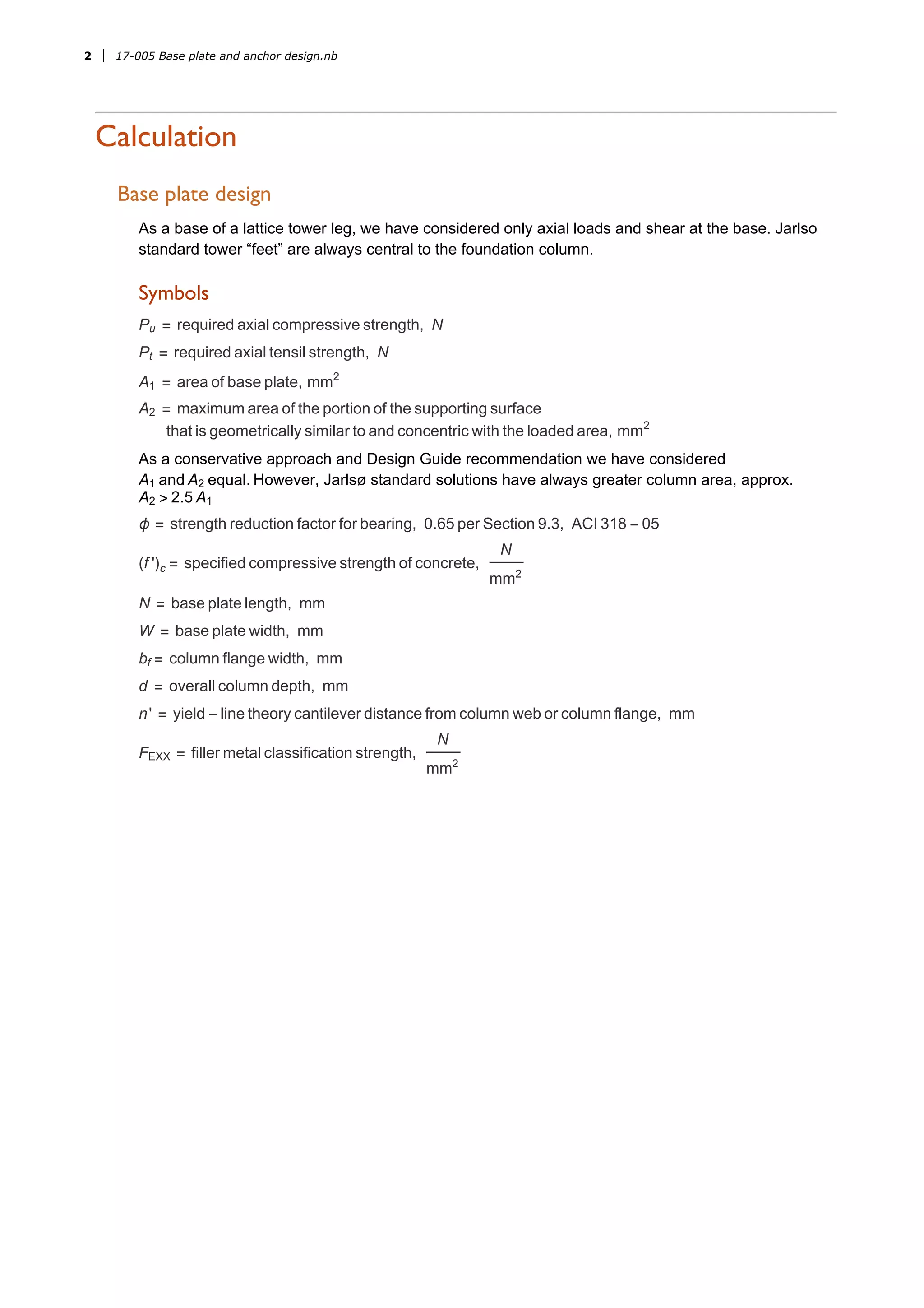
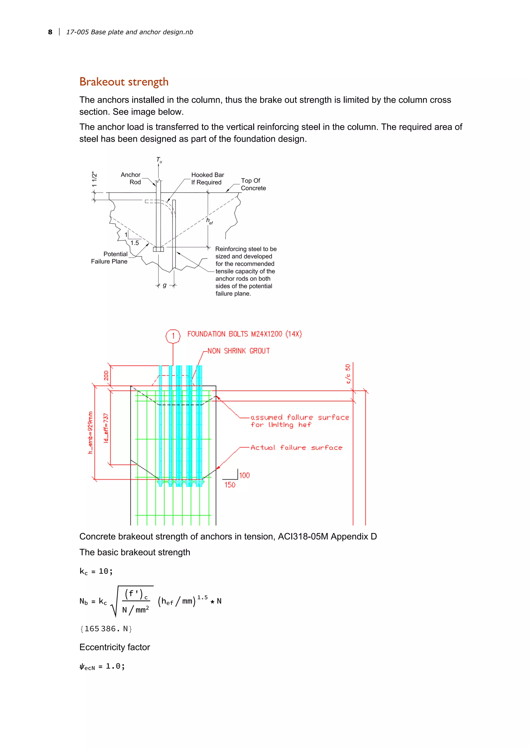
�������������������������������
���������
���������������������������������������
������������������
�����������
�����������������
As a base of a lattice tower leg, we have considered only axial loads and shear at the base. Jarlso
standard tower “feet” are always central to the foundation column.
�������
Pu = required axial compressive strength, N
Pt = required axial tensil strength, N
A1 = area of base plate, mm2
A2 = maximum area of the portion of the supporting surface
that is geometrically similar to and concentric with the loaded area, mm2
As a conservative approach and Design Guide recommendation we have considered
A1 and A2 equal. However, Jarlsø standard solutions have always greater column area, approx.
A2 > 2.5 A1
ϕ = strength reduction factor for bearing, 0.65 per Section 9.3, ACI 318 - 05
(f ')c = specified compressive strength of concrete,
N
mm2
N = base plate length, mm
W = base plate width, mm
bf = column flange width, mm
d = overall column depth, mm
n' = yield - line theory cantilever distance from column web or column flange, mm
FEXX = filler metal classification strength,
N
mm2
2��� 17-005 Base plate and anchor design.nb
<< Units`
�����������������������
Towers under check:
myTowers = {"RTB15m"};
Material properties
Pu = {333 000} N;
Pt = {315 000} N;
f'c
= 25 N  mm^2;
fy = 345 N  mm^2;
fyre = 420 N  mm^2;
FEXX = 345 N  mm^2;
ϕ = 0.65;
The minimum base plate area can be determined by the following equation
A1 (req) =
Pu
ϕ * 0.85 * f'c
24 108.6 mm2

Optimize the base plate dimensions, N and B
N ≈ A1 (req) + Δ , where Δ =
0.95 d - 0.8 bf
2
, then B =
A1 (req)
N
17-005 Base plate and anchor design.nb ���3
bf = {100} mm;
d = bf;
Δ = N0.95 * d - 0.8 * bf  2
{7.5 mm}
Wreq = Simplify A1 (req) , mm > 0 + Δ
{162.769 mm}
Since all the tower legs are equal angles the length shall be equal to width
Nreq = Wreq;
Check the tower base plate
4��� 17-005 Base plate and anchor design.nb
Wprov = {400} mm;
Wreq  Wprov /. x_ /; x < 1 → "PASS"
{PASS}
Nprov = Wprov;
17-005 Base plate and anchor design.nb ���5
�������������������������������������������
mprov =
Nprov - 0.95 * d
2
{152.5 mm}
nprov =
Wprov - 0.85 * bf
2
{157.5 mm}
A1 = Wprov ^2
160 000 mm2

Pp = 0.85 * f'c
* A1
3.4 × 10⁶
N
X =
4 d * bf
d + bf^2
Pu
ϕ * Pp
{0.150679}
λ =
2 X
1 + 1 - X
/. x_ /; x > 1 → 1
{0.404014}
λn' = λ
Simplify d * bf , mm > 0
4
{10.1003 mm}
Find the lmax
lmax = Max /@ Transpose{mprov, nprov, λn'}  mm mm
{157.5 mm}
Determine minimum thickness of the base plate
tmin = lmax
2 Pu
ϕ * fy * Nprov * Wprov
{21.4581 mm}
tprov = {30} mm;
thCheck = tmin / tprov /. x_ /; x <= 1 -> "PASS"
{PASS}
6��� 17-005 Base plate and anchor design.nb
������������
�������
Check the welding of the column to the base plate.
Since there are anchor bolts outside the flanges of the angle, the forces can be assumed to be
distributed onto the both full legs of the angle. Conservatively the thickness and radius of the angle
will not be applied.
Fillet weld will be applied to both sides of the main leg + to the stiffeners as lengthen the legs of the
angle and 2 perpendicular (see drawing above) as min. 100mm in length.
Maximum welding load:
beff = bf * 2 + 2 * bf - 16 mm - 6 mm + 100 mm * 2 * 2 + 100 mm * 2 * 2
{1156 mm}
maxload = N
Pt
beff


272.491 N
mm

Minimum size of fillet welds according to AISC specification Table J2.4
weld = 6 mm;
Nominal weld strength per mm for the fillet weld
Rn = Fnw weld
1611.25 N
mm
Where
Fnw = 0.6 * FEXX * 1.0 + 0.5 * SinPi  4
1.5

268.541 N
mm2
weldCheck = maxload  Rn /. x_ /; x < 1 -> "PASS"
{PASS}
17-005 Base plate and anchor design.nb ���7
�����������������
The anchors installed in the column, thus the brake out strength is limited by the column cross
section. See image below.
The anchor load is transferred to the vertical reinforcing steel in the column. The required area of
steel has been designed as part of the foundation design.
Concrete brakeout strength of anchors in tension, ACI318-05M Appendix D
The basic brakeout strength
kc = 10;
Nb = kc
f'c
N  mm2
hef  mm
1.5
* N
{165 386. N}
Eccentricity factor
ψecN = 1.0;
8��� 17-005 Base plate and anchor design.nb
Modification factor for edge effects in tension
;
ca,min = {266} mm;
Since the anchors are located less than 1.5 hef from three or more edges, the value of hef as per
below
smax = {142} mm;
ca,max = {333} mm;
hef = Max /@ Transposeca,max / 1.5, ca,min
1
3
  mm mm
{222. mm}
Concrete brakeout cone area for group
ANc = {600 mm}^2
360 000 mm2

Concrete brakeout cone area for a single anchor
ANco = 9 * hef ^2
443 556. mm2

feDn[x_] := IfThreadca,min / mm < 1.5 hef  mm, 0.7 + 0.3
ca,min
1.5 hef
, 1
ψedN = feDn /@ 0.7 + 0.3
ca,min
1.5 hef
{0.93964}
Cracking factor, assumed that the region of analysis where the anchors are placed is cracked
ψcN = 1.0;
Modification factor for post-installed anchors.
17-005 Base plate and anchor design.nb ���9
ψcpN = 1.0;
ϕNcbg = ϕ
ANc
ANco
ψecN ψedN ψcN ψcpN Nb
{81 983.8 N}
brkOutCheck = ThreadϕNcbg  N > Pt  N
{False}
Thus, it is necessary to transfer the anchor load to the vertical reinforcing steel in the column.
Required area of steel:
Areq =
Pt
0.9 * fyre
833.333 mm2

ACI 318 (12.2.3)
ψe = 1.0;
ψt = 1.0;
ψs = 1.0;
λ = 1.0;
nre = {12};
dre1 = {12} mm;
Below the necessary development length for the rebars without hooks. Necessary vertical length
ld cumputed as below
ld =
fyre
1.1 f'c
ψt ψe ψs λ
2.5 N
mm2
dre1
{366.545 mm}
Where
Thread
cb + Ktr * (mm)
dre1
> 2.5
{True}
Ktr =
Atr * fyre
10 * s * n
mm  N
{51.7439}
Atr = Ndre1 ^2 * Pi  4 * 5
565.487 mm2

dre2 = 10 mm;
10��� 17-005 Base plate and anchor design.nb
cb = 50 mm;
s = 153 mm;
Number of bars being developed along the plane of splitting:
n = 3;
The column reinforcement are located at the edge of the column (see drawing above). Using a
Class B splice factor with 1.3 the necessary minimum development length le as below:
le =
Pt * 1.3 * ld
nre * dre1 ^2 * Pi  4 * 0.9 * fyre
{292.588 mm}
Anchor bolt length:
lanch = 750 mm;
ldeff = lanch  mm - 200 - 50 - 65 mm -
ca,max - 50 mm
1.5
{246.333 mm}
devLengthCheck = Threadldeff  mm > le  mm /. x_ /; x ⩵ True -> "PASS"
False
The necessary, ledevelopment length is provided.
17-005 Base plate and anchor design.nb ���11
�������
The following are the summarized results for all the checks above
num = 1;
thCheckFormatted = Table[If[StringMatchQ[thCheck[[i]], "PASS"],
Style[thCheck[[i]], Green], Style[thCheck[[i]], Red]], {i, 1, num}]
{PASS}
weldCheckFormatted = Table[If[StringMatchQ[weldCheck[[i]], "PASS"],
Style[weldCheck[[i]], Green], Style[weldCheck[[i]], Red]], {i, 1, num}]
{PASS}
brkOutCheckFormatted =
Table[If[TrueQ[brkOutCheck[[i]]], Style[brkOutCheck[[i]], Green],
Style[brkOutCheck[[i]], Gray, Italic]], {i, 1, num}]
{False}
devLengthCheckFormatted =
Table[If[StringMatchQ[devLengthCheck[[i]], "PASS"], Style[
devLengthCheck[[i]], Green], Style[devLengthCheck[[i]], Red]], {i, 1, num}]
������������� ������ �� ���� �� ������� �������� �� �������� � �� ������������[������ ����]�
{If[StringMatchQ[False, PASS],
Style[devLengthCheck〚i〛, Green], Style[devLengthCheck〚i〛, Red]]}
sum = TableForm[
{bf, Pu, Pt, Wprov, tprov, ca,min, ca,max, smax, ANc, nre, dre1, thCheckFormatted,
weldCheckFormatted, brkOutCheckFormatted, devLengthCheckFormatted},
TableHeadings → {{"Main leg size", "Compression",
"Tension", "Base plate size", "Base plate thickness",
"anchor min. edge distance", "anchor max. edge distance",
"max. anchor distance", "Column size", "No. of vertical rebars",
"Diameter of reinforcement", "Thickness check", "Welding check",
"Brakeout cone check", "Developement length check"}, myTowers}]
12��� 17-005 Base plate and anchor design.nb
RTB15m
Main leg size 100 mm
Compression 333 000 N
Tension 315 000 N
Base plate size 400 mm
Base plate thickness 30 mm
anchor min. edge distance 266 mm
anchor max. edge distance 333 mm
max. anchor distance 142 mm
Column size 360 000 mm2
No. of vertical rebars 12
Diameter of reinforcement 12 mm
Thickness check PASS
Welding check PASS
Brakeout cone check False
Developement length check If[StringMatchQ[False, PASS], Style[devLengthCheck〚i〛
17-005 Base plate and anchor design.nb ���13
��������������������
ACI 318 M -
05 Building Code Requirements For Structural Concrete And Commentary
(1)
AISC Steel Design Guide - Base Plate and Anchor Rod Design. Second Edition. (2)
ANSI / AISC 360 - 10 - Specification for Structural Steel Buildings (3)
14��� 17-005 Base plate and anchor design.nb

Base plate and anchor design

  • 1.
  • 2.
    ����������� ����������������� As a baseof a lattice tower leg, we have considered only axial loads and shear at the base. Jarlso standard tower “feet” are always central to the foundation column. ������� Pu = required axial compressive strength, N Pt = required axial tensil strength, N A1 = area of base plate, mm2 A2 = maximum area of the portion of the supporting surface that is geometrically similar to and concentric with the loaded area, mm2 As a conservative approach and Design Guide recommendation we have considered A1 and A2 equal. However, Jarlsø standard solutions have always greater column area, approx. A2 > 2.5 A1 ϕ = strength reduction factor for bearing, 0.65 per Section 9.3, ACI 318 - 05 (f ')c = specified compressive strength of concrete, N mm2 N = base plate length, mm W = base plate width, mm bf = column flange width, mm d = overall column depth, mm n' = yield - line theory cantilever distance from column web or column flange, mm FEXX = filler metal classification strength, N mm2 2��� 17-005 Base plate and anchor design.nb
  • 3.
    << Units` ����������������������� Towers undercheck: myTowers = {"RTB15m"}; Material properties Pu = {333 000} N; Pt = {315 000} N; f'c = 25 N  mm^2; fy = 345 N  mm^2; fyre = 420 N  mm^2; FEXX = 345 N  mm^2; ϕ = 0.65; The minimum base plate area can be determined by the following equation A1 (req) = Pu ϕ * 0.85 * f'c 24 108.6 mm2  Optimize the base plate dimensions, N and B N ≈ A1 (req) + Δ , where Δ = 0.95 d - 0.8 bf 2 , then B = A1 (req) N 17-005 Base plate and anchor design.nb ���3
  • 4.
    bf = {100}mm; d = bf; Δ = N0.95 * d - 0.8 * bf  2 {7.5 mm} Wreq = Simplify A1 (req) , mm > 0 + Δ {162.769 mm} Since all the tower legs are equal angles the length shall be equal to width Nreq = Wreq; Check the tower base plate 4��� 17-005 Base plate and anchor design.nb
  • 5.
    Wprov = {400}mm; Wreq  Wprov /. x_ /; x < 1 → "PASS" {PASS} Nprov = Wprov; 17-005 Base plate and anchor design.nb ���5
  • 6.
    ������������������������������������������� mprov = Nprov -0.95 * d 2 {152.5 mm} nprov = Wprov - 0.85 * bf 2 {157.5 mm} A1 = Wprov ^2 160 000 mm2  Pp = 0.85 * f'c * A1 3.4 × 10⁶ N X = 4 d * bf d + bf^2 Pu ϕ * Pp {0.150679} λ = 2 X 1 + 1 - X /. x_ /; x > 1 → 1 {0.404014} λn' = λ Simplify d * bf , mm > 0 4 {10.1003 mm} Find the lmax lmax = Max /@ Transpose{mprov, nprov, λn'}  mm mm {157.5 mm} Determine minimum thickness of the base plate tmin = lmax 2 Pu ϕ * fy * Nprov * Wprov {21.4581 mm} tprov = {30} mm; thCheck = tmin / tprov /. x_ /; x <= 1 -> "PASS" {PASS} 6��� 17-005 Base plate and anchor design.nb
  • 7.
    ������������ ������� Check the weldingof the column to the base plate. Since there are anchor bolts outside the flanges of the angle, the forces can be assumed to be distributed onto the both full legs of the angle. Conservatively the thickness and radius of the angle will not be applied. Fillet weld will be applied to both sides of the main leg + to the stiffeners as lengthen the legs of the angle and 2 perpendicular (see drawing above) as min. 100mm in length. Maximum welding load: beff = bf * 2 + 2 * bf - 16 mm - 6 mm + 100 mm * 2 * 2 + 100 mm * 2 * 2 {1156 mm} maxload = N Pt beff   272.491 N mm  Minimum size of fillet welds according to AISC specification Table J2.4 weld = 6 mm; Nominal weld strength per mm for the fillet weld Rn = Fnw weld 1611.25 N mm Where Fnw = 0.6 * FEXX * 1.0 + 0.5 * SinPi  4 1.5  268.541 N mm2 weldCheck = maxload  Rn /. x_ /; x < 1 -> "PASS" {PASS} 17-005 Base plate and anchor design.nb ���7
  • 8.
    ����������������� The anchors installedin the column, thus the brake out strength is limited by the column cross section. See image below. The anchor load is transferred to the vertical reinforcing steel in the column. The required area of steel has been designed as part of the foundation design. Concrete brakeout strength of anchors in tension, ACI318-05M Appendix D The basic brakeout strength kc = 10; Nb = kc f'c N  mm2 hef  mm 1.5 * N {165 386. N} Eccentricity factor ψecN = 1.0; 8��� 17-005 Base plate and anchor design.nb
  • 9.
    Modification factor foredge effects in tension ; ca,min = {266} mm; Since the anchors are located less than 1.5 hef from three or more edges, the value of hef as per below smax = {142} mm; ca,max = {333} mm; hef = Max /@ Transposeca,max / 1.5, ca,min 1 3   mm mm {222. mm} Concrete brakeout cone area for group ANc = {600 mm}^2 360 000 mm2  Concrete brakeout cone area for a single anchor ANco = 9 * hef ^2 443 556. mm2  feDn[x_] := IfThreadca,min / mm < 1.5 hef  mm, 0.7 + 0.3 ca,min 1.5 hef , 1 ψedN = feDn /@ 0.7 + 0.3 ca,min 1.5 hef {0.93964} Cracking factor, assumed that the region of analysis where the anchors are placed is cracked ψcN = 1.0; Modification factor for post-installed anchors. 17-005 Base plate and anchor design.nb ���9
  • 10.
    ψcpN = 1.0; ϕNcbg= ϕ ANc ANco ψecN ψedN ψcN ψcpN Nb {81 983.8 N} brkOutCheck = ThreadϕNcbg  N > Pt  N {False} Thus, it is necessary to transfer the anchor load to the vertical reinforcing steel in the column. Required area of steel: Areq = Pt 0.9 * fyre 833.333 mm2  ACI 318 (12.2.3) ψe = 1.0; ψt = 1.0; ψs = 1.0; λ = 1.0; nre = {12}; dre1 = {12} mm; Below the necessary development length for the rebars without hooks. Necessary vertical length ld cumputed as below ld = fyre 1.1 f'c ψt ψe ψs λ 2.5 N mm2 dre1 {366.545 mm} Where Thread cb + Ktr * (mm) dre1 > 2.5 {True} Ktr = Atr * fyre 10 * s * n mm  N {51.7439} Atr = Ndre1 ^2 * Pi  4 * 5 565.487 mm2  dre2 = 10 mm; 10��� 17-005 Base plate and anchor design.nb
  • 11.
    cb = 50mm; s = 153 mm; Number of bars being developed along the plane of splitting: n = 3; The column reinforcement are located at the edge of the column (see drawing above). Using a Class B splice factor with 1.3 the necessary minimum development length le as below: le = Pt * 1.3 * ld nre * dre1 ^2 * Pi  4 * 0.9 * fyre {292.588 mm} Anchor bolt length: lanch = 750 mm; ldeff = lanch  mm - 200 - 50 - 65 mm - ca,max - 50 mm 1.5 {246.333 mm} devLengthCheck = Threadldeff  mm > le  mm /. x_ /; x ⩵ True -> "PASS" False The necessary, ledevelopment length is provided. 17-005 Base plate and anchor design.nb ���11
  • 12.
    ������� The following arethe summarized results for all the checks above num = 1; thCheckFormatted = Table[If[StringMatchQ[thCheck[[i]], "PASS"], Style[thCheck[[i]], Green], Style[thCheck[[i]], Red]], {i, 1, num}] {PASS} weldCheckFormatted = Table[If[StringMatchQ[weldCheck[[i]], "PASS"], Style[weldCheck[[i]], Green], Style[weldCheck[[i]], Red]], {i, 1, num}] {PASS} brkOutCheckFormatted = Table[If[TrueQ[brkOutCheck[[i]]], Style[brkOutCheck[[i]], Green], Style[brkOutCheck[[i]], Gray, Italic]], {i, 1, num}] {False} devLengthCheckFormatted = Table[If[StringMatchQ[devLengthCheck[[i]], "PASS"], Style[ devLengthCheck[[i]], Green], Style[devLengthCheck[[i]], Red]], {i, 1, num}] ������������� ������ �� ���� �� ������� �������� �� �������� � �� ������������[������ ����]� {If[StringMatchQ[False, PASS], Style[devLengthCheck〚i〛, Green], Style[devLengthCheck〚i〛, Red]]} sum = TableForm[ {bf, Pu, Pt, Wprov, tprov, ca,min, ca,max, smax, ANc, nre, dre1, thCheckFormatted, weldCheckFormatted, brkOutCheckFormatted, devLengthCheckFormatted}, TableHeadings → {{"Main leg size", "Compression", "Tension", "Base plate size", "Base plate thickness", "anchor min. edge distance", "anchor max. edge distance", "max. anchor distance", "Column size", "No. of vertical rebars", "Diameter of reinforcement", "Thickness check", "Welding check", "Brakeout cone check", "Developement length check"}, myTowers}] 12��� 17-005 Base plate and anchor design.nb
  • 13.
    RTB15m Main leg size100 mm Compression 333 000 N Tension 315 000 N Base plate size 400 mm Base plate thickness 30 mm anchor min. edge distance 266 mm anchor max. edge distance 333 mm max. anchor distance 142 mm Column size 360 000 mm2 No. of vertical rebars 12 Diameter of reinforcement 12 mm Thickness check PASS Welding check PASS Brakeout cone check False Developement length check If[StringMatchQ[False, PASS], Style[devLengthCheck〚i〛 17-005 Base plate and anchor design.nb ���13
  • 14.
    �������������������� ACI 318 M- 05 Building Code Requirements For Structural Concrete And Commentary (1) AISC Steel Design Guide - Base Plate and Anchor Rod Design. Second Edition. (2) ANSI / AISC 360 - 10 - Specification for Structural Steel Buildings (3) 14��� 17-005 Base plate and anchor design.nb