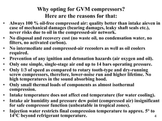
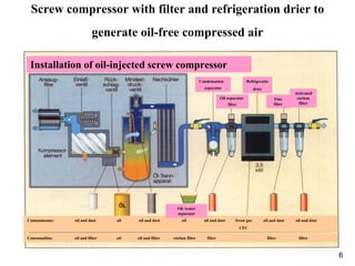
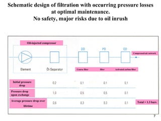
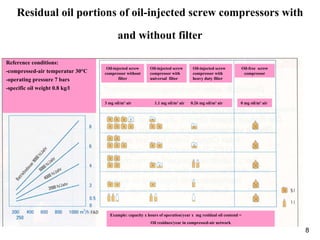
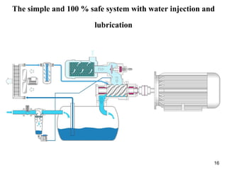
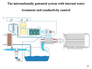
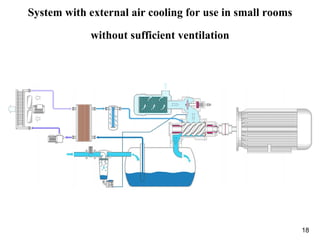
1
The World-Wide Leader In The Field Of 100 % Oil-Free
Compressor Packages
2
100 % oil-free compressors to generate compressed air in food
and beverage industries, dairies, pharmaceutical industry etc.
Generation of oil-free compressed air is required in almost all
applications, in particular, even under the aspect of ever stricter
standards, regulations, and law. Why first introducing oil into the
compression process or into the system if it has then to be removed by
filters with useless risks, energy, maintenance and disposal
expenditure. In any cases where compressed air comes in contact with
food, pharmaceutical products, clean-room production or plays an
active part in other sensitive applications, generation should be 100 %
oil-free and any remaining risk of pollution by oil and other particles
excluded. Your compressed-air generator is expected to supply
compressed air in required quality continuously with smallest energy
and maintenance expenditure and without hidden system risks. So, the
GVM system is just the right compressor system.
3
Opting for the GVM system by Nestlé group in 1995
Nestlé, one of the internationally leading groups in food production
with a comprehensive quality management system, was immediately
aware of the unique benefits of GVM system. Long-term experience
gained in using oil-free piston, rotary tooth-type and screw
compressors eased the decision for the new system. More than 35
GVM packages (even with obsolete technology, with oil-lubricated
bearings) were delivered to various Nestlé factories from 1995 till
2002. The Lünebest factory in Lüneburg purchased the first two GVM
packages with frequency control in 1998. Thanks to the good
experience, three other compressors were bought-in in 1999 and 2001.
The whole compressor station is equipped with a host control system,
providing the required compressors according to the compressed-air
demands. This means that the energy consumption has been
optimized, taking into account the availability of 2 speed-controlled
compressors.
4
Why opting for GVM compressors?
Here are the reasons for that:
• Always 100 % oil-free compressed air: quality better than intake aieven in
case of mechanical damages (bearing damages, leaky shaft seals etc.),
never risks due to oil in the compressed-air network.
• No disposal and recovery cost (no waste oil, no condensation water, no
filters, no activated carbon).
• No intermediate and compressed-air recoolers as well as oil coolers
required.
• Prevention of any ignition and detonation hazards (air oxygen and oil).
• Only one simple, single-stage air end up to 14 bars operating pressure.
• Only 1/3 of speed as compared to rotary tooth-type and dry-running
screw compressors, therefore, lower-noise run and higher lifetime. No
high temperatures in the sound absorbing hood.
• Only small thermal loads of components as almost isothermal
compression.
• Intake temperature does not affect end temperature (for water cooling).
• Intake air humidity and pressure dew point (compressed air) insignificant
for safe compressor function (unbeatable in tropical zones).
• Injection water restricts final compression temperature to approx. 5° to
14°C beyond refrigerant temperature.
5
Other reasons to opt for GVM
• Low specific power demands as almost isothermal compression. Adiabatic
compressor may reach final compression temperatures of up to 220°C in
every air end. With increased temperature, the compressed air expands
per °C temperature rise by 1/273 of tits volume thus putting a higher
resistance against the driving motor.
• Largely dimensioned slide bearings, bearing load at 11 bars only 0.3
N/mm², no wear thanks to hydrodynamic water lubrication.
• Four radial bearings and one thrust bearing.
• Up to 50 % smaller spare parts and servicing costs.
• No environmental burden, extremely low-noise run, no health risks at
workplace.
• Almost no water consumption thanks to internal control and treatment of
circulation water.
• No sediments in heat exchanger thanks to the low final temperature, even
in case of water cooling.
• Warranty granted for compressor package upon conclusion of a low-cost
full service contract over 5 years or max. 35,000 hours of operation.
6
Screw compressor with filter and refrigeration drier to
generate oil-free compressed air
Installation of oil-injected screw compressor
Condensation
separator
Oil separator
filter
Refrigeratio
drier
Fine
filter
Activated
corbon
filter
Contaminants: oil and dust oil oil and dust oil oil and dust freon gas oil and dust oil and dust
CFC
Oil /water
separator
Consumablas: oil and filter oil oil and filter corbon filter filter filter filter
7
Schematic design of filtration with occurring pressure losses
at optimal maintenance.
No safety, major risks due to oil inrush
Oil-injected compressor
Coarse filter filter Activated carbon filter
Compressed-air network
Initial pressure
drop
Pressure drop
upon exchange
Average pressure drop over
lifetime
Total = 1.3 bars
8
Residual oil portions of oil-injected screw compressors with
and without filter
Reference conditions:
-compressed-air temperatur 30°C
-operating pressure 7 bars
-specific oil weight 0.8 kg/l
Oil-injected screw
compressor without
filter
Oil-injected screw
compressor with
universal filter
Oil-injected screw
compressor with
heavy duty filter
Oil-free screw
compressor
3 mg oil/m³ air 1.1 mg oil/m³ air 0.26 mg oil/m³ air 0 mg oil/m³ air
Example: capacity x hours of operation/year x mg residual oil contend =
Oil residues/year in compressed-air network
9
Risks of filtration under changed conditions
The separation capacity of filters decreases with increasing temperatures
Winter
Summer
Residual-oil contend
Indoor
temperature
Ambient
temperatur
Air-cooled compressor Compressed-air
temperatur
Lifetime of activated carbon filter
Compressed-air temperatur in °C
Hours
Universal filter
Heavy-duty filter
Compressed-air temperatur in °C
10
Disposal routes and costs
Condensation water
Compressor Oil/Water
External cost External treatment
Management
Internal
treatment
Work, sampling
Consumables and waste
disposel
Management
11
Layout of two-stage, dry-running, adiabatic screw
compressors
Installation of oil-free screw compressor
Gearbox
Intake
filter
Intake
valve
Inter
cooler
Condensat
drain
Non return
valve
After
cooler
Condensat
drain
Contaminants: oil oil and dust
Consumables: oil oil and filter
12
Two-stage, dry-running compressor packages
- Current state of the art –
13
Sectional view – Rotary tooth-type air end
14
Sectional view – Dry-running screw compressor air end
Rotors
Cooling
Sealing
Sealing
Timing gear
15
Layout of gas and oil circuits on two-stage compressors
16
The simple and 100 % safe system with water injection and
lubrication
17
The internationally patented system with internal water
treatment and conductivity control
18
System with external air cooling for use in small rooms
without sufficient ventilation
19
The single CWG air end, only one shaft seal and four slide
bearings .
20
The single CWI air end with integral water reservoir and
water separator
21
The single CWF compressor unit with direct drive and
frequency inverter
22
The single CWI compressor unit with belt drive for
applications with small compressed-air demands
23
Safe operation of oil-free, two-stage rotary tooth-type and
screw compressors, particularly in tropical climate
Oil-free rotary tooth-type and screw compressors are running with almost adiabatic
compression processes, that is, they transform the power fed by motor into
compressed-air heat. In order to generate compression ratios of > 4, the
compression process must take place in two stages. In case of intake temperatures
of 40°C, final compression temperatures of > 220°C and more must be achieved in
every compressor air end. That is why these compressed-air temperatures must be
recooled to about 35 – 40°C in the intermediate and recooler as, otherwise, the
compressors may fail due to excess temperature. Due to these high compressed-air
temperatures, sediments by calcification and other contaminants may occur in most
cases and within a short time on the cooling water side of tubular heat exchangers
and heat transfer becomes increasingly worse. Therefore, the compressed-air
temperature rises and the compressors fail due to excess temperature. The coolers
must be dismounted and expensively cleaned. Also crucial is the compressed-air
side of coolers. Here, a significant amount of condensation water is deposited due
to the required recooling process in intermediate and recooler. This condensation
water is highly aggressive, it destroys the sealing of coolers and causes failure of
compressors in many cases as ingress of cooling water into the air ends may take
place due to rusting, causing their destruction.
24
Safe operation of oil-free, two-stage rotary tooth-type and
screw compressors, particularly in tropical climate
There is another cooling circuit in these compressors, namely the oil circuit to
lubricate and cool the bearings and gearbox. Said circuit is also equipped with a
heat exchanger to recool the circulating oil. Due to the equally high oil
temperatures, the same problems with sediments occur here as compared to the
two compressed-air coolers. The cooling circuits required for this compressor
system alone bring about high expenditure for inspection and maintenance.
How safe are these systems as regards 100 % oil-free compression?
Standard rotary tooth-type and screw compressors are running with full-load/no-
load control. That means, the intake controller is closed when the maximum
pressure is reached and a pressure below atmospheric ensues in the compressor air
end. Air with atmospheric pressure may enter here through the suction-sided shaft
seals into the compressor. In case of insufficient labyrinth seals on the gears,
ingress of oil into the compression space cannot be prevented. The same applies
for a defect of gear ventilation, here, oil may also enter through the shaft seals into
the compressor air end due to only a slight overpressure that cannot be detected
from outside. Due to the high final compression temperatures, oil carbon may
particularly settle on the compressor outlet and the downstream hot piping.
25
Abstract
• GVM features the unique 100 % oil-free
compressor system world-wide; it ensures under
any condition an ever reduced amount of
hydrocarbons in the compressed air generated as
compared to the intake air of compressors. There
is no other compressor system being able to
maintain this for ever.
• GVM grants the 100 % warranty for generation
of oil-free compressed air.

VergleichSystemeENG

  • 1.
    1 The World-Wide LeaderIn The Field Of 100 % Oil-Free Compressor Packages
  • 2.
    2 100 % oil-freecompressors to generate compressed air in food and beverage industries, dairies, pharmaceutical industry etc. Generation of oil-free compressed air is required in almost all applications, in particular, even under the aspect of ever stricter standards, regulations, and law. Why first introducing oil into the compression process or into the system if it has then to be removed by filters with useless risks, energy, maintenance and disposal expenditure. In any cases where compressed air comes in contact with food, pharmaceutical products, clean-room production or plays an active part in other sensitive applications, generation should be 100 % oil-free and any remaining risk of pollution by oil and other particles excluded. Your compressed-air generator is expected to supply compressed air in required quality continuously with smallest energy and maintenance expenditure and without hidden system risks. So, the GVM system is just the right compressor system.
  • 3.
    3 Opting for theGVM system by Nestlé group in 1995 Nestlé, one of the internationally leading groups in food production with a comprehensive quality management system, was immediately aware of the unique benefits of GVM system. Long-term experience gained in using oil-free piston, rotary tooth-type and screw compressors eased the decision for the new system. More than 35 GVM packages (even with obsolete technology, with oil-lubricated bearings) were delivered to various Nestlé factories from 1995 till 2002. The Lünebest factory in Lüneburg purchased the first two GVM packages with frequency control in 1998. Thanks to the good experience, three other compressors were bought-in in 1999 and 2001. The whole compressor station is equipped with a host control system, providing the required compressors according to the compressed-air demands. This means that the energy consumption has been optimized, taking into account the availability of 2 speed-controlled compressors.
  • 4.
    4 Why opting forGVM compressors? Here are the reasons for that: • Always 100 % oil-free compressed air: quality better than intake aieven in case of mechanical damages (bearing damages, leaky shaft seals etc.), never risks due to oil in the compressed-air network. • No disposal and recovery cost (no waste oil, no condensation water, no filters, no activated carbon). • No intermediate and compressed-air recoolers as well as oil coolers required. • Prevention of any ignition and detonation hazards (air oxygen and oil). • Only one simple, single-stage air end up to 14 bars operating pressure. • Only 1/3 of speed as compared to rotary tooth-type and dry-running screw compressors, therefore, lower-noise run and higher lifetime. No high temperatures in the sound absorbing hood. • Only small thermal loads of components as almost isothermal compression. • Intake temperature does not affect end temperature (for water cooling). • Intake air humidity and pressure dew point (compressed air) insignificant for safe compressor function (unbeatable in tropical zones). • Injection water restricts final compression temperature to approx. 5° to 14°C beyond refrigerant temperature.
  • 5.
    5 Other reasons toopt for GVM • Low specific power demands as almost isothermal compression. Adiabatic compressor may reach final compression temperatures of up to 220°C in every air end. With increased temperature, the compressed air expands per °C temperature rise by 1/273 of tits volume thus putting a higher resistance against the driving motor. • Largely dimensioned slide bearings, bearing load at 11 bars only 0.3 N/mm², no wear thanks to hydrodynamic water lubrication. • Four radial bearings and one thrust bearing. • Up to 50 % smaller spare parts and servicing costs. • No environmental burden, extremely low-noise run, no health risks at workplace. • Almost no water consumption thanks to internal control and treatment of circulation water. • No sediments in heat exchanger thanks to the low final temperature, even in case of water cooling. • Warranty granted for compressor package upon conclusion of a low-cost full service contract over 5 years or max. 35,000 hours of operation.
  • 6.
    6 Screw compressor withfilter and refrigeration drier to generate oil-free compressed air Installation of oil-injected screw compressor Condensation separator Oil separator filter Refrigeratio drier Fine filter Activated corbon filter Contaminants: oil and dust oil oil and dust oil oil and dust freon gas oil and dust oil and dust CFC Oil /water separator Consumablas: oil and filter oil oil and filter corbon filter filter filter filter
  • 7.
    7 Schematic design offiltration with occurring pressure losses at optimal maintenance. No safety, major risks due to oil inrush Oil-injected compressor Coarse filter filter Activated carbon filter Compressed-air network Initial pressure drop Pressure drop upon exchange Average pressure drop over lifetime Total = 1.3 bars
  • 8.
    8 Residual oil portionsof oil-injected screw compressors with and without filter Reference conditions: -compressed-air temperatur 30°C -operating pressure 7 bars -specific oil weight 0.8 kg/l Oil-injected screw compressor without filter Oil-injected screw compressor with universal filter Oil-injected screw compressor with heavy duty filter Oil-free screw compressor 3 mg oil/m³ air 1.1 mg oil/m³ air 0.26 mg oil/m³ air 0 mg oil/m³ air Example: capacity x hours of operation/year x mg residual oil contend = Oil residues/year in compressed-air network
  • 9.
    9 Risks of filtrationunder changed conditions The separation capacity of filters decreases with increasing temperatures Winter Summer Residual-oil contend Indoor temperature Ambient temperatur Air-cooled compressor Compressed-air temperatur Lifetime of activated carbon filter Compressed-air temperatur in °C Hours Universal filter Heavy-duty filter Compressed-air temperatur in °C
  • 10.
    10 Disposal routes andcosts Condensation water Compressor Oil/Water External cost External treatment Management Internal treatment Work, sampling Consumables and waste disposel Management
  • 11.
    11 Layout of two-stage,dry-running, adiabatic screw compressors Installation of oil-free screw compressor Gearbox Intake filter Intake valve Inter cooler Condensat drain Non return valve After cooler Condensat drain Contaminants: oil oil and dust Consumables: oil oil and filter
  • 12.
    12 Two-stage, dry-running compressorpackages - Current state of the art –
  • 13.
    13 Sectional view –Rotary tooth-type air end
  • 14.
    14 Sectional view –Dry-running screw compressor air end Rotors Cooling Sealing Sealing Timing gear
  • 15.
    15 Layout of gasand oil circuits on two-stage compressors
  • 16.
    16 The simple and100 % safe system with water injection and lubrication
  • 17.
    17 The internationally patentedsystem with internal water treatment and conductivity control
  • 18.
    18 System with externalair cooling for use in small rooms without sufficient ventilation
  • 19.
    19 The single CWGair end, only one shaft seal and four slide bearings .
  • 20.
    20 The single CWIair end with integral water reservoir and water separator
  • 21.
    21 The single CWFcompressor unit with direct drive and frequency inverter
  • 22.
    22 The single CWIcompressor unit with belt drive for applications with small compressed-air demands
  • 23.
    23 Safe operation ofoil-free, two-stage rotary tooth-type and screw compressors, particularly in tropical climate Oil-free rotary tooth-type and screw compressors are running with almost adiabatic compression processes, that is, they transform the power fed by motor into compressed-air heat. In order to generate compression ratios of > 4, the compression process must take place in two stages. In case of intake temperatures of 40°C, final compression temperatures of > 220°C and more must be achieved in every compressor air end. That is why these compressed-air temperatures must be recooled to about 35 – 40°C in the intermediate and recooler as, otherwise, the compressors may fail due to excess temperature. Due to these high compressed-air temperatures, sediments by calcification and other contaminants may occur in most cases and within a short time on the cooling water side of tubular heat exchangers and heat transfer becomes increasingly worse. Therefore, the compressed-air temperature rises and the compressors fail due to excess temperature. The coolers must be dismounted and expensively cleaned. Also crucial is the compressed-air side of coolers. Here, a significant amount of condensation water is deposited due to the required recooling process in intermediate and recooler. This condensation water is highly aggressive, it destroys the sealing of coolers and causes failure of compressors in many cases as ingress of cooling water into the air ends may take place due to rusting, causing their destruction.
  • 24.
    24 Safe operation ofoil-free, two-stage rotary tooth-type and screw compressors, particularly in tropical climate There is another cooling circuit in these compressors, namely the oil circuit to lubricate and cool the bearings and gearbox. Said circuit is also equipped with a heat exchanger to recool the circulating oil. Due to the equally high oil temperatures, the same problems with sediments occur here as compared to the two compressed-air coolers. The cooling circuits required for this compressor system alone bring about high expenditure for inspection and maintenance. How safe are these systems as regards 100 % oil-free compression? Standard rotary tooth-type and screw compressors are running with full-load/no- load control. That means, the intake controller is closed when the maximum pressure is reached and a pressure below atmospheric ensues in the compressor air end. Air with atmospheric pressure may enter here through the suction-sided shaft seals into the compressor. In case of insufficient labyrinth seals on the gears, ingress of oil into the compression space cannot be prevented. The same applies for a defect of gear ventilation, here, oil may also enter through the shaft seals into the compressor air end due to only a slight overpressure that cannot be detected from outside. Due to the high final compression temperatures, oil carbon may particularly settle on the compressor outlet and the downstream hot piping.
  • 25.
    25 Abstract • GVM featuresthe unique 100 % oil-free compressor system world-wide; it ensures under any condition an ever reduced amount of hydrocarbons in the compressed air generated as compared to the intake air of compressors. There is no other compressor system being able to maintain this for ever. • GVM grants the 100 % warranty for generation of oil-free compressed air.