Downloaded 223 times
![DNV GL – Report No. PP087423-4, Rev. 3 – www.dnvgl.com Page 12
References Number Reference
/1/
Bull, D. and Lombardo, S. “Shipping Shapes Up Preparing for New Legislation with LNG Bunkering.” Royal Haskoning DHV. 2010 [Online]. Available: http://www.royalhaskoningdhv.com/en- gb/innovation/international-innovation-day/shipping-shapes-up
/2/
Balon, T., Lowell, D., Curry, T., Van Atten, C., and Hoffman-Andrews, L. “Natural Gas for Marine Vessels: U.S. Market Opportunities.” M.J. Bradley & Associates for American Clean Skies Foundation. April 2012 [Online]. Available: http://www.cleanskies.org/wp- content/uploads/2012/04/Marine_Vessels_Final_forweb.pdf
/3/
Danish Maritime Authority. North European LNG Infrastructure Project: A feasibility study for an LNG filling station infrastructure and test of recommendations. April 2012 [Online]. Available: http://www.dma.dk/themes/LNGinfrastructureproject/Documents/Final%20Report/LNG_Full_report_Mgg_2012_04_02_1.pdf. [Accessed : 9 May 2014]
/4/
The Environmental Protection Agency. EPA Finalises More Stringent Standards for Control of Emissions from New Marine Compression-ignition Engines At or Above 30 Liters per Cylinder. Report EPA-420-F-09-068.
/5/
DNV GL “Development and Operation of Liquefied Natural Gas Bunkering Facilities” DNV GL Recommend Practice, DNVGL-RP-0006: January 2014.](https://image.slidesharecdn.com/dnvlngbunkeringstudy3sep14-140917013220-phpapp01/85/US-MARAD-LNG-Bunkering-Study-2014-21-320.jpg)
![DNV GL – Report No. PP087423-4, Rev. 3 – www.dnvgl.com Page 35
References Number Reference
/6/
“Seagas – the world’s first fuelling vessel for LNG named in Stockholm,” AGA Region Europe North. [Online]. Available: http://www.aga.com/international/web/lg/aga/like35agacom.nsf/0/3A72E0CE1A1327A5C1257B36002CCA71. [Accessed: 25-Feb-2014]
/7/
“LNG Bunkering Barge Design ,” Houlder Ltd. [Online]. Available: http://houlderltd.com/case-study/lg- bunkering-barge-concept-design-2/. [Accessed: 12-Feb-2014]
/8/
“Stockholm offers vessel-to-vessel LNG bunkering,” Marine Log, 29-Mar-2012. [Online]. Available: http://www.marinelog.com/index.php?option=com_k2&view=item&id=3819:stockholm-offers- vessel-to-vessel-lng-bunkering&Itemid=230. [Accessed: 12-Feb-2014]
/9/
“Jensen Maritime to Design First LNG Bunker Barges in U.S.,” The Maritime Executive, 24-Feb-2014. [Online]. Available: http://www.maritime-executive.com/article/Jensen-Maritime-to-Design-First-LNG-Bunker-Barges- in-US-2014-02-24/. [Accessed: 26-Feb-2014]
/10/
“TOTE to Convert Two Large Ships to LNG” [Online]. Available: http://www.fleetsandfuels.com/fuels/lng/2012/08/tote-converting-two-to-lng/. [Accessed: 17-Feb-2014]
/11/
Danish Maritime Authority, “North European LNG Infrastructure Project: A feasibility study for an LNG filling station infrastructure and test of recommendations,” April 2012 [Online]. Available: http://www.dma.dk/themes/LNGinfrastructureproject/Documents/Final%20Report/LNG_Full_report_Mgg_2012_04_02_1.pdf. [Accessed : 9-May-2014] Added sources.
/12/
“Wärtsilä to supply technology for Orca class LNG conversions - Ship Technology,” Ship Technology, 20-Feb- 2014. [Online]. Available: http://www.ship-technology.com/news/newswrtsil-to-supply-technology-for-orca- class-lng-conversions-4180688. [Accessed: 28-Feb-2014]
/13/
“Matson Signs Contract With Aker Philadelphia Shipyard For Two New ‘Aloha Class’ Containerships, First Ship To Be Named The Daniel K. Inouye,” Matson, 06-Nov-2013. [Online]. Available: http://investor.matson.com/releasedetail.cfm?ReleaseID=805068. [Accessed: 28-Feb-2014]
/14/
B. Parker, “Surfer girls, Philadelphia freedom and newbuilding finance,” Seatrade Global, 03-Feb-2014. [Online]. Available: http://www.seatrade-global.com/news/americas/surfer-girls-philadelphia-freedom-and- us-newbuilds-finance.html. [Accessed: 28-Feb-2014]
/15/
“GO GREEN - HARVEY GULF,” Harvey Gulf. [Online]. Available: http://harveygulf.com/green.html. [Accessed: 18-Feb-2014]
/16/
“Lockheed Confirms Role with Harvey Gulf,” HHPInsight.com, 14-Dec-2013. [Online]. Available: http://hhpinsight.com/marine/2013/12/lockheed-confirms-role-with-harvey-gulf/. [Accessed: 18-Feb-2014]
/17/
R. Almeida, “Washington State Ferries and DNV Explore LNG as a Fuel,” gCaptain Maritime & Offshore News, 05-Feb-2013. [Online]. Available: http://gcaptain.com/washington-state-ferries-explore/. [Accessed: 18-Feb- 2014]
/18/
R. Piellisch, “WSF’s LNG Ferries: One Step Closer,” HHPInsight.com, 25-Nov-2013. [Online]. Available: http://hhpinsight.com/marine/2013/11/wsfs-lng-ferries-said-one-step-closer/. [Accessed: 18-Feb-2014]
/19/
C. Fay, “LNG As Fuel in Passenger Vessels,” WSDOT, 24-Jan-2013. [Online]. Available: http://www.wsdot.wa.gov/NR/rdonlyres/87A58CA1-1A7D-4C9A-9740- 508989E64164/0/LNGRevisedBriefingPaperC2.pdf. [Accessed: 18-Feb-2014]
/20/
“2013 Integrated Resource Plan,” Puget Sound Energy, May 2013 [Online]. Available: http://pse.com/aboutpse/EnergySupply/Documents/IRP_2013_Chapters.pdf. [Accessed: 18-Feb-2014]](https://image.slidesharecdn.com/dnvlngbunkeringstudy3sep14-140917013220-phpapp01/85/US-MARAD-LNG-Bunkering-Study-2014-44-320.jpg)
![DNV GL – Report No. PP087423-4, Rev. 3 – www.dnvgl.com Page 36
Number Reference
/21/
M. Sedon, “LNG to power a Staten Island Ferry, saving a boatload on fuel costs,” SILive.com, 31-Dec-2012. [Online]. Available: http://www.silive.com/news/index.ssf/2012/12/staten_islands_austen_class_fe.html. [Accessed: 18-Feb-2014]
/22/
“Jensen Maritime to design LNG America’s bunker barges,” Offshore Technology, 25-Feb-2014. [Online]. Available: http://www.offshore-technology.com/news/newsjensen-maritime-to-design-lng-americas-bunker- barges-4183850. [Accessed: 27-Feb-2014]
/23/
“Shell to develop two additional natural gas for transport corridors in North America,” Shell Global, 05-Mar- 2013. [Online]. Available: http://www.shell.com/global/aboutshell/media/news-and-media- releases/2013/natural-gas-for-transport-corridors-05032012.html. [Accessed: 20-Feb-2014]
/24/
“America’s Natural Gas Highway” [Online]. Available: http://www.cleanenergyfuels.com/pdf/CE- OS.ANGH.111912.pdf. [Accessed: 20-Feb-2014]
/25/
A. Martinez, “Pivotal LNG to supply LNG to UPS facility in Jacksonville, Fla.,” 16-Jan-2014 [Online]. Available: http://www.pivotallng.com/Shared/docs/FDRLSPivotalJan2014.pdf. [Accessed: 19-Feb-2014]
/26/
Port of Los Angeles and Port of Long Beach Health Impact Assessment Scoping Meeting: Notes from Facilitated Feedback Sessions. U.S. Environmental Protection Agency, 2010 [Online]. Available: http://www.epa.gov/Region09/nepa/PortsHIA/pdfs/NotesFromFacilitatedSession.pdf. [Accessed: 21-Feb- 2014]
/27/
R. Piellisch, “Skangass for Fjord Line’s All-LNG Ferries,” HHPInsight.com, 13-Feb-2014. [Online]. Available: http://hhpinsight.com/marine/2014/02/skangass-for-fjord-lines-all-lng-ferries/. [Accessed: 27-Feb-2014]
/28/
R. Piellisch, “LNG Ferries for Two Denmark Operators,” HHPInsight.com, 08-Jul-2013. [Online]. Available: http://hhpinsight.com/marine/2013/07/lng-ferries-for-denmark-pair/. [Accessed: 27-Feb-2014]
/29/
United States President’s Commission on Critical Infrastructure Protection, Critical foundations: protecting America’s infrastructures: the report of the President’s Commission on Critical Infrastructure Protection. Commission, 1997 [Online]. Available: https://www.fas.org/sgp/library/pccip.pdf
/30/
U.S. Energy Information Administration. “U.S. boost natural gas output and use since 2005, while OCD Europe scales back.” January 14, 2014. http://www.eia.gov/todayinenergy/detail.cfm?id=14591. Accessed February 26, 2014.
/31/
Prakash, Loungani. "The Elusive Quest For Energy Independence." International Finance 12.2 (2009): 291- 299. Business Source Alumni Edition. Web. 26 Feb. 2014.
/32/
U.S. Environmental Protection Agency, “EPA Finalizes More Stringent Standards for Control of Emissions from New Marine Compression-Ignition Engines at or Above 30 Liters per Cylinder,” Dec-2009 [Online]. Available: http://www.epa.gov/nonroad/marine/ci/420f09068.pdf. [Accessed: 28-Feb-2014]
/33/
The Port of Los Angeles. “Environmental Ship Index Incentive Program Ocean-Going Vessel Incentives ” [Online]. Available: http://www.portoflosangeles.org/pdf/ESI_brochure_web_version.pdf. [Accessed: 9-May- 2014].
/34/
“Guidelines for Systems and Installations for Supply of LNG as Fuel to Ships,” The International Association of Oil and Gas Producers, OGP Draft 118683, Jun. 2013 [Online]. Available: www.ogp.org.uk/index.php/download_file/view/473/2876/. [Accessed: 14-Oct-2013]
/35/
K. L. Strom, S. A. Mathew, H. Mohn, E. Skramstad, J. Tellkamp, A. V. der Maat, S. V. Volsem, E. X. Tang, and B. Yannart, “Recommended Practices: Development and Operation of LNG Bunkering Facilities,” Draft RP - G106, Oct. 2013.
/36/
National Weather Service. “Louisiana Hurricane History.” Issued April 8, 2010.](https://image.slidesharecdn.com/dnvlngbunkeringstudy3sep14-140917013220-phpapp01/85/US-MARAD-LNG-Bunkering-Study-2014-45-320.jpg)
![DNV GL – Report No. PP087423-4, Rev. 3 – www.dnvgl.com Page 37
Number Reference
/37/
“Midwest | Global Climate Change Impacts in the United States 2009 Report.” [Online]. Available: http://nca2009.globalchange.gov/midwest#Heavy_Precipitation_and_Drought. [Accessed: 23-Feb-2014]](https://image.slidesharecdn.com/dnvlngbunkeringstudy3sep14-140917013220-phpapp01/85/US-MARAD-LNG-Bunkering-Study-2014-46-320.jpg)

![DNV GL – Report No. PP087423-4, Rev. 3 – www.dnvgl.com Page 45
be extinguished prematurely and not be sustained through the whole cloud. Hence, VCEs in open water are not considered credible events in this study.
However, in the Buncefield accident report (Ref. /41/), it is concluded that a vapor cloud passing over a dense line of trees results in rapid flame acceleration that can cause a VCE which may also transition to a detonation (Ref. /41/). This phenomenon is still under detailed investigation and can be evaluated at a later stage when more port specific information is available. Dense vegetation is not a typical feature of loading docks.
3.1.3 Failure Case Estimation
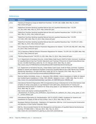
One of the key outcomes of the HAZID session is the selection of the representative failure cases that can result in a loss of containment of LNG. Various loss of containment scenarios associated with failure of LNG equipment are considered in the risk assessment based on expert discussion during the HAZID. The discussion of what scenarios are classified as significant bunkering hazards highlighted the scenarios to be included. The release scenarios assessed are discussed in detail in Section 3.3.1. The basic credible hole sizes are shown in Table 3-1.
Table 3-1: LNG Loss of Containment Hole Sizes Scenario Representative Size (Diameter Equivalent) [mm]
Small
5
Medium
25
Large
250
Rupture
Full Bore
A key feature of this list is that the hole sizes cover the full range from small leaks to full bore rupture events. The team did not screen out the worst-case events, even though they might be rare.
Each bunkering concept is evaluated for equipment failure from bunkering LNG storage tank to the client side ESD valve on the LNG tank. The bunkering storage tank is assumed to be a double walled pressurized vessel (the likelihood of equipment failure from a double walled tank is negligible, but is still considered within the study).
Also modelled is the possibility of hose rupture due to a client's ship being struck during bunkering. Tank rupture due to striking is only considered for the Ship-to-Ship (STS) bunkering concept. All other operations are done from land to the client vessel, so a cargo tank being struck by vessels is not credible.
3.1.4 Consequence Modelling
The magnitude of the potential consequences from a hydrocarbon-related failure (i.e., LNG) is estimated using DNV GL’s proprietary software package Phast Risk version 6.7. It uses discharge, dispersion, and impact models to estimate effect zones of flammable dispersion, heat radiation, and explosion overpressures. The consequence modelling includes parameters such as released material, release condition, duration, weather condition, wind speed and stability, and surface roughness.
The following scenarios are modeled for LNG releases:](https://image.slidesharecdn.com/dnvlngbunkeringstudy3sep14-140917013220-phpapp01/85/US-MARAD-LNG-Bunkering-Study-2014-54-320.jpg)
![DNV GL – Report No. PP087423-4, Rev. 3 – www.dnvgl.com Page 47
Immediate ignition has a defined probability for each release. Given that immediate ignition occurs, the majority of gas release scenarios are modelled as a jet fire. Where rainout occurs (i.e., where some liquid is present in the release), a similar event tree applies where the equivalent outcome is a pool fire (liquid only), or both pool and jet fires (where liquid rains out from the initial discharge).
Delayed ignition has a defined probability for each release. Where delayed ignition occurs, the outcome is split into flash fire and explosion scenarios. This applies equally to vapor clouds arising from gas releases or clouds flashed from liquid releases.
A BLEVE is an escalated pool fire event and is considered in the risk assessment event tree.
3.1.6 Risk Analysis
The Risk Analysis first brings together calculations from the frequency assessment and consequence modeling so that both can be presented together. DNV GL’s Phast Risk tool combines the consequences for each failure case in each wind direction, the wind probability data, the frequency of the event, and the vulnerability data to arrive at risk numbers at the different locations. The risk estimate is calculated for each frequency-consequence pair, and is summed for each location to provide the total risk for the area.
Risk analysis results are typically presented in several different ways to provide a complete picture. For this study, since there is no area specific population data, the risk metric used is independent of the population in any area and is therefore presented as the “Individual Risk”. The other form of risk measure that is commonly used is the Societal Risk, which cannot be used in this study at this stage, as it is population dependent.
Individual Risk (IR) – IR is the risk for an individual who is present at a particular location, continuously all year (i.e., 24 hours a day 7 days a week) without wearing personal protective equipment. Individual risk is the frequency at which an individual may be expected to sustain a given level of harm from the realization of specific hazards. Individual risk is often interpreted as an incident every X number of years. Examples of how to interpret individual risk are as follows:
1x10⁻³ per year is equivalent to one incident every 1,000 years
1x10⁻⁴ per year is equivalent to one incident every 10,000 years
1x10⁻⁶ per year or one incident every 1,000,000 years
These numbers do not imply that no event will occur for the specified time period. These risk levels are statistical representations of risk. They predict that an incident might occur within this average timeframe. The incident could happen tomorrow or sometime during the next 1,000 years.
Individual Risk is presented as isopleths similar to elevation contours on a map. The inner contour is the highest risk (often 10-3 or 10-4 per annum [pa]), and normally contours are plotted in declining order of magnitude circles until some very low level of risk is predicted, often 10-6 or 10-7 pa. Figure 3-6 is an example of an IR contour.](https://image.slidesharecdn.com/dnvlngbunkeringstudy3sep14-140917013220-phpapp01/85/US-MARAD-LNG-Bunkering-Study-2014-56-320.jpg)
![DNV GL – Report No. PP087423-4, Rev. 3 – www.dnvgl.com Page 58
3.2.4.2 Loading Hose Failure
The flexible loading hose is susceptible to a variety of different hazards during normal operations within the bounds of the bunkering process:
Equipment fatigue due to extreme temperature and pressure
Ship securing/mooring line failure
Striking of vessel by passing ship
Extreme weather conditions
During bunkering operations the client and bunker vessel are secured by mooring lines. In the case of striking, the mooring lines will partially absorb the impact energy. Therefore, it is assumed that only vessels with sufficient potential impact energy could cause a loss of containment by rupturing a flexible loading hose or breaching a tank. Traffic density is assumed significant and therefore a vessel striking while bunkering is a credible event.
3.2.4.3 Loss of Containment Scenarios
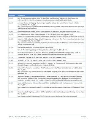
During bunkering operations, loss of containment can occur for many different reasons and in different parts of the bunkering process as described previously. In emphasis, only potential loss of containment scenarios are considered during bunkering operations. Potential failure of not-in-use equipment and failure of client side equipment (i.e., equipment after the client side emergency shutdown valve) are out of scope for this study. All equipment onshore associated with refueling (i.e., pumps, pipelines, refueling equipment) are also out of scope of this study. The loss of containment scenarios used in the risk calculation per bunkering concept are specified in Table 3-6.
Table 3-6: Loss of Containment Scenarios Scenario Description Representative Size (Diameter Equivalent) [mm]
Small
Manifold Small Release
5
Medium
Manifold Medium Release
25
Large
Manifold Large Release
Full Bore
Hose Leak
Small Hose Leak
10% of Hose Diameter
Hose Rupture
Hose Rupture
Full Bore
Cargo Tank Rupture*
Tank Rupture from Ship Striking
250
Ship Striking
Hose Rupture from Ship Striking
Full Bore
3.2.5 Detection and Isolation
The time assumed to detect and isolate is necessary to determine the inventory able to be released during a loss of containment event. Minimizing the time an event is detected and isolated will minimize the amount of inventory able to be released and hence the impact to the surroundings.
* Tank Rupture only applies to Ship-to-Ship option.](https://image.slidesharecdn.com/dnvlngbunkeringstudy3sep14-140917013220-phpapp01/85/US-MARAD-LNG-Bunkering-Study-2014-67-320.jpg)
![DNV GL – Report No. PP087423-4, Rev. 3 – www.dnvgl.com Page 81
References Number Reference
/38/
IAOGP. “Guidelines for Systems and Installations for Supply of LNG as Fuel to Ships, “International Association of Oil and Gas Producers (OGP) Draft 118683. June 2013.
/39/
DNV GL “Development and Operation of Liquefied Natural Gas Bunkering Facilities” DNV GL Recommend Practice, DNVGL-RP-0006: January 2014.
/40/
Reason, J. Human Error. Cambridge University Press. 1990.
/41/
“Buncefield Explosion Mechanism Phase 1” Steel Construction Institute, 2009. [Online] http://www.hse.gov.uk/research/rrpdf/rr718.pdf. [Accessed: 5-March-2014]
/42/
Bevi Risk Assessments, Reference Manual Bevi Risk Assessments. version 3.2 Module C, 2009.
/43/
ACDS. Advisory Committee on Dangerous Substances. Health & Safety Commission. Major Hazard Aspects of the Transport of Dangerous Substances. 1991.
/44/
NFPA. National Fire Protection Association 59A: Standard for the Production, Storage, and Handling of Liquefied Natural Gas. 2009.
/45/
Sandia National Laboratories Report SAND2008-3153. Breach and Safety Analysis of Spills over Water from Large Liquefied Natural Gas Carriers. May 2008.
/46/
Port of Ghent, Port of Antwerp, Port of Zeebrugge, Departement Mobiliteit en Openbare Werken, and Fluxys. Risk Assessment Study - Supplying Flemish Ports with LNG as a Marine Fuel: Analysis of the External Human Risks. Executive Summary. M-Tech Protec Engineering. September 2012. http://www.flanderslogistics.be/fpa/lng-summary.pdf. [Accessed on March 27, 2014]
/47/
UK HSE 1992. The Tolerability of Risk from Nuclear Power Stations, 1992.
/48/
HSE 2001. Reducing Risks, Protecting People – HSE’s Decision-Making Process, 2001.
/49/
Center for Chemical Process Safety (CCPS). Guidelines for Developing Quantitative Safety Criteria. 2009.
/50/
Los Angeles Alamanac. Vessel Traffic Los Angeles-Long Beach Harbors, 1997-2001. http://www.laalmanac.com/transport/tr47.htm. [Accessed 4-March 2014 ]
/51/
BSI. EN 12434: Cryogenic Vessels - Cryogenic Flexible Hoses. 15 October 2000.
/52/
The Hague. TNO Guideline for Quantitative Risk Assessment (Purple Book). Uijt de Haag PAM and Ale BJ, CPR 18E. December 2005.
/53/
“International Code of Safety for Ships Using Gases or Other Low-Flashpoint Fuels” [DRAFT] IGF Code, 2014.
/54/
UK HSE. Reducing Risks, Protecting People, HSE's Decision-Making Process. 2001. ISBN 0717621510.
/55/
Bjondal, L. H. LNG Bunkering-Risk Assessment and Risk Acceptance Criteria” Norwegian University of Science and Technology Department of Marine Technology. 2012.](https://image.slidesharecdn.com/dnvlngbunkeringstudy3sep14-140917013220-phpapp01/85/US-MARAD-LNG-Bunkering-Study-2014-90-320.jpg)
![DNV GL – Report No. PP087423-4, Rev. 3 – www.dnvgl.com Page 91
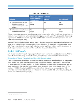
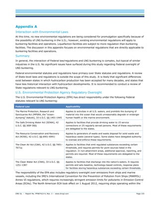
Table 4-2: Truck Carrying LNG as Cargo*
Agency with Regulatory Coverage Situation Design and Siting (including route) Security Safe Operations
6. Truck transports LNG over public roads to a standalone storage tank not on or adjacent to a navigable water of the U.S.
FMCSA
TSA
FMCSA
State/local
7. Truck transports LNG over public roads up to the perimeter of a “waterfront facility”. [Fuel transfer is in Section 3.3.3]
FMCSA
TSA
FMCSA
State/local
8. Truck transports LNG within the perimeter of a “waterfront facility”. FMCSA (dependent on circumstances) State/local FMCSA (dependent on circumstances) State/local
9. Truck transports LNG over public roads up to a bunker fuel tank not on or adjacent to a navigable water of the U.S.
State/local
TSA
State/local
State/local
10. Truck transports LNG over private roads up to the perimeter of a “waterfront facility”. [Fuel transfer is in Section 3.3.3]
State/local
DHS
State/local
11. Truck transports LNG, drives onto a vessel for carriage across a waterway.
FMCSA
USCG- vessel and the marine transfer area
TSA
USCG - vessel and the marine transfer area
USCG- vessel and the marine transfer area
State/local
State and local oversight of hazardous material transport is not identified as gaps since they are generally considered sufficiently consistent.
A significant gap with trucks carrying LNG as cargo is in Situation 8, which involves transport within the perimeter of a “waterfront facility”. Such facilities can be either private or public. Recent draft Policy Letter 02-14, issued by the USCG (Ref. /74/), if adopted, would cover design, siting, security and safe operations of trucks used to transfer LNG to vessels for use as a marine fuel:
Coast Guard jurisdiction of waterfront facilities handling LNG applies primarily over the marine transfer area for LNG as defined in 33 CFR 127.005. For the particular case at hand, this should generally be from the vessel to the last manifold or valve immediately before the tank truck or railcar and would normally include associated piping and transfer hoses. However due to this unique situation and potential for overlapping federal jurisdiction between the Coast Guard and the Department of Transportation, special consideration should be given to the Hazardous Material Regulations outlined in 49 CFR Subchapter C. Owners and operators intending to use tank trucks or rail cars as part of their LNG transfer operation should provide the COTP with a detailed list of requirements in 49 CFR Subchapter C that are applicable to their intended operation.
* Potential regulatory gaps are indicated by shading in the table.](https://image.slidesharecdn.com/dnvlngbunkeringstudy3sep14-140917013220-phpapp01/85/US-MARAD-LNG-Bunkering-Study-2014-100-320.jpg)
![DNV GL – Report No. PP087423-4, Rev. 3 – www.dnvgl.com Page 94
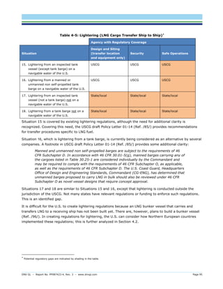
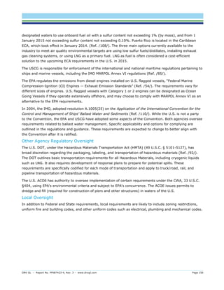
Table 4-4: Cargo Transfer (Shore–Sea or Sea-Shore) Including from Shoreside Tank Truck, Rail Car, or LNG Portable Tank*
Agency with Regulatory Coverage Situation Design and Siting (transfer location and equipment only) Security Safe Operations
14. A barge or other large vessel (the bunkering vessel) receives LNG as cargo while at berth in a navigable water of the U.S. [At another time, the LNG will be transferred from the bunkering vessel to another vessel for use as a fuel.]
USCG
State/local
USCG
State/local
USCG
State/local
Although there are no regulatory gaps identified, there would have been a gap if there was consideration for a seaside vessel to receive LNG as cargo while at berth but not in a navigable water of the U.S. This is a situation which the USCG may not have jurisdiction, although this is unclear. It is deemed unlikely to occur (but theoretically possible) based on the formal definition of a “navigable waterway” under 33 CFR 329.4 (Ref. /95/). This situation may also not be covered by FERC, who does not initiate regulation of facilities that receive, load, and unload containers filled with other cargo when LNG becomes one of the products in the container, according to 142 FERC 61 036. As such, pier facilities do not constitute 'natural gas facilities' per the Section 2 definition in the Natural Gas Act (Ref. /79/).
Regulatory Gaps in Lightering
Table 4-5 summarizes the assessed situations and relevant agencies for lightering. Lightering is not a new operation to the shipping industry or regulatory agencies. Hence, existing regulations require written transfer procedures.
* No regulatory gaps identified.](https://image.slidesharecdn.com/dnvlngbunkeringstudy3sep14-140917013220-phpapp01/85/US-MARAD-LNG-Bunkering-Study-2014-103-320.jpg)
![DNV GL – Report No. PP087423-4, Rev. 3 – www.dnvgl.com Page 114
Reference Number Reference
/56/
Foss, M. LNG Safety and Security. June 2012. [Online]. Available: http://www.beg.utexas.edu/energyecon/LNG_Safety_and_Security_Update_2012.pdf. [Accessed 8 May 2014]
/57/
DNV GL. Recommended Practice for the Development and Operation of Liquefied Natural Gas Bunkering Facilities. RP-0006:2004-1. February 2014. http://www.dnv.com/industry/oil_gas/lng_rp_document_download.asp
/58/
DNV GL. Liquefied Natural Gas (LNG) Bunkering Study: Training Requirements: Crew and Local First Responders. PP087423-3. June 2014.
/59/
International Convention for the Safety of Life at Sea (SOLAS). 1974. http://www.imo.org/About/Conventions/ListOfConventions/Pages/International-Convention-for-the-Safety- of-Life-at-Sea-(SOLAS),-1974.aspx.
/60/
International Convention on Standard of Training, Certification and Watchkeeping (STCW). 1978. as amended. http://www.admiraltylawguide.com/conven/stcw1978.html
/61/
International Maritime Organization. International Code for Construction and Equipment of Ships Carrying Liquefied Gases in Bulk: IGC Code. IMO Publishing. 1993. ISBN 9789280112771.
/62/
Maritime Safety Committee. Annex 11: Resolution MSC.285(86). Interim Guidelines on Safety for Natural Gas Fuelled Engine Installations in Ships. MSC 285(86). Adopted on 1 June 2009. http://www.imo.org/blast/blastDataHelper.asp?data_id=25897&filename=285(86).pdf
/63/
International Maritime Organization. International Code of Safety for Ships using Gases or other Low Flashpoint Fuels (IGF Code). http://regulations.justia.com/regulations/fedreg/2014/03/12/2014- 05398.html.
/64/
Thomas, C. LNG Standardisation Road Map. ISO TC 67 WG 10 Convenor-TOTAL E&P/LNG group. 2012. http://www.igu.org/IGU%20Events/wgc/wgc-2012/wgc-2012-proceedings/programme-committee- papers/programme-committee-d-pgcd/interactive-expert-showcase/lng-standardisation-road- map/@@download/download
/65/
International Organization for Standardization. ISO TC 67/DTS 118683. Guidelines for Systems and Installations for Supply of LNG as Fuel to Ships. June 4, 2013. http://www.google.com/url?sa=t&rct=j&q=&esrc=s&frm=1&source=web&cd=1&ved=0CCkQFjAA&url=http%3A%2F%2Fwww.ogp.org.uk%2Findex.php%2Fdownload_file%2Fview%2F473%2F2876%2F&ei=uNAEU5OCNee8ygOwsYG4BQ&usg=AFQjCNGqyWJ4mS50qIIX_fys_EBSq- aieg&sig2=WvnGXamBWRGRtnPZiQeYaQ&bvm=bv.61535280,d.bGQ
/66/
International Organization for Standardization. International Standard 28460. Petroleum and natural gas industries — Installation and equipment for liquefied natural gas — Ship-to-shore interface and port operations. First Ed. December 15, 2010. http://www.dma.dk/themes/LNGinfrastructureproject/Documents/European%20Committee%20for%20Standardization/ISO_28460_2010[1].pdf
/67/
The Society of International Gas Tanker and Terminal Operators (SIGTTO). Ship to Ship Transfer Guide for Petroleum, Chemicals and Liquefied Gases. SIGTTO Publications. 2013. http://www.sigtto.org/publications/publications-and-downloads
/68/
The Society of International Gas Tanker and Terminal Operators (SIGTTO). Liquefied Gas Fire Hazard Management. SIGTTO Publications. 2011. http://www.sigtto.org/publications/publications-and-downloads](https://image.slidesharecdn.com/dnvlngbunkeringstudy3sep14-140917013220-phpapp01/85/US-MARAD-LNG-Bunkering-Study-2014-123-320.jpg)
![DNV GL – Report No. PP087423-4, Rev. 3 – www.dnvgl.com Page 115
Number Reference
/69/
The Society of International Gas Tanker and Terminal Operators (SIGTTO). ESD Arrangements & Linked Ship/ Shore Systems for Liquefied Gas Carriers. SIGTTO Publications. 2009. http://www.sigtto.org/publications/publications-and-downloads
/70/
The Society of International Gas Tanker and Terminal Operators. Liquefied Gas Handling Principles on Ships and in Terminals. Third Ed. April 2000. http://www.sigtto.org/publications/publications-and-downloads
/71/
The Society of International Gas Tanker and Terminal Operators. LNG Operations in Port Areas. 2003. http://www.sigtto.org/publications/publications-and-downloads
/72/
International Association of Ports and Harbours. Press Release. Ports Work Together on Cleaner Fuels for Shipping. http://wpci.iaphworldports.org/project-in- progress/WPCI_LNG_Fuelled_Vessels_PressRelease(Mar2013).pdf. [Accessed February 13, 2014]
/73/
U.S. Department of Homeland Security. United States Coast Guard. Equivalency Determination – Design Criteria for Natural Gas Fuel Systems. CG-521 Policy Letter No. 01-12. April 9, 2012. http://www.uscg.mil/hq/cg5/cg521/docs/CG-521.PolicyLetter.01-12.pdf
/74/
U.S. Department of Homeland Security. United States Coast Guard. Draft for Public Comment: Guidance Related to Vessels and Waterfront Facilities Conducting Liquefied Natural Gas (LNG) Marine Fuel Transfer (Bunkering) Operations. CG-OES Policy Letter No. 02-14. February 2014. http://www.uscg.mil/tvncoe/Documents/default/LNGBunkering.pdf
/75/
U.S. Government Printing Office. The Electronic Code of Federal Regulations. http://www.gpo.gov/fdsys/browse/collectionCfr.action?collectionCode=CFR. [Accessed 12 September 2013]
/76/
Germanischer Lloyd. Final Report: European Maritime Safety Agency (EMSA) - Study on Standards and Rules for Bunkering of Gas-Fuelled Ships. Report No. 2012.005. Version 1.1/2013-02-15. http://www.emsa.europa.eu/emsa-documents/latest/77-publications/1714-study-on-standards-and-rules- for-bunkering-of-gas-fuelled-ships.html
/77/
VSL B.V. the Netherlands. LNG metrology. http://www.lngmetrology.info. [Accessed 2 May 2014]
/78/
Federal Energy Regulatory Commission. Office of Energy Enforcement. Energy Primer. A Handbook of Energy Market Basics. A staff report of the Division of Energy Market Oversight. July 2012. http://www.ferc.gov/market-oversight/guide/energy-primer.pdf
/79/
O’Donnell, L. “LNG Exports from the U.S.: FERC’s “Nuts and Bolts” Perspective,” LNG Export Forum North America 2012, Houston, Texas, 16 May 2012.
/80/
State of Texas, Department of Insurance. Adopted Standards: Flammable Liquids. Version 39 TexReg 2293, amended to be effective 1 April 2014. http://info.sos.state.tx.us/pls/pub/readtac$ext.TacPage?sl=R&app=9&p_dir=&p_rloc=&p_tloc=&p_ploc=&pg=1&p_tac=&ti=28&pt=1&ch=34&rl=5
/81/
State of Washington, Department of Planning and Development. 2012 Seattle Fire Code: Chapter 55: Cryogenic Fluids. 2012. http://www.seattle.gov/dpd/cs/groups/pan/@pan/documents/web_informational/s047894.pdf
/82/
Florida Administrative Register. Rule No. 69ª-3.012: Standards for the National Fire Protection Association and Other Standards Adopted. Volume 40, Number 79. 23 April 2014. https://www.flrules.org/Faw/FAWDocuments/FAWVOLUMEFOLDERS2014/4079/4079doc.pdf
/83/
New Jersey Register. Transportation of Hazardous Materials. Division of Multimodal Services, New Jersey Department of Transportation. 7 April 2014 [Online]. Available: http://www.nj.gov/transportation/about/rules/documents/AdoptionN.J.A.C.16- 49TransportationofHazardousMaterials_000.pdf [Accessed 28 May 2014]](https://image.slidesharecdn.com/dnvlngbunkeringstudy3sep14-140917013220-phpapp01/85/US-MARAD-LNG-Bunkering-Study-2014-124-320.jpg)
![DNV GL – Report No. PP087423-4, Rev. 3 – www.dnvgl.com Page 116
Number Reference
/84/
Suarez, D. Allowing LNG fueling in New York State will provide economic and environmental benefits. NGV Today. 9 December 2013 [Online]. Available: http://columbus.gov/uploadedFiles/Columbus/Departments/Finance_and_Management/Asset_Management_ Group/Fleet_Management/NGV-Today%20SEE%20PG%206%20FOR%20COLUMBUS-December-9-2013.pdf. [Accessed 12 May 2014]
/85/
U.S. Department of Homeland Security. United States Coast Guard. Draft for Public Comment: Guidelines for Liquefied Natural Gas Fuel Transfer Operations and Training of Personnel on Vessel Using Natural Gas as Fuel. CG-OES Policy Letter No. 01-14. February 2014. http://www.uscg.mil/TVNCOE/Documents/default/LNGTransferOperationsTraining.pdf
/86/
National Fire Protection Association. NFPA 59A: Standard for the Production, Storage, and Handling of Liquefied Natural Gas (LNG). 2013 Ed. ISBN: 978-145590462-4.
/87/
CSN EN 1473. Installation and equipment for liquefied natural gas - Design of onshore installations. 2007.
/88/
Louisiana Register. Title 55 Public Safety, part V. Fire Protection, Chapter 1. Preliminary Provisions. Vol. 39, No. 6. 20 June 2013.
/89/
Commission Action Matrix Agency. Title (Code) CCR, Title 24, Part 9 (2013 California Code): Amend 2013 California Fire Code. Office of the State Fire Marshal. 14 August 2012 [Online]. Available: http://www.documents.dgs.ca.gov/bsc/prpsd_chngs/2012/2nd-45Day/SFM-03-12-Pt9/Comm-Matrix-SFM- 03-12-Pt9-45Day.PDF. [Accessed 28 May 2014]
/90/
U.S. Department of Homeland Security Coast Guard. Title 33 – Navigation and Navigable Waters. 2009. http://www.gpo.gov/fdsys/pkg/CFR-2009-title33-vol1/content-detail.html.
/91/
U.S. Army Corp of Engineers. Rivers and Harbors Appropriation Act of 1899. Revised 2011. https://www.fws.gov/laws/lawsdigest/RIV1899.HTML.
/92/
U.S. Department of Transportation Pipeline and Hazardous Materials Safety Administration. U.S. Department of Transportation Seeks Public Input On Rail Car Safety Proposals. September 5, 2013. http://www.phmsa.dot.gov/portal/site/PHMSA/menuitem.6f23687cf7b00b0f22e4c6962d9c8789/?vgnextoid=23e87697ccae0410VgnVCM100000d2c97898RCRD&vgnextchannel=8fd9f08df5f3f010VgnVCM1000008355a8c0RCRD&vgnextfmt=print. [Accessed January 15, 2014]
/93/
U.S. Department of Homeland Security Coast Guard. 14 U.S.C. §2. .2012. http://www.gpo.gov/fdsys/pkg/USCODE-2012-title14/pdf/USCODE-2012-title14-partI-chap1-sec2.pdf.
/94/
U.S. Department of Homeland Security Coast Guard. 14 U.S.C. §89. 2011. http://www.gpo.gov/fdsys/granule/USCODE-2010-title14/USCODE-2010-title14-partI-chap5-sec89/content- detail.html.
/95/
U.S. Army Corp of Engineers. 33 CFR 329.4. http://www.nap.usace.army.mil/Portals/39/docs/regulatory/regs/33cfr329.pdf.
/96/
LNG World News. Jensen Maritime to Design LNG Bunker Barges, USA. [Online]. Available: http://www.lngworldnews.com/jensen-maritime-to-design-lng-bunker-barges-usa/.
/97/
NGV Global News. LNG Supply Secured for Fjord Line Cruise Ferries. [Online]. Available: http://www.ngvglobal.com/lng-supply-secured-for-fjord-line-cruise-ferries-1214.
/98/
Joslin, O. LNG in the Port of Stockholm. 14 October 2013. http://www.lngsummit.com/pdf/Ola_Joslin.pdf.
/99/
U.S. Department of Homeland Security Coast Guard. 46 CFR Ch.1. 1 October 2012. http://www.gpo.gov/fdsys/pkg/CFR-2012-title46-vol5/pdf/CFR-2012-title46-vol5-part154.pdf](https://image.slidesharecdn.com/dnvlngbunkeringstudy3sep14-140917013220-phpapp01/85/US-MARAD-LNG-Bunkering-Study-2014-125-320.jpg)
![DNV GL – Report No. PP087423-4, Rev. 3 – www.dnvgl.com Page 117
Number Reference
/100/
International Association of Oil and Gas Producers. ISO/TS 116901. Guidance on Performing Risk Assessment in the Design of Onshore LNG Installations including the Ship/Shore Interface. OGP Draft 116901. 6, February 2013. http://www.google.com/url?sa=t&rct=j&q=&esrc=s&frm=1&source=web&cd=1&ved=0CCkQFjAA&url=http%3A%2F%2Fwww.ogp.org.uk%2Findex.php%2Fdownload_file%2Fview%2F408%2F2876%2F&ei=-6kHU- mhCuG9ygPUh4H4DA&usg=AFQjCNEKN7Jf364ppTCNUKLx1TOmJw2onw&sig2=9z6B5F074VOADU92ZIJhMQ&bvm=bv.61725948,d.bGQ
/101/
Port of Gothenburg. Gothenburg Energy Port. Proposed LNG Operating Regulations including LNG Bunkering. Germanischer Lloyd SE. Revision 1.8. Last Updated: 11 February 2013. http://smtf.se/fileadmin/documents/LNG02_projektrapport_appendix_www.pdf
/102/
Aagesen, J. LNG deep-sea shipping: The outlook for LNG bunker and LNG-fuelled newbuild demand up to 2025. Lloyd Register. August 2012 [Online]. Available: http://www.lr.org/en/_images/12- 9491_LR_bunkering_study_Final_for_web_tcm155-243482.pdf. [Accessed 6 May 2014]
/103/
Danish Maritime Authority. North European LNG Infrastructure Project: A feasibility study for an LNG filling station infrastructure and test of recommendations. April 2012 [Online]. Available: http://www.dma.dk/themes/LNGinfrastructureproject/Documents/Final%20Report/LNG_Full_report_Mgg_2012_04_02_1.pdf. [Accessed : 9 May 2014]
/104/
Tellkamp, J. “Northwest Europe at LNG Bunkering Forefront.” BunkerWorld, April 2014.
/105/
Port of Rotterdam Authority. Port of Rotterdam in LNG joint venture with four ports. 25 April 2014. [Online]. Available: http://www.portofrotterdam.com/en/News/pressreleases-news/Pages/port-rotterdam-lng-joint- venture-ports.aspx. [Accessed: 8 May 2014]
/106/
Redlin, J. “Beating the Bunkering Challenge.” LNG Industry, March 2014.
/107/
Great Lakes Maritime Research Institute. MARAD Great Lakes Natural Gas Feasibility and Design Study. December 2012. http://www.glmri.org/downloads/MARADstudy2012/MARAD- GLMRI%20Great%20Lakes%20Natural%20Gas%20Study-December%202012.pdf
/108/
International Convention for the Prevention of Pollution from Ships (MARPOL). MARPOL Annex VI: Regulations for the prevention of air pollution from ships with Supplement. NTC 2008. 2013 Ed. ISBN: 9789280115604.
/109/
U.S. Environmental Protection Agency. Federal Marine Compression Ignition Engines Exhaust Emissions. June 2009. http://www.epa.gov/nonroad/marine/ci/420f09029.pdf.
/110/
International Maritime Organization. International Convention of Control and Management of Ships’ Ballast Water and Sediments.2004. ISBN 92-801-0033-5.](https://image.slidesharecdn.com/dnvlngbunkeringstudy3sep14-140917013220-phpapp01/85/US-MARAD-LNG-Bunkering-Study-2014-126-320.jpg)
![DNV GL – Report No. PP087423-4, Rev. 3 – www.dnvgl.com Page 123
qualifications based on training must be maintained within the last 5 years in accordance with STCW Regulation VI/1 in order to fulfill the duties (e.g., LNG bunkering operations) required by the personnel (Ref. /132/).
This CFR describes transfer requirements applicable to the vessel while 33 CFR Part 127 directs the designation and qualifications of the PIC as well as establishing the procedures for the LNG bunkering operations.
5.1.1.2 CG-OES Draft Policy Letters
This section includes the following CG-OES Draft Policy Letters:
No. 01-14
No. 02-14
No. 01-14 Guidelines for Liquefied Natural Gas Fuel Transfer Operations and Training of Personnel on Vessels Using Natural Gas as Fuel
This draft policy letter provides recommended guidance that aligns with existing regulations and industry best practices. It references numerous Code of Federal Regulations (CFRs) as well as international standards such as:
33 CFR Part 127, Part 155, Part 156
46 CFR Part 10, Part 11, Part 15, Part 154
STCW Chapter II and III
IMO Resolution MSC.285(86)
This draft policy letter requires the operator of the facility and/or transferring vessel for the LNG transferring operation to ensure that the vessel-specific operations manual, maintenance regimes, and emergency response plans are safely followed by the trained personnel. The operations manual is required to detail the responsibilities of personnel. Existing regulations (e.g., 46 CFR §15.405) set forth by the USGC for familiarization and basic safety training can be used for, but not limited to, LNG fuel transfer operations. Vessels that are inspected, uninspected, domestic, and foreign LNG-fueled vessels all equally share the same level of training requirements for LNG transferring operations. All personnel (especially PIC) are required to meet defined qualification levels (e.g., 46 CFR Part 10 and 11, STCW Chapter II or III, IMO Resolution MSC.285[86] Chapter 8 Section 8.2.1.2) in order to be authorized to complete the LNG transfer operation.
No. 02-14 Guidance Related to Vessels and Waterfront Facilities Conducting Liquefied Natural Gas (LNG) Marine Fuel Transfer (Bunkering) Operations
Draft Policy Letter No. 02-14 is comparable to the guidance and contents of Draft Policy Letter No. 01-14. The Draft Policy Letter No. 02-14 references numerous CFRs such as:
33 CFR Part 127, Part 155
49 CFR Part 172
o Subpart G (§172.600-§172.606) – Emergency Response Information
o Subpart H (§172.700-§172.704) – Training
o Subpart I (§172.800-§172.822) – Safety and Security Plans
The level of crew training required for facilities that use tank trucks and/or rail cars involves taking into consideration the policy as defined under ‘Training’ in 49 CFR Subpart H (§172.700-§172.704) as well as 33](https://image.slidesharecdn.com/dnvlngbunkeringstudy3sep14-140917013220-phpapp01/85/US-MARAD-LNG-Bunkering-Study-2014-132-320.jpg)
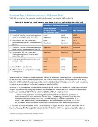
![DNV GL – Report No. PP087423-4, Rev. 3 – www.dnvgl.com Page 129
Table 5-4: Personnel Training (Ref. /123/) Personnel Training Description Minimum Training Topics
International or regulations guidelines regarding LNG fuel transfer operations
Properties hazards of LNG relevant to LNG bunkering operations and effects of mixing LNG with different properties
Risk reducing measures and safe operation of LNG fuel transfer equipment
First aid response LNG Bunkering Operations Procedures
Routine maintenance and testing procedures (including pre transfer procedures, tests, and checks)
Safe connection and disconnection procedures
Checks and procedures during LNG bunkering operations (including LNG fuel quality and properties confirmation)
SIMOPS - Management of operations other than LNG fuel transfer that can occur simultaneously with that transfer Non-Standard and Emergency Operations Training
Immediate action to be taken (according to emergency response plans) in response to emergency situations that can occur during LNG fuel transfer operations including liquid and/or vapor leakage (proper management procedures), fire or emergency breakaway
5.1.2.4 Norwegian Maritime Directorate - Regulation of 9 September 2005 No. 1218 Concerning the Construction and Operation of Gas-Fueled Passenger Ships
All training should comply with the Norwegian Maritime Directorate guidelines. This regulation assists with aligning global competence development for Category A, B, and C training (reference IMO Resolution MSC.285 [86]) for personnel on a gas-fueled passenger ship. The Norwegian Maritime Directorate must approve the structure for training of the three categories and completed training documentation (internal and external) must be available on board:
Category A - Basic: Basic competence for all officers/crew, regardless of role or function
Category B - Deck: Competence requirements for deck officers/operational deck crew
Category C - Engine: Competence requirements for engine officers/operational engine crew
Internal refresher courses are mandatory for crewmembers to assume duties on board, if such crewmembers have been absent for a continuous period of more than six months.](https://image.slidesharecdn.com/dnvlngbunkeringstudy3sep14-140917013220-phpapp01/85/US-MARAD-LNG-Bunkering-Study-2014-138-320.jpg)
![DNV GL – Report No. PP087423-4, Rev. 3 – www.dnvgl.com Page 130
5.1.2.5 DNVGL-RP-0006:2014-01 – Development and Operation of Liquefied Natural Gas Bunkering Facilities
The overall objective of this recommended practice (RP) is to ensure that:
Safety targets are met for all involved in or potentially affected by LNG bunker operations.
During normal conditions, the operations are conducted without emissions of methane to the environment. The aim is to achieve zero emissions of methane to the environment during normal operations.
A key practice is that release of natural gas into the atmosphere shall be avoided because it is for inspection or testing operations. All natural gas released during inspection shall be properly disposed without venting.
Further objectives are to increase the overall understanding of the risks associated with LNG bunkering and demonstrate how to best manage such risks.
In general, this RP recommends that all staff should obtain appropriate training to be competent in designated roles and to perform their responsibilities safely. Besides the initial training, refreshment training is important in order to maintain competence and perform safe operations. Training should include human and organizational factors.
Training requirements in Europe for personnel involved in LNG bunkering operations are structured according to the IMO Resolution MSC.285(86), STCW, the OGP Draft 118683, ADN/ADR regulations and industry codes (e.g., SIGTTO).
All personnel working with LNG bunkering operations are to be trained and authorized for working with cryogenic and flammable liquids. It is also recommended that the records of training of crew personnel shall be maintained and documented.
A direct link between Safety Management System, Risk Analysis, and Training is described.
5.1.2.6 DNV Standard for Certification No. 3.325 - Competence Related to the On Board Use of LNG as a Fuel
This standard specifies the competence requirements of a shipboard-working environment in which LNG is used as a fuel, and specifies required competence of those having to manage such operations. The standard assists with aligning global competence development for Category A, B, and C training as defined in the Interim Guidelines on Safety for Natural Gas-Fuelled Engine Installations in Ships (IMO Resolution MSC.285 [86]), and expects to support further industry initiatives.
The following categories are defined as:
Category A - Basic: Basic competence for all officers/crew, regardless of role or function
Category B - Deck: Competence requirements for deck officers/operational deck crew
Category C - Engine: Competence requirements for engine officers/operational engine crew
There are four levels of what a person has to master based on instructional design principles: knowledge, understanding, application, and integration. For each level, it is a prerequisite that the preceding level is mastered. Familiarity with similar activities aboard a conventionally fueled vessel is considered part of the skill set of the crew and is not addressed.](https://image.slidesharecdn.com/dnvlngbunkeringstudy3sep14-140917013220-phpapp01/85/US-MARAD-LNG-Bunkering-Study-2014-139-320.jpg)

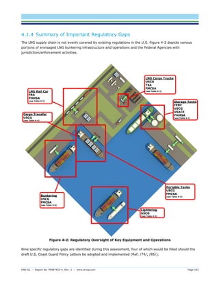
The report analyzes the feasibility and current state of liquefied natural gas (LNG) bunkering in the U.S., highlighting safety, regulatory gaps, and infrastructure challenges. It emphasizes the attractiveness of LNG as a marine fuel due to environmental benefits and cost-effectiveness but notes the need for improved standards and training for safe operations. Recommendations include conducting detailed risk assessments, developing uniform regulatory frameworks, and enhancing training programs for crew and responders involved in LNG bunkering operations.

![Emsa --final-report-bunkering-lng op-06_2012_b[1]](https://cdn.slidesharecdn.com/ss_thumbnails/emsa-final-report-bunkering-lngop062012b1-131120023037-phpapp01-thumbnail.jpg?width=640&height=640&fit=bounds)