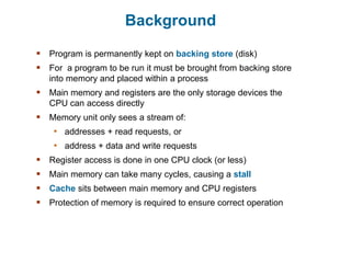
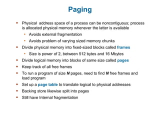
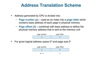
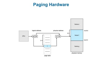
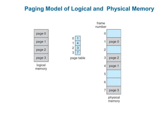
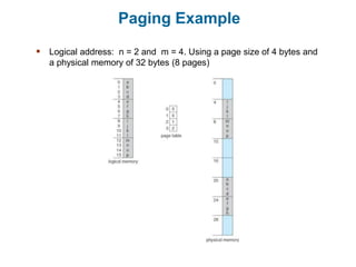
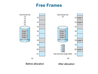
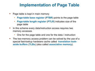
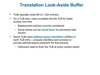
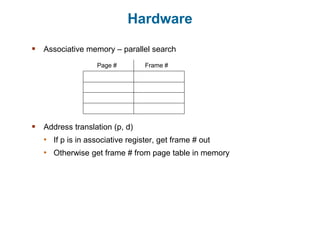
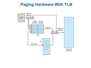
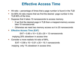
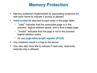
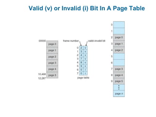
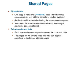
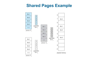
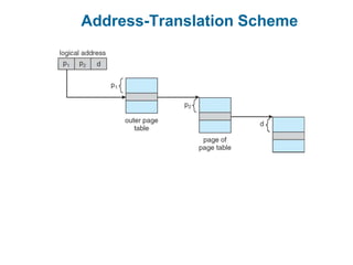
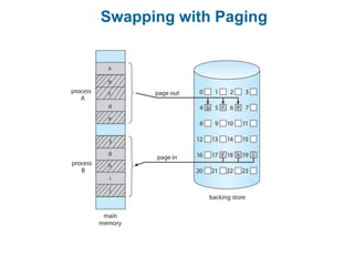
Main Memory
Outline
 Background
 Contiguous Memory Allocation
 Paging
 Structure of the Page Table
 Swapping
 Example: The Intel 32 and 64-bit Architectures
 Example: ARMv8 Architecture
Background
 Program is permanently kept on backing store (disk)
 For a program to be run it must be brought from backing store
into memory and placed within a process
 Main memory and registers are the only storage devices the
CPU can access directly
 Memory unit only sees a stream of:
• addresses + read requests, or
• address + data and write requests
 Register access is done in one CPU clock (or less)
 Main memory can take many cycles, causing a stall
 Cache sits between main memory and CPU registers
 Protection of memory is required to ensure correct operation
Memory Allocation
 Main memory must support both OS and user processes
 Limited resource, must allocate efficiently
 Contiguous allocation is one early method
 Main memory usually into two partitions:
• Resident operating system, usually held in low memory
with interrupt vector
• User processes then held in high memory
• Each process contained in single contiguous section of
memory
Contiguous Allocation
 Relocation registers used to protect user processes from each other, and
from changing operating-system code and data
• Base register contains value of smallest physical address
• Limit register contains range of logical addresses – each logical
address must be less than the limit register
• MMU maps logical address dynamically
• Can then allow actions such as kernel code being transient and
kernel changing size
Variable Partition Allocation
 Degree of multiprogramming limited by number of partitions
 Variable-partition sizes for efficiency (sized to a given process’ needs)
 Hole – block of available memory; holes of various size are scattered
throughout memory
 When a process arrives, it is allocated memory from a hole large enough
to accommodate it
 Process exiting frees its partition, adjacent free partitions combined
 Operating system maintains information about:
• (a) allocated partitions
• (b) free partitions (hole)
Dynamic Storage-Allocation Problem
 How to satisfy a request of size n from a list of free holes?
• First-fit: Allocate the first hole that is big enough
• Best-fit: Allocate the smallest hole that is big enough; must
search entire list, unless ordered by size
 Produces the smallest leftover hole
• Worst-fit: Allocate the largest hole; must also search entire
list
 Produces the largest leftover hole
 First-fit and best-fit better than worst-fit in terms of speed and
storage utilization
Dynamic Storage-Allocation Problem
 First-fit: Allocate the first hole that is big enough
 Best-fit: Allocate the smallest hole that is big enough; must
search entire list, unless ordered by size
• Produces the smallest leftover hole
 Worst-fit: Allocate the largest hole; must also search entire list
• Produces the largest leftover hole
How to satisfy a request of size n from a list of free holes?
First-fit and best-fit better than worst-fit in terms of speed and storage
utilization
Given memory partitions of 100 K, 500 K, 200 K, 300 K and 600 K (in
order) how
would each of the first fit, best fit and worst fit algorithms work place
processes of 212 K, 417 Km 112 K and 426 K (in order)? Which
algorithm makes the most efficient use of memory?
Fragmentation
 External Fragmentation – total memory space exists to satisfy a
request, but it is not contiguous
 Internal Fragmentation – allocated memory may be slightly larger
than requested memory; this size difference is memory internal to a
partition, but not being used
 First fit analysis reveals that given N blocks allocated, 0.5 N blocks
lost to fragmentation
• 1/3 may be unusable -> 50-percent rule
Fragmentation (Cont.)
 Reduce external fragmentation by compaction
• Shuffle memory contents to place all free memory together in one
large block
• Compaction is possible only if relocation is dynamic, and is done
at execution time
• I/O problem
 Latch job in memory while it is involved in I/O
 Do I/O only into OS buffers
 Now consider that backing store has same fragmentation problems
Segmentation
 Memory-management scheme that supports user view of memory
 A program is a collection of segments
 A segment is a logical unit such as:
main program
procedure
function
method
object
local variables, global variables
common block
stack
symbol table
arrays
User’s View of a Program
Logical View of Segmentation
1
3
2
4
1
4
2
3
user space physical memory space
Segmentation Architecture
 Logical address consists of a two tuple:
<segment-number, offset>
 Segment table – maps two-dimensional physical addresses; each
table entry has:
• base – contains the starting physical address where the
segments reside in memory
• limit – specifies the length of the segment
 Segment-table base register (STBR) points to the segment
table’s location in memory
 Segment-table length register (STLR) indicates number of
segments used by a program
• Segment number s is legal if s < STLR
Segmentation Hardware
Paging
 Physical address space of a process can be noncontiguous; process
is allocated physical memory whenever the latter is available
• Avoids external fragmentation
• Avoids problem of varying sized memory chunks
 Divide physical memory into fixed-sized blocks called frames
• Size is power of 2, between 512 bytes and 16 Mbytes
 Divide logical memory into blocks of same size called pages
 Keep track of all free frames
 To run a program of size N pages, need to find N free frames and
load program
 Set up a page table to translate logical to physical addresses
 Backing store likewise split into pages
 Still have Internal fragmentation
Address Translation Scheme
 Address generated by CPU is divided into:
• Page number (p) – used as an index into a page table which
contains base address of each page in physical memory
• Page offset (d) – combined with base address to define the
physical memory address that is sent to the memory unit
 For given logical address space 2m and page size 2n
Paging Hardware
Paging Model of Logical and Physical Memory
Paging Example
 Logical address: n = 2 and m = 4. Using a page size of 4 bytes and
a physical memory of 32 bytes (8 pages)
Paging -- Calculating internal fragmentation
 Page size = 2,048 bytes
 Process size = 72,766 bytes
 35 pages + 1,086 bytes
 Internal fragmentation of 2,048 - 1,086 = 962 bytes
 Worst case fragmentation = 1 frame – 1 byte
 On average fragmentation = 1 / 2 frame size
 So small frame sizes desirable?
 But each page table entry takes memory to track
 Page sizes growing over time
• Solaris supports two page sizes – 8 KB and 4 MB
Free Frames
Before allocation After allocation
Implementation of Page Table
 Page table is kept in main memory
• Page-table base register (PTBR) points to the page table
• Page-table length register (PTLR) indicates size of the
page table
 In this scheme every data/instruction access requires two
memory accesses
• One for the page table and one for the data / instruction
 The two-memory access problem can be solved by the use of a
special fast-lookup hardware cache called translation look-
aside buffers (TLBs) (also called associative memory).
Translation Look-Aside Buffer
 TLBs typically small (64 to 1,024 entries)
 On a TLB miss, value is loaded into the TLB for faster
access next time
• Replacement policies must be considered
• Some entries can be wired down for permanent fast
access
 Some TLBs store address-space identifiers (ASIDs) in
each TLB entry – uniquely identifies each process to
provide address-space protection for that process
• Otherwise need to flush the TLB at every context switch
Hardware
 Associative memory – parallel search
 Address translation (p, d)
• If p is in associative register, get frame # out
• Otherwise get frame # from page table in memory
Page # Frame #
Paging Hardware With TLB
Effective Access Time
 Hit ratio – percentage of times that a page number is found in the TLB
 An 80% hit ratio means that we find the desired page number in the
TLB 80% of the time.
 Suppose that it takes 10 nanoseconds to access memory.
• If we find the desired page in TLB then a mapped-memory access
take 10 nanoseconds
• Otherwise we need two memory access so it is 20 nanoseconds
 Effective Access Time (EAT)
EAT = 0.80 x 10 + 0.20 x 20 = 12 nanoseconds
implying 20% slowdown in access time
 Consider a more realistic hit ratio of 99%,
EAT = 0.99 x 10 + 0.01 x 20 = 10.1 nanoseconds
implying only 1% slowdown in access time.
Memory Protection
 Memory protection implemented by associating protection bit
with each frame to indicate if access is allowed
 Valid-invalid bit attached to each entry in the page table:
• “valid” indicates that the associated page is in the
process’ logical address space, and is thus a legal page
• “invalid” indicates that the page is not in the process’
logical address space
• Or use page-table length register (PTLR)
 Any violations result in a trap to the kernel
 Can also add more bits to indicate if read-only, read-write,
execute-only is allowed.
Valid (v) or Invalid (i) Bit In A Page Table
Shared Pages
 Shared code
• One copy of read-only (reentrant) code shared among
processes (i.e., text editors, compilers, window systems)
• Similar to multiple threads sharing the same process space
• Also useful for interprocess communication if sharing of
read-write pages is allowed
 Private code and data
• Each process keeps a separate copy of the code and data
• The pages for the private code and data can appear
anywhere in the logical address space
Shared Pages Example
Structure of the Page Table
 Memory structures for paging can get huge using straight-forward
methods
• Consider a 32-bit logical address space as on modern computers
• Page size of 1 KB (210)
• Page table would have 1 million entries (232 / 210)
• If each entry is 4 bytes  each process requires 16 MB of
physical address space for the page table alone
 Don’t want to allocate that contiguously in main memory
• One simple solution is to divide the page table into smaller units
 Hierarchical Paging
 Hashed Page Tables
 Inverted Page Tables
Hierarchical Page Tables
 Break up the logical address space into multiple page tables
 A simple technique is a two-level page table
 We then page the page table
Two-Level Paging Example
 A logical address (on 32-bit machine with 1K page size) is divided into:
• a page number consisting of 22 bits
• a page offset consisting of 10 bits
 Since the page table is paged, the page number is further divided into:
• a 12-bit page number
• a 10-bit page offset
 Thus, a logical address is as follows:
 where p1 is an index into the outer page table, and p2 is the
displacement within the page of the inner page table
 Known as forward-mapped page table
Address-Translation Scheme
64-bit Logical Address Space
 Even two-level paging scheme not sufficient
 If page size is 4 KB (212)
• Then page table has 252 entries
• If two level scheme, inner page tables could be 210 4-byte entries
• Address would look like
• Outer page table has 242 entries or 244 bytes
• One solution is to add a 2nd outer page table
• But in the following example the 2nd outer page table is still 234
bytes in size
 And possibly 4 memory access to get to one physical memory
location
Three-level Paging Scheme
Hashed Page Tables
 Used in architecture with address spaces > 32 bits
 The virtual page number is hashed into a page table
• This page table contains a chain of elements hashing to
the same location
 Each element contains
1. The virtual page number
2. The value of the mapped page frame
3. A pointer to the next element
 Virtual page numbers are compared in this chain searching
for a match
• If a match is found, the corresponding physical frame is
extracted
Hashed Page Tables (Cont.)
 Variation for 64-bit addresses is clustered page tables
• Similar to hashed but each entry refers to several pages
(such as 16) rather than 1
• Especially useful for sparse address spaces (where
memory references are non-contiguous and scattered)
Hashed Page Table
Inverted Page Table
 Rather than having each process keep a page table and track of all
possible logical pages, track all physical pages
 One entry for each real page of memory
 Entry consists of the virtual address of the page stored in that real
memory location, with information about the process that owns that
page
 Decreases memory needed to store each page table, but increases
time needed to search the table when a page reference occurs
 Use hash table to limit the search to one (or at most a few) page-
table entries
• TLB can accelerate access
 But how to implement shared memory?
• One mapping of a virtual address to the shared physical address
Inverted Page Table Architecture
Swapping
 A process can be swapped temporarily out of memory to a backing
store, and then brought back into memory for continued execution
• Total physical memory space of processes can exceed physical
memory
 Backing store – fast disk large enough to accommodate copies of all
memory images for all users; must provide direct access to these
memory images
 Roll out, roll in – swapping variant used for priority-based scheduling
algorithms; lower-priority process is swapped out so higher-priority
process can be loaded and executed
 Major part of swap time is transfer time; total transfer time is directly
proportional to the amount of memory swapped
 System maintains a ready queue of ready-to-run processes which
have memory images on disk
Swapping (Cont.)
 Does the swapped-out process need to swap back-in to same
physical addresses?
 Depends on address binding method
• Plus consider pending I/O to / from process memory space
 Modified versions of swapping are found on many systems (i.e.,
UNIX, Linux, and Windows)
• Swapping normally disabled
• Started if more than threshold amount of memory allocated
• Disabled again once memory demand reduced below
threshold
Schematic View of Swapping
Context Switch Time including Swapping
 If next processes to be obtain CPU is not in memory, need
to swap out a process and swap in target process
 Context switch time can then be very high
 100MB process swapping to hard disk with transfer rate of
50MB/sec
• Swap out time of 2000 milliseconds
• Plus swap in of same sized process
• Total context switch swapping component time of 4000
milliseconds (4 seconds)
Swapping (Cont.)
 Other constraints on swapping
• Pending I/O – can’t swap out as I/O would occur to
wrong process
• Or always transfer I/O to kernel space, then to I/O device
 Known as double buffering, adds overhead
 Standard swapping not used in modern operating systems
• But modified version common
 Swap only when free memory extremely low
Swapping with Paging
Swapping on Mobile Systems
 Not typically supported
• Flash memory based
 Small amount of space
 Limited number of write cycles
 Poor throughput between flash memory and CPU on mobile
platform
 Instead use other methods to free memory if low
• iOS asks apps to voluntarily relinquish allocated memory
 Read-only data thrown out and reloaded from flash if needed
 Failure to free can result in termination
• Android terminates apps if low free memory, but first writes
application state to flash for fast restart
• Both OSes support paging as discussed below

Unit-4 swapping.pptx

  • 1.
  • 2.
    Outline  Background  ContiguousMemory Allocation  Paging  Structure of the Page Table  Swapping  Example: The Intel 32 and 64-bit Architectures  Example: ARMv8 Architecture
  • 3.
    Background  Program ispermanently kept on backing store (disk)  For a program to be run it must be brought from backing store into memory and placed within a process  Main memory and registers are the only storage devices the CPU can access directly  Memory unit only sees a stream of: • addresses + read requests, or • address + data and write requests  Register access is done in one CPU clock (or less)  Main memory can take many cycles, causing a stall  Cache sits between main memory and CPU registers  Protection of memory is required to ensure correct operation
  • 4.
    Memory Allocation  Mainmemory must support both OS and user processes  Limited resource, must allocate efficiently  Contiguous allocation is one early method  Main memory usually into two partitions: • Resident operating system, usually held in low memory with interrupt vector • User processes then held in high memory • Each process contained in single contiguous section of memory
  • 5.
    Contiguous Allocation  Relocationregisters used to protect user processes from each other, and from changing operating-system code and data • Base register contains value of smallest physical address • Limit register contains range of logical addresses – each logical address must be less than the limit register • MMU maps logical address dynamically • Can then allow actions such as kernel code being transient and kernel changing size
  • 6.
    Variable Partition Allocation Degree of multiprogramming limited by number of partitions  Variable-partition sizes for efficiency (sized to a given process’ needs)  Hole – block of available memory; holes of various size are scattered throughout memory  When a process arrives, it is allocated memory from a hole large enough to accommodate it  Process exiting frees its partition, adjacent free partitions combined  Operating system maintains information about: • (a) allocated partitions • (b) free partitions (hole)
  • 7.
    Dynamic Storage-Allocation Problem How to satisfy a request of size n from a list of free holes? • First-fit: Allocate the first hole that is big enough • Best-fit: Allocate the smallest hole that is big enough; must search entire list, unless ordered by size  Produces the smallest leftover hole • Worst-fit: Allocate the largest hole; must also search entire list  Produces the largest leftover hole  First-fit and best-fit better than worst-fit in terms of speed and storage utilization
  • 8.
    Dynamic Storage-Allocation Problem First-fit: Allocate the first hole that is big enough  Best-fit: Allocate the smallest hole that is big enough; must search entire list, unless ordered by size • Produces the smallest leftover hole  Worst-fit: Allocate the largest hole; must also search entire list • Produces the largest leftover hole How to satisfy a request of size n from a list of free holes? First-fit and best-fit better than worst-fit in terms of speed and storage utilization
  • 9.
    Given memory partitionsof 100 K, 500 K, 200 K, 300 K and 600 K (in order) how would each of the first fit, best fit and worst fit algorithms work place processes of 212 K, 417 Km 112 K and 426 K (in order)? Which algorithm makes the most efficient use of memory?
  • 10.
    Fragmentation  External Fragmentation– total memory space exists to satisfy a request, but it is not contiguous  Internal Fragmentation – allocated memory may be slightly larger than requested memory; this size difference is memory internal to a partition, but not being used  First fit analysis reveals that given N blocks allocated, 0.5 N blocks lost to fragmentation • 1/3 may be unusable -> 50-percent rule
  • 11.
    Fragmentation (Cont.)  Reduceexternal fragmentation by compaction • Shuffle memory contents to place all free memory together in one large block • Compaction is possible only if relocation is dynamic, and is done at execution time • I/O problem  Latch job in memory while it is involved in I/O  Do I/O only into OS buffers  Now consider that backing store has same fragmentation problems
  • 12.
    Segmentation  Memory-management schemethat supports user view of memory  A program is a collection of segments  A segment is a logical unit such as: main program procedure function method object local variables, global variables common block stack symbol table arrays
  • 13.
  • 14.
    Logical View ofSegmentation 1 3 2 4 1 4 2 3 user space physical memory space
  • 15.
    Segmentation Architecture  Logicaladdress consists of a two tuple: <segment-number, offset>  Segment table – maps two-dimensional physical addresses; each table entry has: • base – contains the starting physical address where the segments reside in memory • limit – specifies the length of the segment  Segment-table base register (STBR) points to the segment table’s location in memory  Segment-table length register (STLR) indicates number of segments used by a program • Segment number s is legal if s < STLR
  • 16.
  • 17.
    Paging  Physical addressspace of a process can be noncontiguous; process is allocated physical memory whenever the latter is available • Avoids external fragmentation • Avoids problem of varying sized memory chunks  Divide physical memory into fixed-sized blocks called frames • Size is power of 2, between 512 bytes and 16 Mbytes  Divide logical memory into blocks of same size called pages  Keep track of all free frames  To run a program of size N pages, need to find N free frames and load program  Set up a page table to translate logical to physical addresses  Backing store likewise split into pages  Still have Internal fragmentation
  • 18.
    Address Translation Scheme Address generated by CPU is divided into: • Page number (p) – used as an index into a page table which contains base address of each page in physical memory • Page offset (d) – combined with base address to define the physical memory address that is sent to the memory unit  For given logical address space 2m and page size 2n
  • 19.
  • 20.
    Paging Model ofLogical and Physical Memory
  • 21.
    Paging Example  Logicaladdress: n = 2 and m = 4. Using a page size of 4 bytes and a physical memory of 32 bytes (8 pages)
  • 22.
    Paging -- Calculatinginternal fragmentation  Page size = 2,048 bytes  Process size = 72,766 bytes  35 pages + 1,086 bytes  Internal fragmentation of 2,048 - 1,086 = 962 bytes  Worst case fragmentation = 1 frame – 1 byte  On average fragmentation = 1 / 2 frame size  So small frame sizes desirable?  But each page table entry takes memory to track  Page sizes growing over time • Solaris supports two page sizes – 8 KB and 4 MB
  • 23.
  • 24.
    Implementation of PageTable  Page table is kept in main memory • Page-table base register (PTBR) points to the page table • Page-table length register (PTLR) indicates size of the page table  In this scheme every data/instruction access requires two memory accesses • One for the page table and one for the data / instruction  The two-memory access problem can be solved by the use of a special fast-lookup hardware cache called translation look- aside buffers (TLBs) (also called associative memory).
  • 25.
    Translation Look-Aside Buffer TLBs typically small (64 to 1,024 entries)  On a TLB miss, value is loaded into the TLB for faster access next time • Replacement policies must be considered • Some entries can be wired down for permanent fast access  Some TLBs store address-space identifiers (ASIDs) in each TLB entry – uniquely identifies each process to provide address-space protection for that process • Otherwise need to flush the TLB at every context switch
  • 26.
    Hardware  Associative memory– parallel search  Address translation (p, d) • If p is in associative register, get frame # out • Otherwise get frame # from page table in memory Page # Frame #
  • 27.
  • 28.
    Effective Access Time Hit ratio – percentage of times that a page number is found in the TLB  An 80% hit ratio means that we find the desired page number in the TLB 80% of the time.  Suppose that it takes 10 nanoseconds to access memory. • If we find the desired page in TLB then a mapped-memory access take 10 nanoseconds • Otherwise we need two memory access so it is 20 nanoseconds  Effective Access Time (EAT) EAT = 0.80 x 10 + 0.20 x 20 = 12 nanoseconds implying 20% slowdown in access time  Consider a more realistic hit ratio of 99%, EAT = 0.99 x 10 + 0.01 x 20 = 10.1 nanoseconds implying only 1% slowdown in access time.
  • 29.
    Memory Protection  Memoryprotection implemented by associating protection bit with each frame to indicate if access is allowed  Valid-invalid bit attached to each entry in the page table: • “valid” indicates that the associated page is in the process’ logical address space, and is thus a legal page • “invalid” indicates that the page is not in the process’ logical address space • Or use page-table length register (PTLR)  Any violations result in a trap to the kernel  Can also add more bits to indicate if read-only, read-write, execute-only is allowed.
  • 30.
    Valid (v) orInvalid (i) Bit In A Page Table
  • 31.
    Shared Pages  Sharedcode • One copy of read-only (reentrant) code shared among processes (i.e., text editors, compilers, window systems) • Similar to multiple threads sharing the same process space • Also useful for interprocess communication if sharing of read-write pages is allowed  Private code and data • Each process keeps a separate copy of the code and data • The pages for the private code and data can appear anywhere in the logical address space
  • 32.
  • 33.
    Structure of thePage Table  Memory structures for paging can get huge using straight-forward methods • Consider a 32-bit logical address space as on modern computers • Page size of 1 KB (210) • Page table would have 1 million entries (232 / 210) • If each entry is 4 bytes  each process requires 16 MB of physical address space for the page table alone  Don’t want to allocate that contiguously in main memory • One simple solution is to divide the page table into smaller units  Hierarchical Paging  Hashed Page Tables  Inverted Page Tables
  • 34.
    Hierarchical Page Tables Break up the logical address space into multiple page tables  A simple technique is a two-level page table  We then page the page table
  • 35.
    Two-Level Paging Example A logical address (on 32-bit machine with 1K page size) is divided into: • a page number consisting of 22 bits • a page offset consisting of 10 bits  Since the page table is paged, the page number is further divided into: • a 12-bit page number • a 10-bit page offset  Thus, a logical address is as follows:  where p1 is an index into the outer page table, and p2 is the displacement within the page of the inner page table  Known as forward-mapped page table
  • 36.
  • 37.
    64-bit Logical AddressSpace  Even two-level paging scheme not sufficient  If page size is 4 KB (212) • Then page table has 252 entries • If two level scheme, inner page tables could be 210 4-byte entries • Address would look like • Outer page table has 242 entries or 244 bytes • One solution is to add a 2nd outer page table • But in the following example the 2nd outer page table is still 234 bytes in size  And possibly 4 memory access to get to one physical memory location
  • 38.
  • 39.
    Hashed Page Tables Used in architecture with address spaces > 32 bits  The virtual page number is hashed into a page table • This page table contains a chain of elements hashing to the same location  Each element contains 1. The virtual page number 2. The value of the mapped page frame 3. A pointer to the next element  Virtual page numbers are compared in this chain searching for a match • If a match is found, the corresponding physical frame is extracted
  • 40.
    Hashed Page Tables(Cont.)  Variation for 64-bit addresses is clustered page tables • Similar to hashed but each entry refers to several pages (such as 16) rather than 1 • Especially useful for sparse address spaces (where memory references are non-contiguous and scattered)
  • 41.
  • 42.
    Inverted Page Table Rather than having each process keep a page table and track of all possible logical pages, track all physical pages  One entry for each real page of memory  Entry consists of the virtual address of the page stored in that real memory location, with information about the process that owns that page  Decreases memory needed to store each page table, but increases time needed to search the table when a page reference occurs  Use hash table to limit the search to one (or at most a few) page- table entries • TLB can accelerate access  But how to implement shared memory? • One mapping of a virtual address to the shared physical address
  • 43.
    Inverted Page TableArchitecture
  • 44.
    Swapping  A processcan be swapped temporarily out of memory to a backing store, and then brought back into memory for continued execution • Total physical memory space of processes can exceed physical memory  Backing store – fast disk large enough to accommodate copies of all memory images for all users; must provide direct access to these memory images  Roll out, roll in – swapping variant used for priority-based scheduling algorithms; lower-priority process is swapped out so higher-priority process can be loaded and executed  Major part of swap time is transfer time; total transfer time is directly proportional to the amount of memory swapped  System maintains a ready queue of ready-to-run processes which have memory images on disk
  • 45.
    Swapping (Cont.)  Doesthe swapped-out process need to swap back-in to same physical addresses?  Depends on address binding method • Plus consider pending I/O to / from process memory space  Modified versions of swapping are found on many systems (i.e., UNIX, Linux, and Windows) • Swapping normally disabled • Started if more than threshold amount of memory allocated • Disabled again once memory demand reduced below threshold
  • 46.
  • 47.
    Context Switch Timeincluding Swapping  If next processes to be obtain CPU is not in memory, need to swap out a process and swap in target process  Context switch time can then be very high  100MB process swapping to hard disk with transfer rate of 50MB/sec • Swap out time of 2000 milliseconds • Plus swap in of same sized process • Total context switch swapping component time of 4000 milliseconds (4 seconds)
  • 48.
    Swapping (Cont.)  Otherconstraints on swapping • Pending I/O – can’t swap out as I/O would occur to wrong process • Or always transfer I/O to kernel space, then to I/O device  Known as double buffering, adds overhead  Standard swapping not used in modern operating systems • But modified version common  Swap only when free memory extremely low
  • 49.
  • 50.
    Swapping on MobileSystems  Not typically supported • Flash memory based  Small amount of space  Limited number of write cycles  Poor throughput between flash memory and CPU on mobile platform  Instead use other methods to free memory if low • iOS asks apps to voluntarily relinquish allocated memory  Read-only data thrown out and reloaded from flash if needed  Failure to free can result in termination • Android terminates apps if low free memory, but first writes application state to flash for fast restart • Both OSes support paging as discussed below