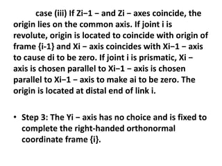
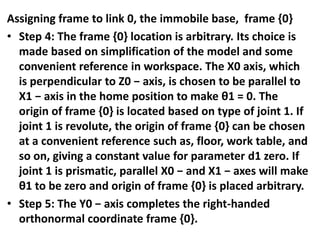
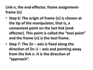
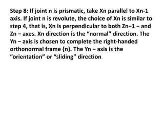
SlideShare a Scribd company logo
DH-Algorithm
• The algorithm is divided into four parts. The
first segment gives steps for labeling scheme
and the second one describes the steps for
frame assignments to intermediate links 1 to
(n-1). The third and the fourth segments give
steps for frame {0}, and frame {n} assignment;
respectively.
• Step 0: Identify and number the joints starting
with base and ending with endeffector.
Number the links from 0 to n, starting with
immobile base 0 and ending with last link n.
Step 1: Align axis Zi with axis of joint (i+1)
for i = 0, 1,……, n-1. Assigning frames to
intermediate links – link 1 to link (n-1).
For each link i repeat step 2 and 3.
Step 2: The Xi − axis is fixed perpendicular
to both Zi−1 − and Zi − axes and points
away from Zi-1. The origin of frame {i} is
located at the intersection of Zi − and Xi −
axes.
Three situations are possible:
case (i) If Zi−1 − and Zi − axes intersect, choose the
origin at the point of their intersection. The Xi − axis will
be perpendicular to the plane containing Zi−1 − and Zi −
axes. This will give ai to be zero.
case (ii) If Zi−1 − and Zi − axes are parallel or lie in
parallel planes then their common normal is not uniquely
defined. If joint i is revolute then Xi − is chosen along that
common normal, which passes through frame {i-1}. This
will fix the origin and make di zero. If joint i is prismatic,
Xi − axis is arbitrarily chosen as any convenient common
normal and the origin is located at the distal end of the
link i.
case (iii) If Zi−1 − and Zi − axes coincide, the
origin lies on the common axis. If joint i is
revolute, origin is located to coincide with origin of
frame {i-1} and Xi − axis coincides with Xi−1 − axis
to cause di to be zero. If joint i is prismatic, Xi −
axis is chosen parallel to Xi−1 − axis is chosen
parallel to Xi−1 − axis to make ai to be zero. The
origin is located at distal end of link i.
• Step 3: The Yi − axis has no choice and is fixed to
complete the right-handed orthonormal
coordinate frame {i}.
Assigning frame to link 0, the immobile base, frame {0}
• Step 4: The frame {0} location is arbitrary. Its choice is
made based on simplification of the model and some
convenient reference in workspace. The X0 axis, which
is perpendicular to Z0 − axis, is chosen to be parallel to
X1 − axis in the home position to make θ1 = 0. The
origin of frame {0} is located based on type of joint 1. If
joint 1 is revolute, the origin of frame {0} can be chosen
at a convenient reference such as, floor, work table, and
so on, giving a constant value for parameter d1 zero. If
joint 1 is prismatic, parallel X0 − and X1 − axes will make
θ1 to be zero and origin of frame {0} is placed arbitrary.
• Step 5: The Y0 − axis completes the right-handed
orthonormal coordinate frame {0}.
Link n, the end-effector, frame assignment-
frame {n}
• Step 6: The origin of frame {n} is chosen at
the tip of the manipulator, that is, a
convenient point on the last link (end-
effector). This point is called the “tool point”
and the frame {n} is the tool frame.
• Step 7: The Zn − axis is fixed along the
direction of Zn−1 − axis and pointing away
from the link n. It is the direction of
“approach”.
Step 8: If joint n is prismatic, take Xn parallel to Xn-1
axis. If joint n is revolute, the choice of Xn is similar to
step 4, that is, Xn is perpendicular to both Zn−1 − and
Zn − axes. Xn direction is the “normal” direction. The
Yn − axis is chosen to complete the right-handed
orthonormal frame {n}. The Yn − axis is the
“orientation” or “sliding” direction.

More Related Content

Similar to unit3.pptx (7)

Warshalls and floyds algorithms
Warshalls and floyds algorithmsWarshalls and floyds algorithms
Warshalls and floyds algorithms
 
Industrial Robotics By Punit Kumar Professor NIT Kurukshetra
Industrial Robotics By Punit Kumar Professor NIT KurukshetraIndustrial Robotics By Punit Kumar Professor NIT Kurukshetra
Industrial Robotics By Punit Kumar Professor NIT Kurukshetra
 
CAD Topology and Geometry Basics
CAD Topology and Geometry BasicsCAD Topology and Geometry Basics
CAD Topology and Geometry Basics
 
Lesson 13 algebraic curves
Lesson 13    algebraic curvesLesson 13    algebraic curves
Lesson 13 algebraic curves
 
Mathematics compendium for class ix
Mathematics compendium for class ixMathematics compendium for class ix
Mathematics compendium for class ix
 
Point group
Point groupPoint group
Point group
 
Polygon Fill
Polygon FillPolygon Fill
Polygon Fill
 

More from Venkateswara Babu Ravipati (12)

EG-Unit-2- Points.pptx
EG-Unit-2- Points.pptxEG-Unit-2- Points.pptx
EG-Unit-2- Points.pptx
 
EG- Unit 1.pptx
EG- Unit 1.pptxEG- Unit 1.pptx
EG- Unit 1.pptx
 
Chapter5.pptx
Chapter5.pptxChapter5.pptx
Chapter5.pptx
 
inputoutput.pptx
inputoutput.pptxinputoutput.pptx
inputoutput.pptx
 
PP ECE A Sec UNIT-1.pptx
PP ECE A Sec UNIT-1.pptxPP ECE A Sec UNIT-1.pptx
PP ECE A Sec UNIT-1.pptx
 
python unit 2.pptx
python unit 2.pptxpython unit 2.pptx
python unit 2.pptx
 
Data types.pdf
Data types.pdfData types.pdf
Data types.pdf
 
types.pdf
types.pdftypes.pdf
types.pdf
 
6-Python-Recursion PPT.pptx
6-Python-Recursion PPT.pptx6-Python-Recursion PPT.pptx
6-Python-Recursion PPT.pptx
 
cad cam and robotics.pptx
cad cam and robotics.pptxcad cam and robotics.pptx
cad cam and robotics.pptx
 
UNIT 2.pptx
UNIT 2.pptxUNIT 2.pptx
UNIT 2.pptx
 
Le and ne algorithms
Le and ne algorithmsLe and ne algorithms
Le and ne algorithms
 

Recently uploaded

RS Khurmi Machine Design Clutch and Brake Exercise Numerical Solutions
RS Khurmi Machine Design Clutch and Brake Exercise Numerical SolutionsRS Khurmi Machine Design Clutch and Brake Exercise Numerical Solutions
RS Khurmi Machine Design Clutch and Brake Exercise Numerical Solutions
Atif Razi
 
LIGA(E)11111111111111111111111111111111111111111.ppt
LIGA(E)11111111111111111111111111111111111111111.pptLIGA(E)11111111111111111111111111111111111111111.ppt
LIGA(E)11111111111111111111111111111111111111111.ppt
ssuser9bd3ba
 
CFD Simulation of By-pass Flow in a HRSG module by R&R Consult.pptx
CFD Simulation of By-pass Flow in a HRSG module by R&R Consult.pptxCFD Simulation of By-pass Flow in a HRSG module by R&R Consult.pptx
CFD Simulation of By-pass Flow in a HRSG module by R&R Consult.pptx
R&R Consult
 
Standard Reomte Control Interface - Neometrix
Standard Reomte Control Interface - NeometrixStandard Reomte Control Interface - Neometrix
Standard Reomte Control Interface - Neometrix
Neometrix_Engineering_Pvt_Ltd
 

Recently uploaded (20)

HYDROPOWER - Hydroelectric power generation
HYDROPOWER - Hydroelectric power generationHYDROPOWER - Hydroelectric power generation
HYDROPOWER - Hydroelectric power generation
 
RS Khurmi Machine Design Clutch and Brake Exercise Numerical Solutions
RS Khurmi Machine Design Clutch and Brake Exercise Numerical SolutionsRS Khurmi Machine Design Clutch and Brake Exercise Numerical Solutions
RS Khurmi Machine Design Clutch and Brake Exercise Numerical Solutions
 
LIGA(E)11111111111111111111111111111111111111111.ppt
LIGA(E)11111111111111111111111111111111111111111.pptLIGA(E)11111111111111111111111111111111111111111.ppt
LIGA(E)11111111111111111111111111111111111111111.ppt
 
A CASE STUDY ON ONLINE TICKET BOOKING SYSTEM PROJECT.pdf
A CASE STUDY ON ONLINE TICKET BOOKING SYSTEM PROJECT.pdfA CASE STUDY ON ONLINE TICKET BOOKING SYSTEM PROJECT.pdf
A CASE STUDY ON ONLINE TICKET BOOKING SYSTEM PROJECT.pdf
 
Online resume builder management system project report.pdf
Online resume builder management system project report.pdfOnline resume builder management system project report.pdf
Online resume builder management system project report.pdf
 
weather web application report.pdf
weather web application report.pdfweather web application report.pdf
weather web application report.pdf
 
Immunizing Image Classifiers Against Localized Adversary Attacks
Immunizing Image Classifiers Against Localized Adversary AttacksImmunizing Image Classifiers Against Localized Adversary Attacks
Immunizing Image Classifiers Against Localized Adversary Attacks
 
Toll tax management system project report..pdf
Toll tax management system project report..pdfToll tax management system project report..pdf
Toll tax management system project report..pdf
 
ENERGY STORAGE DEVICES INTRODUCTION UNIT-I
ENERGY STORAGE DEVICES  INTRODUCTION UNIT-IENERGY STORAGE DEVICES  INTRODUCTION UNIT-I
ENERGY STORAGE DEVICES INTRODUCTION UNIT-I
 
NO1 Pandit Amil Baba In Bahawalpur, Sargodha, Sialkot, Sheikhupura, Rahim Yar...
NO1 Pandit Amil Baba In Bahawalpur, Sargodha, Sialkot, Sheikhupura, Rahim Yar...NO1 Pandit Amil Baba In Bahawalpur, Sargodha, Sialkot, Sheikhupura, Rahim Yar...
NO1 Pandit Amil Baba In Bahawalpur, Sargodha, Sialkot, Sheikhupura, Rahim Yar...
 
Arduino based vehicle speed tracker project
Arduino based vehicle speed tracker projectArduino based vehicle speed tracker project
Arduino based vehicle speed tracker project
 
fundamentals of drawing and isometric and orthographic projection
fundamentals of drawing and isometric and orthographic projectionfundamentals of drawing and isometric and orthographic projection
fundamentals of drawing and isometric and orthographic projection
 
Explosives Industry manufacturing process.pdf
Explosives Industry manufacturing process.pdfExplosives Industry manufacturing process.pdf
Explosives Industry manufacturing process.pdf
 
Introduction to Machine Learning Unit-5 Notes for II-II Mechanical Engineering
Introduction to Machine Learning Unit-5 Notes for II-II Mechanical EngineeringIntroduction to Machine Learning Unit-5 Notes for II-II Mechanical Engineering
Introduction to Machine Learning Unit-5 Notes for II-II Mechanical Engineering
 
CFD Simulation of By-pass Flow in a HRSG module by R&R Consult.pptx
CFD Simulation of By-pass Flow in a HRSG module by R&R Consult.pptxCFD Simulation of By-pass Flow in a HRSG module by R&R Consult.pptx
CFD Simulation of By-pass Flow in a HRSG module by R&R Consult.pptx
 
Construction method of steel structure space frame .pptx
Construction method of steel structure space frame .pptxConstruction method of steel structure space frame .pptx
Construction method of steel structure space frame .pptx
 
Final project report on grocery store management system..pdf
Final project report on grocery store management system..pdfFinal project report on grocery store management system..pdf
Final project report on grocery store management system..pdf
 
Architectural Portfolio Sean Lockwood
Architectural Portfolio Sean LockwoodArchitectural Portfolio Sean Lockwood
Architectural Portfolio Sean Lockwood
 
ASME IX(9) 2007 Full Version .pdf
ASME IX(9)  2007 Full Version       .pdfASME IX(9)  2007 Full Version       .pdf
ASME IX(9) 2007 Full Version .pdf
 
Standard Reomte Control Interface - Neometrix
Standard Reomte Control Interface - NeometrixStandard Reomte Control Interface - Neometrix
Standard Reomte Control Interface - Neometrix
 

unit3.pptx

  • 2. • The algorithm is divided into four parts. The first segment gives steps for labeling scheme and the second one describes the steps for frame assignments to intermediate links 1 to (n-1). The third and the fourth segments give steps for frame {0}, and frame {n} assignment; respectively. • Step 0: Identify and number the joints starting with base and ending with endeffector. Number the links from 0 to n, starting with immobile base 0 and ending with last link n.
  • 3. Step 1: Align axis Zi with axis of joint (i+1) for i = 0, 1,……, n-1. Assigning frames to intermediate links – link 1 to link (n-1). For each link i repeat step 2 and 3. Step 2: The Xi − axis is fixed perpendicular to both Zi−1 − and Zi − axes and points away from Zi-1. The origin of frame {i} is located at the intersection of Zi − and Xi − axes. Three situations are possible:
  • 4. case (i) If Zi−1 − and Zi − axes intersect, choose the origin at the point of their intersection. The Xi − axis will be perpendicular to the plane containing Zi−1 − and Zi − axes. This will give ai to be zero. case (ii) If Zi−1 − and Zi − axes are parallel or lie in parallel planes then their common normal is not uniquely defined. If joint i is revolute then Xi − is chosen along that common normal, which passes through frame {i-1}. This will fix the origin and make di zero. If joint i is prismatic, Xi − axis is arbitrarily chosen as any convenient common normal and the origin is located at the distal end of the link i.
  • 5. case (iii) If Zi−1 − and Zi − axes coincide, the origin lies on the common axis. If joint i is revolute, origin is located to coincide with origin of frame {i-1} and Xi − axis coincides with Xi−1 − axis to cause di to be zero. If joint i is prismatic, Xi − axis is chosen parallel to Xi−1 − axis is chosen parallel to Xi−1 − axis to make ai to be zero. The origin is located at distal end of link i. • Step 3: The Yi − axis has no choice and is fixed to complete the right-handed orthonormal coordinate frame {i}.
  • 6. Assigning frame to link 0, the immobile base, frame {0} • Step 4: The frame {0} location is arbitrary. Its choice is made based on simplification of the model and some convenient reference in workspace. The X0 axis, which is perpendicular to Z0 − axis, is chosen to be parallel to X1 − axis in the home position to make θ1 = 0. The origin of frame {0} is located based on type of joint 1. If joint 1 is revolute, the origin of frame {0} can be chosen at a convenient reference such as, floor, work table, and so on, giving a constant value for parameter d1 zero. If joint 1 is prismatic, parallel X0 − and X1 − axes will make θ1 to be zero and origin of frame {0} is placed arbitrary. • Step 5: The Y0 − axis completes the right-handed orthonormal coordinate frame {0}.
  • 7. Link n, the end-effector, frame assignment- frame {n} • Step 6: The origin of frame {n} is chosen at the tip of the manipulator, that is, a convenient point on the last link (end- effector). This point is called the “tool point” and the frame {n} is the tool frame. • Step 7: The Zn − axis is fixed along the direction of Zn−1 − axis and pointing away from the link n. It is the direction of “approach”.
  • 8. Step 8: If joint n is prismatic, take Xn parallel to Xn-1 axis. If joint n is revolute, the choice of Xn is similar to step 4, that is, Xn is perpendicular to both Zn−1 − and Zn − axes. Xn direction is the “normal” direction. The Yn − axis is chosen to complete the right-handed orthonormal frame {n}. The Yn − axis is the “orientation” or “sliding” direction.