Download as PDF, PPTX
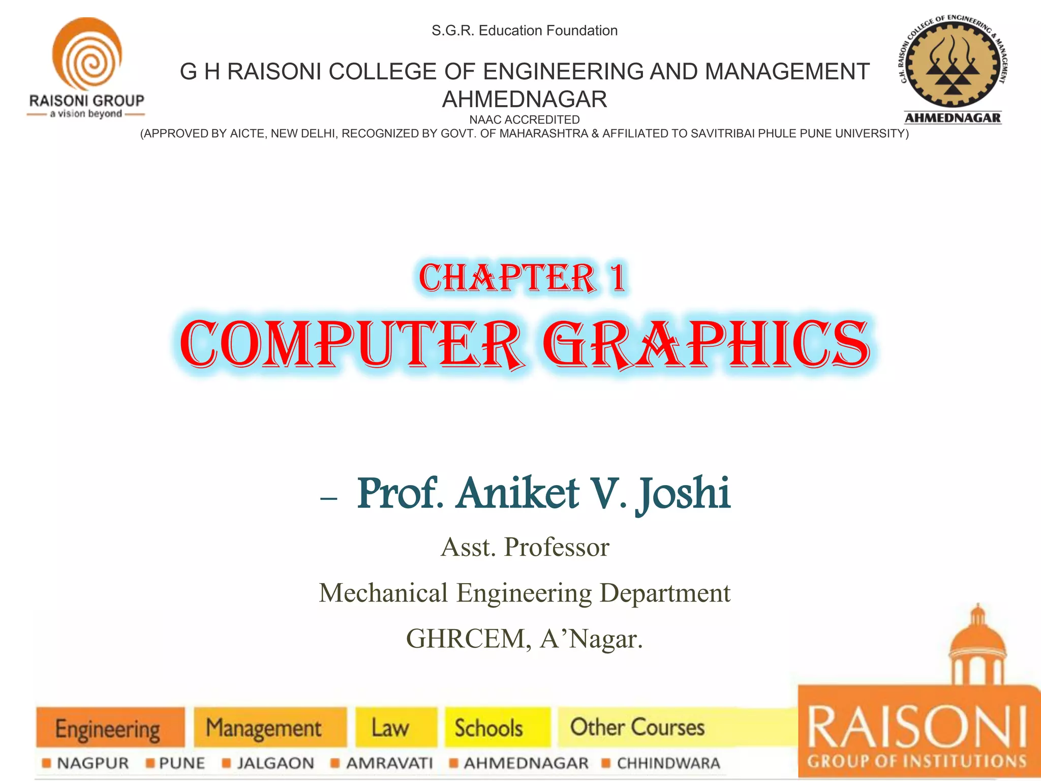
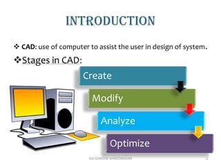
![Formulation
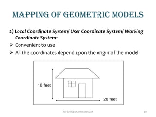
• Point can be represented as P= [x,y]
• Line can be represented as L=
• L’=L [TM] where [TM]= Transformation Matrix
AVJ GHRCEM AHMEDNAGAR 6](https://image.slidesharecdn.com/unit-icomputergraphics-210212055605/85/CAD-CAM-Automation-Unit-I-computer-graphics-6-320.jpg)
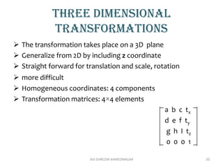
![translation
o Entity of a geometric model remains parallel to its initial
position
o Every point on geometric model moves by equal distance
T = [tx ty]
AVJ GHRCEM AHMEDNAGAR 7
A’B’C’D’ = ABCD + T](https://image.slidesharecdn.com/unit-icomputergraphics-210212055605/85/CAD-CAM-Automation-Unit-I-computer-graphics-7-320.jpg)
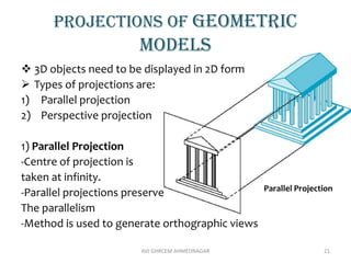
![scaling
Alters the size of an object.
It can be Uniform (equal in both X and Y directions) or non-
uniform (different in X and Y directions)
P’ = P * S
[x’ y’] = [x y]
AVJ GHRCEM AHMEDNAGAR 10](https://image.slidesharecdn.com/unit-icomputergraphics-210212055605/85/CAD-CAM-Automation-Unit-I-computer-graphics-10-320.jpg)


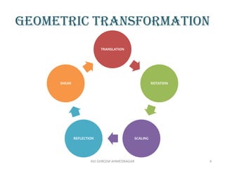
The document provides an introduction to computer graphics, focusing on computer-aided design (CAD) and interactive computer graphics. It covers various geometric transformations such as translation, rotation, scaling, reflection, and shear, including their applications and limitations. Additionally, the text discusses homogeneous coordinates, mapping of geometric models, and the types of projections needed to display 3D objects in 2D form.