This document discusses space wave propagation and the factors that affect it. It covers:
- How signal strength is reduced more quickly with increasing frequency for both good and poor earth conditions.
- Space waves travel from transmitter to receiver through both direct and reflected waves, and the net field strength is the vector sum of these waves.
- As the transmitting-receiving distance increases, the reflection results in equal but opposite-phase waves, causing the field strength to vary with the path length difference between the direct and reflected waves.
- An imperfect earth causes the field strength to oscillate around the direct wave strength and reduces the maximum amplitude of oscillations compared to a perfect earth.
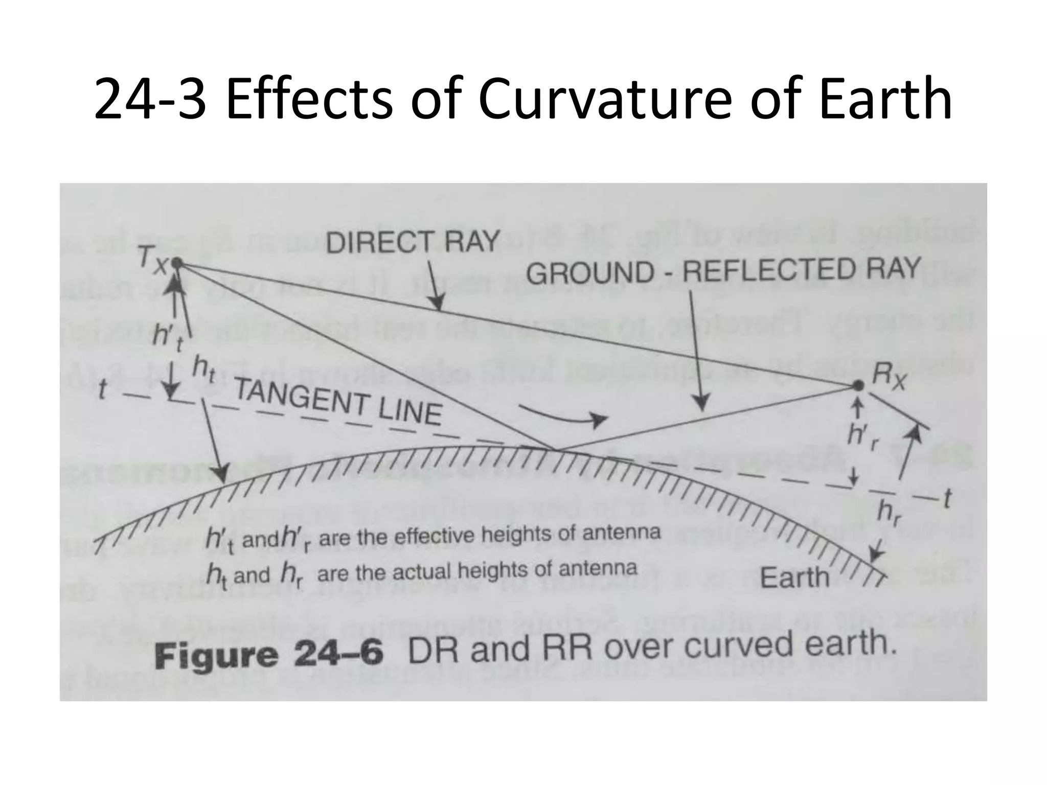
- The curvature of the


![24-2 Field Strength Relation
• R1² = (ht-hr)²+d² ..........1
• R2² = (ht+hr)²+d² ..........2
• R1 = d[1+(ht-hr)²/2d²] .......3
• R2 = d[1+ (ht+hr)²/ 2d²] .......4
• The difference in path lengths R2 and R1 is obtained to be
• R2 - R1 = [(ht+hr)² - (ht-hr)²] / 2d² = 2hthr / d ....5
• The phase difference corresponding to this path differences is
• (2π/λ) (2hthr ) / d = (4πhthr)λd radians .......6
• E = (2E0/d) sin [(2πhthr ) / λd] ........7
• When [(2πhthr ) / λd] is less than 0.5, the sine of the angle can be
replaced by the angle itself and thus 7 reduces to,
• E = (2E0/d) [(2πhthr ) / λd] = [(4πhthr)/λd²] E0 .........8](https://image.slidesharecdn.com/unit8spacewavepropagation-220527173356-49ed3be6/75/Unit-8-Space-Wave-Propagation-pptx-7-2048.jpg)


![24-3 Effects of Imperfect Earth
• In Fig. 24-5 (a), d´ is the distance at which free space field and
oscillating field for a perfectly conducting earth become equal.
• It is less than the value that makes the angle [(2πhthr) /λd] greater
than λ/6.
• It can be observed that the field strength oscillates about the value
E0 / d, which corresponds to the strength of the direct ray.
• For a perfectly conducting earth, the maximum amplitude of these
oscillation is twice of the free-space value.
• For d˃d’ , path lengths of DW and RW always differ by less than λ/6,
in such cases E falls rapidly in accordance with the proportionality
with distance square.
• For d˃d’ , the angle of incidence is so small that reflection takes
place with the reversal of phase and no change in amplitude for
both polarizations.
• The resulting field will be less than the free space values.](https://image.slidesharecdn.com/unit8spacewavepropagation-220527173356-49ed3be6/75/Unit-8-Space-Wave-Propagation-pptx-10-2048.jpg)