
Recommended
More Related Content
What's hot
What's hot (20)
Similar to Data Transmission Standards and Communication Buses
Similar to Data Transmission Standards and Communication Buses (20)
More from hiya123jes
More from hiya123jes (9)
Recently uploaded
Recently uploaded (20)
Data Transmission Standards and Communication Buses
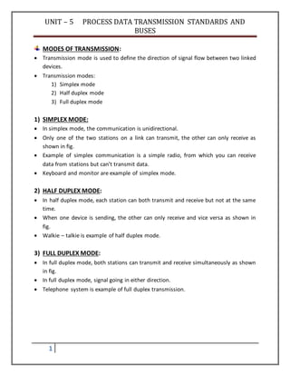
- 1. UNIT – 5 PROCESS DATA TRANSMISSION STANDARDS AND BUSES 1 MODES OF TRANSMISSION: Transmission mode is used to define the direction of signal flow between two linked devices. Transmission modes: 1) Simplex mode 2) Half duplex mode 3) Full duplex mode 1) SIMPLEX MODE: In simplex mode, the communication is unidirectional. Only one of the two stations on a link can transmit, the other can only receive as shown in fig. Example of simplex communication is a simple radio, from which you can receive data from stations but can’t transmit data. Keyboard and monitor are example of simplex mode. 2) HALF DUPLEX MODE: In half duplex mode, each station can both transmit and receive but not at the same time. When one device is sending, the other can only receive and vice versa as shown in fig. Walkie – talkie is example of half duplex mode. 3) FULL DUPLEX MODE: In full duplex mode, both stations can transmit and receive simultaneously as shown in fig. In full duplex mode, signal going in either direction. Telephone system is example of full duplex transmission.
- 2. UNIT – 5 PROCESS DATA TRANSMISSION STANDARDS AND BUSES 2 TRANSMISSION MEDIA: Transmission media is the way through which the data, information or messages can flow between the work stations. Transmission media broadly classified into two categories: 1) Guided (wired) a) Twisted pair cable b) Co – axial cable c) Fiber optic cable 2) Unguided (wireless) a) Radio wave b) Micro wave c) Infrared DIFFERENTIATE BETWEEN GUIDED AND UNGUIDED MEDIA: GUIDED MEDIA UNGUIDED MEDIA This media is directed and contained by the physical limits of the medium. This media transport electromagnetic waves without using a physical conductor. Transport signal is in the form of electric current or in the form of light. Transport signal is electromagnetic wave. E.g., twisted pair cable, co – axial cable, fiber optic cable E.g., radio wave, microwave, infrared TWISTED PAIR CABLE: Twisted pair cable comes in two forms: I. Unshielded twisted pair cable II. Shielded twisted pair cable Unshielded twisted pair cable: It is the most common type of telecommunication medium in use today.
- 3. UNIT – 5 PROCESS DATA TRANSMISSION STANDARDS AND BUSES 3 It is mostly used in telephone system. As shown in fig. twisted pair consists of two conductors, each with its own colored plastic insulation. One potential problem of UTP is that its wire can be affected by electromagnetic interference from devices, which can create a noise over wires which can damage the signal. Advantages: Low cost Easy to use Cheap and flexible Easy to install Shielded twisted pair cable: STP cable has a metal foil or braided mesh covering that enclosed each pair of insulated conductors, which are a higher quality and more protective jacket than UTP has. This gives STP excellent insulation to protect the ransmitted data from outside interference. STP is less susceptible to electrical interference and supports high transmission rates over longer distance than UTP.
- 4. UNIT – 5 PROCESS DATA TRANSMISSION STANDARDS AND BUSES 4 CO – AXIAL CABLE: Co – axial cable has better shielding than twisted pairs, so it can span longer distances at higher speed. Co – axial cable carries signals of high frequency range than twisted pair cable. In fig., co – axial cable has a central core conductor of solid or standard wire enclosed in an insulating sheath. It is enclosed in an outer conductor of metal foil, braid or a combination of two. The outer metallic wrapping serves both as a shield against noise and as the second conductor, which complete the circuit. This outer conductor is also enclosed in an insulating sheath and the whole cable is protected with a cplastic cover.
- 5. UNIT – 5 PROCESS DATA TRANSMISSION STANDARDS AND BUSES 5 Advantages: Easy to install. Flexible and easy to work with. Transmit data at longer distance and relatively high speed. Low cost. Light weight. FIBER OPTIC CABLE: Fig. shows the fiber optic cable. At the center is the glass core through which light propagates. A core is surrounded by glass cladding. A thin plastic jacket is used to protect the cladding. Two types of light sources can be used for signaling LED and lasers. Advantages: Fiber is much lighter It can’t affect noise Immunity to electromagnetic Electrical insulator
- 6. UNIT – 5 PROCESS DATA TRANSMISSION STANDARDS AND BUSES 6 Disadvantages: High cost Propagation of light is unidirectional Glass fiber is easily broken UNGUIDED MEDIA: Radio wave: Radio waves are a type of electromagnetic radiation with wavelength in the electromagnetic spectrum longer than infrared light. radio waves have frequencies from 300 GHz to as low as 3 kHz. They travel at the speed of light. Omnidirectional Does penetrate in walls Suffers from multi path interference Advantages: Can penetrate most solids and through walls Large range Disadvantages: Interference Lack of security Lower speed
- 7. UNIT – 5 PROCESS DATA TRANSMISSION STANDARDS AND BUSES 7 Micro waves: Microwaves are used for communications such as cellular telephones, satellite networks and wireless LANs. Frequency range: 1 GHz to 300 GHz Highly directional, point – to – point There are 2 types of microwaves: 1) Terrestrial microwave 2) Satellite microwave Microwave technologyisextensivelyusedfor point-to-pointtelecommunications (i.e.non-broadcast uses). Microwaves are especially suitable for this use since they are more easily focused into narrowerbeamsthanradio waves,allowing frequencyreuse;theircomparativelyhigherfrequencies allow broad bandwidth and high data transmission rates, and antenna sizes are smaller than at lower frequencies because antenna size is inversely proportional to transmitted frequency. Microwaves are used in spacecraft communication, and much of the world's data, TV, and telephonecommunicationsare transmittedlongdistancesbymicrowavesbetween ground stations and communications satellites. Microwaves are also employed in microwave ovens and in radar technology. FM Wave: Modulation Frequency modulation or FM is a form of modulation which conveys information by varying the frequency of a carrier wave; the older amplitude modulation or AM varies the amplitude of the carrier, with its frequency remaining constant. With FM, frequency deviation from the assigned carrier frequency at any instant is directly proportional to the amplitude of the input signal, determining the instantaneous frequency of the transmitted signal. Because transmitted FM signals use more bandwidth than AM signals, this form of modulation is commonly used with the higher (VHF or UHF) frequencies used by TV, the FM broadcast band, and land mobile radio systems. Armstrong's first prototype FM broadcast transmitter, located in the Empire State Building, New York City, which he used for secret tests of his system between 1934 and 1935. Licensed as experimental station W2XDG, it transmitted on 41 MHz at a power of 2 kW Pre-emphasis and de-emphasis [edit]
- 8. UNIT – 5 PROCESS DATA TRANSMISSION STANDARDS AND BUSES 8 Random noise has a triangular spectral distribution in an FM system, with the effect that noise occurs predominantly at the highest audio frequencies within the baseband. This can be offset, to a limited extent, by boosting the high frequencies before transmission and reducing them by a corresponding amount in the receiver. Reducing the high audio frequencies in the receiver also reduces the high-frequency noise. These processes of boosting and then reducing certain frequencies are known as pre-emphasis and de-emphasis, respectively Sky wave: The sky waves are the radiowaves of frequency between 2 MHz to 30 MHz. These radio waves can propagate through atmosphere and are reflected back by the ionosphere of earth’s atmosphere. Since these waves go from transmitter antenna to receiver antenna while traveling through sky, hence their propagation is known as sky wave propagation. In Figure , the path b represents the sky wave propagation. The sky waves are of practical importance at medium and high frequencies (i.e. at medium waves and short waves) for very long distance radio communication. The sky wave propagation is also known as ionosphere propagation, since the sky waves reach the receiver after reflection from the ionosphere. In a single reflection from the ionosphere, the radio waves cover a distance not more than 4000 km. With the help of sky wave propagation, a very long distance round the globe communication is possible.
- 9. UNIT – 5 PROCESS DATA TRANSMISSION STANDARDS AND BUSES 9 Space Wave Propagation : The space waves are the radio waves of very high frequency (i.e. between 30 MHz to 300 MHz or more). The space waves can travel through atmosphere from transmitter antenna to receiver antenna either directly or after reflection from ground in the earth’s troposphere region. That is why the space wave propagation is also called as tropospherical propagation. In Figure , path c represents space wave propagation. The space wave propagation is utilized in very high frequency (VHF) bands (between 30 MHz to 300 MHz), ultra high frequency (UHF) bands and microwaves. This is because, at such high frequencies, the sky wave and ground wave propagations, both fail. The space wave propagation is also called as line of sight propagation. This propagation is limited (i) to the line of sight distance and (ii) by the curvature of the earth. The line of sight distance is the distance between transmitting antenna and receiving antenna at which they can see each other, which is also called range of communication.
- 10. UNIT – 5 PROCESS DATA TRANSMISSION STANDARDS AND BUSES 10 Thus the range of communication can be increased by increasing the heights of transmitting and receiving antennas. The space wave propagation is utilized in television communication, radar communication etc The sky waves are the radiowaves of frequency between 2 MHz to 30 MHz. These radio waves can propagate through atmosphere and are reflected back by the ionosphere of earth’s atmosphere. Since these waves go from transmitter antenna to receiver antenna while traveling through sky, hence their propagation is known as sky wave propagation. In Figure , the path b represents the sky wave propagation. The sky waves are of practical importance at medium and high frequencies (i.e. at medium waves and short waves) for very long distance radio communication. The sky wave propagation is also known as ionosphere propagation, since the sky waves reach the receiver after reflection from the ionosphere. In a single reflection from the ionosphere, the radio waves cover a distance not more than 4000 km. With the help of sky wave propagation, a very long distance round the globe communication is possible.
- 11. UNIT – 5 PROCESS DATA TRANSMISSION STANDARDS AND BUSES 11 Space Wave Propagation : The space waves are the radio waves of very high frequency (i.e. between 30 MHz to 300 MHz or more). The space waves can travel through atmosphere from transmitter antenna to receiver antenna either directly or after reflection from ground in the earth’s troposphere region. That is why the space wave propagation is also called as tropospherical propagation. In Figure , path c represents space wave propagation. The space wave propagation is utilized in very high frequency (VHF) bands (between 30 MHz to 300 MHz), ultra high frequency (UHF) bands and microwaves. This is because, at such high frequencies, the sky wave and ground wave propagations, both fail. The space wave propagation is also called as line of sight propagation. This propagation is limited (i) to the line of sight distance and (ii) by the curvature of the earth. The line of sight distance is the distance between transmitting antenna and receiving antenna at which they can see each other, which is also called range of communication. Thus the range of communication can be increased by increasing the heights of transmitting and receiving antennas. The space wave propagation is utilized in television communication, radar communication etc INFRARED WAVE: remote control uses light waves just beyond the visible spectrum of light—infrared light waves—to change channels on your TV. This region of the spectrum is divided into near-, mid-, and far-infrared. The region from 8 to 15 microns (µm) is referred to by Earth scientists as thermal infrared since these wavelengths are best for studying the longwave thermal energy radiating from our planet A typical television remote control uses infrared energy at a wavelength around 940 nanometers. While you cannot "see" the light emitting from a remote, some digital and cell phone cameras are sensitive to that wavelength of radiation. INFRAREDWAVES BENEFITS Infraredwavesare veryhelpful inmedical treatmentslikesome chronichealthproblems,suchas highbloodpressure,congestiveheartfailure andrheumatoidarthritis It isalso usedinmostcameras fornightvision Disadvantages The transmittersandreceiversmustbe closelyalignedtocommunicate bybeingdirectlyinsightof
- 12. UNIT – 5 PROCESS DATA TRANSMISSION STANDARDS AND BUSES 12 each other performance will dropoff if the distance tothe receiverisoutof range forthe infrareddevice Andwithlarge areas itrequire multiple emitterpanels SERIAL AND PARALLEL TRANSMISSION STANDARDS: Types of serial transmission standard: RS – 232 RS – 422 RS – 485 RS – 232: RS232- “RECOMMENDED STANDARDS-232” RS-232 is a standard communication protocol for linking computer and its peripheral devices to allow serial data exchange. RS-232 allows only for one transmitter & one receiver. RS-232 uses full-duplex transmission method. RS-232C, EIA RS-232, or simply RS-232, refers to the same standard defined by the Electronic Industries Association in 1969 for serial communication. DTE and DCE DTE stands for Data Terminal Equipment. A computer is a DTE. DCE stands for Data Communication Equipment. A modem is a DCE.
- 13. UNIT – 5 PROCESS DATA TRANSMISSION STANDARDS AND BUSES 13
- 14. UNIT – 5 PROCESS DATA TRANSMISSION STANDARDS AND BUSES 14 DCE-A DCE stands for data communication equipments. It sits between the DTE and data transmission circuit for example modem. A DCE device uses a female connector which has holes on the surface to hold male connector. DTE normally comes with a Male Connector, while DCE comes with a Female Connector. However, that is not always true. Use the simple way below to confirm: Measure Pin 3 and Pin 5 of a DB-9 Connector with a Volt Meter, if you get a voltage of -3V to -15V, then it is a DTE device. If the voltage is on Pin 2, then it is a DCE device.
- 15. UNIT – 5 PROCESS DATA TRANSMISSION STANDARDS AND BUSES 15 TxD (Transmitted data): this line carries serial data from the DTE to the corresponding pin on the DCE.
- 16. UNIT – 5 PROCESS DATA TRANSMISSION STANDARDS AND BUSES 16 RxD (Received data): this line carries serial data from the DCE to the corresponding pin on the DTE. RTS (Request to send): This line is placed active when the DTE requests permission to send data. The DCE then activates the CTS for hardware data flow control. CTS (Clear to send): When the modem activates the CTS, it informs the DTE that itn is now safe to send data. DSR (Data set ready): The DTE ready line is an indication from the DCE to the DTE that the modem is ready. DCD (Data carrier detect): This is also called the received line signal detector. It is activated by the modem when it receives a remote carrier and remains activated for the duration of the link. DTR (Data terminal ready): DTR indicates the readiness of the DTE. This signal is turned ON by the DTE when it is ready to transmit or receive data from the DCE. DTR must be ON before the DCE can assert DSR. RI (Ring indicator): RI, when asserted, indicates that a ringing signal is being received on the communications channel. RS – 232 transmitter is required to produce voltages in the range +/- 5 V to +/- 25 V as follows: Logic 1: -5 V to -25 V Logic 0: +5 V to +25 V Undefined logic level: +5 V to -5 V At RS – 232 receiver, the following voltage levels are defined: Logic 1: -3 V to -25 V Logic 0: +3 V to +25 V Undefined logic level: -3 V to +3 V RS – 422:
- 17. UNIT – 5 PROCESS DATA TRANSMISSION STANDARDS AND BUSES 17 COMPARISON OF ALL STANDARDS: Types of parallel transmission standard: IEEE 488 IEEE 1284 VARIOUS TYPES INDUSTRIAL INSTRUMENTATION COMMUNICATION BUSES:
- 18. UNIT – 5 PROCESS DATA TRANSMISSION STANDARDS AND BUSES 18 Foundation Field Bus Profibus IEEE488 (GPIB) HART FOUNDATION FIELD BUS: It is an all digital, serial two – way communication system that is used in a plant or factory automation environment. Foundation fieldbus technology is mostly used in process industries bus has been recently been implemented in power plants. There are two types of foundation field bus developed to meet different needs of process automation environment. 1) Foundation fieldbus H1: It operates at 31.25 kbps and is generally used to connect to field devices and host systems. It provides communication and power over standard twisted pair wiring. H1 is currently the most common type. 2) Foundation fieldbus HSE (High Speed Ethernet): It operates at 100 Mbps and generally connects input / output subsystems, host systems, linking devices. It doesn’t currently provide power over the cable. Foundation fieldbus is used in process control and monitoring. Process control refers to continuous processes like flow control, temperature control, tank level control. These processes are found in place like oil refineries, chemical plants and paper mills. Foundation fieldbus can also be used for monitoring over long distances. PROFIBUS: PROFIBUS (Process Field Bus) is a standard for field bus communication in automation technology. Profibus FMS is used for (non deterministic) communication of data between Profibus Masters. Profibus DP is a protocol made for (deterministic) communication between Profibus masters and their remote I/O slaves.
- 19. UNIT – 5 PROCESS DATA TRANSMISSION STANDARDS AND BUSES 19 There are three variations of PROFIBUS in use today; the most commonly used PROFIBUS DP. 1) PROFIBUS FMS (Field message specification): It was designed to communicate between programmable controllers and PCs, sending complex information between them. This protocol was not appropriate for less complex messages or communication on a wider, more complicated network. 2) PROFIBUS DP (Decentralized Peripherals): It is used to operate sensors and actuators via a centralized controller in production (factory) automation applications. 3) PROFIBUS PA (Process Automation): It is used to monitor measuring equipment via a process control system in process automation applications. This variant is designed for use in explosion/hazardous areas (Ex-zone 0 and 1). PA uses the same protocol as DP, and can be linked to a DP network using a coupler device. The much faster DP acts as a backbone network for transmitting process signals to the controller. This means that DP and PA can work tightly together, especially in hybrid applications where process and factory automation networks operate side by side. IEEE 488 (GPIB): IEEE 488 bus was developed to connect and control programmable instruments. It would provide a standard interface for communication between instruments from different sources. Hewlett – Packard originally developed the interfacing technique and called it HP – IB. The IEEE (Institute of Electrical and Electronic Engineers) committee renamed it GPIB (General Purpose Interface Bus). Purpose of this protocol is to provide a standardized parallel communication method to connect 2 to 15 devices to increase data transfer. Almost any instrument can be used with a special connector. Each cable has a combined male and female connector to allow parallel connection of cables at any device. Some key features of the IEEE 488 interface are:
- 20. UNIT – 5 PROCESS DATA TRANSMISSION STANDARDS AND BUSES 20 24 wire bus and allows up to 15 devices may be connected to one bus. Total bus length may be up to 20 m and the distance between devices may be up to 2 m. 1 byte of digital information is sent in parallel each time. Maximum data rate is 1 Mbyte/s. There are 3 types of devices that can be connected to the IEEE 488 bus. A listener is a device that can receive data from the bus when instructed by the controller. A talker transmits data on to bus when instructed. The controller can set up a talker and a group of listeners so that it is possible to send data between groups of devices as well. It is possible to have several controllers on the bus but only one may be active at any given time. HART protocol: The HART (Highway Addressable Remote Transducer) protocol is a typical smart instrumentation fieldbus that can operate in a hybrid 4 – 20 mA digital fashion. This protocol was originally developed by Rosemount. Its main advantage is that it enables an instrument engineer to keep existing 4 – 20 mA instrumentation cabling and to use simultaneously, the same wires to carry digital information superimposed on the analog signal. This enables most companies to capitalize on their existing investment in 4 – 20 mA instrumentation cabling and associated systems and to add further capability of HART without adding major costs. HART is a hybrid analog and digital protocol. Two individual frequencies of 1200Hz and 2200Hz representing digits 1 and 0 respectively, are used. There are 2 operational modes of HART instruments: 1) Analog digital mode (poll/response mode or point to point mode): In this mode, the digital signals are overlaid on the 4 – 20 mA loop current. For example, pressure can be sent as 4 – 20 mA, representing a range of pressures and temperature can be sent digitally over same wires.
- 21. UNIT – 5 PROCESS DATA TRANSMISSION STANDARDS AND BUSES 21 2) Multidrop mode (burst mode): In this mode, only digital signals are used. The analog loop current is fixed at 4 mA.