
Recommended
More Related Content
What's hot
What's hot (20)
Similar to Adaptive Equalization
Similar to Adaptive Equalization (20)
Recently uploaded
Recently uploaded (20)
Adaptive Equalization
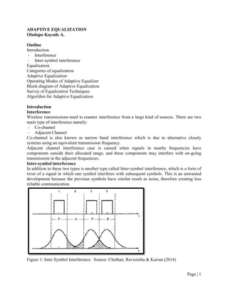
- 1. Page | 1 ADAPTIVE EQUALIZATION Oladapo Kayode A. Outline Introduction - Interference - Inter-symbol interference Equalization Categories of equalization Adaptive Equalization Operating Modes of Adaptive Equalizer Block diagram of Adaptive Equalization Survey of Equalization Techniques Algorithm for Adaptive Equalization Introduction Interference Wireless transmissions need to counter interference from a large kind of sources. There are two main type of interference namely: - Co-channel - Adjacent Channel Co-channel is also known as narrow band interference which is due to alternative closely systems using an equivalent transmission frequency. Adjacent channel interference case is caused when signals in nearby frequencies have components outside their allocated range, and these components may interfere with on-going transmission in the adjacent frequencies. Inter-symbol interference In addition to these two types is another type called Inter-symbol interference, which is a form of twist of a signal in which one symbol interferes with subsequent symbols. This is an unwanted development because the previous symbols have similar result as noise, therefore creating less reliable communication. Figure 1: Inter Symbol Interference. Source: Chethan, Ravisimha & Kurian (2014)
- 2. Page | 2 Equalization This is a commonly used strategy for resisting inter symbol Interference. Since Inter-symbol interference has been recognized as the main blockage to high speed data transmission over mobile radio channels. Equalization involves the gathering of the dispersed symbol energy into its original time interval. Categories of equalization Equalizers are used in conquering the adverse effects of the channel and can be divided into two broad categories: 1. Maximum Likelihood Sequence Estimation (MLSE): This consist the making of channel impulse response measurement and then giving a means for receiver adjustment to the transmission area. 2. Equalization with filters which make use of filters to reimburse the distorted pulses. Depending on whether the timing is variant or invariant, equalizer can be categorize as 3. Preset equalizer assume that the channel is time invariant; try to find H(f) and then design an equalizer depending on H(f). 4. Adaptive equalizer assume that the channel is time variant and also design an equalizer filter with varying filter coefficients in time according to the change of channel which try to eliminate ISS and additive noise at each time. This channel is assumed to be slow. Adaptive Equalization As a mobile channel fades randomly and varied in time, the equalizer must track that the time varying characteristics of the mobile channel, and thus are called adaptive equalizers. It is an equalizer that automatically adapts to time-varying properties of the mobile communication channel. The following are the working principles of adaptive equalizers: 1. Application of the received signal to receive filter. In this place, receive filter is not linked filter. Because the channel impulse response is unknown. The receive filter in here is just a low‐pass filter that refuse to accept all out of band noise. 2. The output of the receiver filter is pictured at the symbol rate. 3. Sampled signal is applied to adaptive transversal filter equalizer. Transversal filters are actually FIR discrete time filters. 4. The object is to adapt the coefficients to minimize the noise and inter-symbol interference (depending on the type of equalizer) at the output. 5. The adaptation of the equalizer is driven by an error signal. Operating Modes of Adaptive Equalizer Adaptive equalizer can operate in two modes: a. Decision Directed Mode which indicates that the receiver decisions are used to generate error signal. b. Decision Directed Equalizer: This also indicates that adjustment is efficient in tracking slow variations in the channel response. Nevertheless, these approaches are not efficient during initial acquisition, which leads the training and tracking mode. c. Training Mode - Initially a known fixed length training sequence is sent by the transmitter, so that the receiver’s equalizer adapt to a proper setting for minimum bit error rate (BER) detection. - Training sequence is pseudo-random sequence or a fixed prescribed bit pattern. The training sequence is designed to permit an equalizer at the receiver to acquire the proper
- 3. Page | 3 filter coefficients in the worst possible channel conditions. Therefore when the training sequence is finished, filter coefficients are near their optimal values for reception of user data. An adaptive equalizer at the receiver uses a recursive algorithm to evaluate the channel and estimate filter coefficients to compensate for the channel. - User data is sent immediately following the training sequence. - The adaptive equalizer utilizes algorithm to estimate the filer coefficients (maximum delay, deepest fades, maximum ISI etc.) near the optimum value to compensate for the distortion. d. Tracking Mode - When user data is received, the adaptive algorithm tracks the changes in the channel. - As a result, adaptive equalizer continuously changes the filter characteristics over time i.e., weight of the filter changes over time. - When an equalizer is properly trained, it is said to be converged, equalizers are widely used in TDMA system. Block diagram of adaptive equalizer An adaptive equalizer is a time varying filter which is constantly tuned i.e. the weights are updated continuously by the adaptive algorithm either by sample basis or block by block basis. The adaptive algorithm is controlled by error signal, e(t), derived by comparing the output of equalizer, d(t), with some signal d^(t), which is either exact scaled replica of the transmitted signal x(t) or which represents a known property of transmitted signal as shown in figure below: Working Principle: 𝑦(𝑡) − 𝑥(𝑡) ∗ 𝑓(𝑡) + 𝑛𝑏 (𝑡) 𝑑(𝑡) = 𝑥(𝑡) ∗ 𝑓(𝑡) ∗ 𝑒𝑞 (𝑡) + 𝑛𝑏 (𝑡) ∗ 𝑒𝑞 (𝑡) 𝑑(𝑡) = 𝑥(𝑡) ∗ 𝑔(𝑡) + 𝑛𝑏 (𝑡) ∗ 𝑒𝑞 (𝑡) If, nb(t)=0; d(t) = x(t), such that g(t) = f(t) * heq(t)= (t) which implies that the equalizer is an inverse filter of the channel Figure 2: Block diagram of adaptive equalizer Source: SriKisna (2016)
- 4. Page | 4 Survey of Equalization Techniques Figure 3: Classification of equalization Source: SriKisna (2016) The classification of equalizer is determined by the usage of adaptive equalizer output for subsequent control of the equalizer. Mostly, the decision make determines the value of the digital data bit being received and applies threshold activity. This technique can be classified into two broad categories: i. Linear equalizer which is generally the easiest to implement and have get the concept involved though the techniques suffer from noise enhancement on frequency- selective fading channels and are not applicable to wireless communications. In linear equalization, the output signal d(t) is not used in feedback path to adapt the equalizer and can be implemented as FIR filter. ii. In Non-linear equalizer the most common is the decision-feedback equalization because of its simplicity in implementing and does not suffer from noise enhancement. But suffer from error propagation when binary digits (bits) are decoded in error leading to poor performance on channels with low signal-to-noise ratio (SNR). The best equalization technique to use is maximum likelihood sequence estimation (MLSE). Summary of Adaptive Equalization Algorithm There are three adaptive equalization algorithms namely: - Zero Forcing Algorithm (ZF): aims to eliminate the intersymbol interference (ISI) at decision time instants (i.e. at the center of the bit/symbol interval).
- 5. Page | 5 - Least Mean Squares Algorithm (LMS): derived from “method of steepest descent” and it is meant for convergence towards minimum mean square error (MMSE) - Recursive Least Squares Algorithm (RLS): offers faster convergence, but is computationally more complex than LMS (since matrix inversion is required). Table 1: Comparison of various algorithms for adaptive equalization Source: Deepa (n.d) Bibliography Chethan B, Ravisimha B & Kurian (2014). The effects of Inter Symbol Interference (ISI) and FIR Pulse Shaping Filters: A survey. International Journal of Advanced Research in Electrical, Electronics and Instrumentation Engineering. Vol. 3, Issue 5, May 2014. 9412 - 9416 Deepa T. (n.d). Adaptive Equalization. SRM University. Retrieved from http://www.srmuniv.ac.in/sites/default/files/files/adaptive_equalizer.pdf. Goldsmith A. (2004). Wireless Communication. Stanford University. Ranjan B. (n.d.). Equalization and Diversity Techniques for Wireless Communications: Lecture Note 30. Department of Electrical Engineering, Indian Institute of Technology, Delhi. Retrieved from http://textofvideo.nptel.ac.in/117102062/lec29.pdf SriKisna E. (2016). A Notebook on Wireless Communication System. Retrieved from https://www.researchgate.net/profile/Shree_Krishna_Khadka2/publication/306035050.