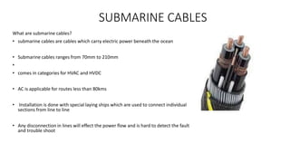
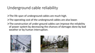
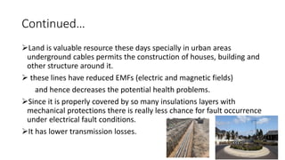
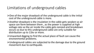
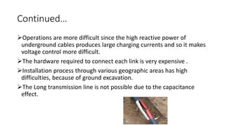
SlideShare a Scribd company logo
UNDERGROUND CABLE IN
TRANSMISSION
Zeeshan Ahmed- s4602680
Naeem ullah- s4586624
Pavan Kumar- s4589278
Jarnil Parmar - s4603457
Nikhil Bhatia- s4597399
Faizan Sabry- s4589813
Akash patel- s4602612
STRUCTURE OF AN
UNDERGROUND CABLE SYSTEM
• The underground lines can outscore the
overhead lines in their appearance.
• But are not completely invisible because
of the protection provided
• Construction of buildings are not allowed
where these lines are installed.
The route of underground cable have many components
• The underground cable itself
• Cable joints
• Transfer station
And if the line is AC
• Power factor correction equipment's
o Reactors (when voltage is high)
o Capacitor banks (when the voltage is low)
Underground cable used as transmission
medium
The main areas of underground cable
are
• Cable sheath
• Wire screen
• Insulating layer
• Conductor
Apart from that it has
• Inner sheath
• Bedding
Insulation media of an underground cable
• Practically insulation made of plastic is used for the underground
cables.
• It has better operating characteristics compared to other types of
insulation and are easy and faster to install it on site.
• The polyethylene(PE) that is used is passed through a
thermochemical process to make it a cross linked polyethylene (XLPE).
• These cables can be used for high temperatures and up to 500kV
voltage level.
• The cables used for DC are similar to the cables used in AC system.
• But have more demands from the side of technology like for jointing
and the insulation used.
• The insulation used in DC cables is Paper insulated, Mass-
impregnated insulation (MI).
• In this the conductor is wrapped around with many layers of paper
and then impregnated with a impregnating material.
• Disadvantage : installing of cable joints are complicated and has to be
sheathed on site.
• But now cables with plastic insulation are being used initially for a
voltage level up to 320kV.
Cable joining
Why cable joints?
• The cables are rounded up on a drum
and then gets transported.
• Trucks are used as means of transportation and have many obstacles
while transporting
Therefore a length of up to 1000 to 1300 meters can only be round up
on a drum.
Hence a cable joint at roughly over a kilometre is used to connect the
cables.
The other main reasons are
• Future installation
• Future repairs
• For making cables easily accessible.
Continued…
Cable transfer station
• The transfer stations are built where the underground cables are put
into ground and again from where they are taken out.
• The size of small substation is very much like this transfer station.
• But in the case of grid which is AC, power factor correction
equipment's are also added and increasing the size of the transfer
station.
Planning of underground cable
Inform
populations of
project intentions
1
Make it
transparent to
public
2
Incorporate
additional
information
3
Develop economy
viable solution
4
New power link
operate safely
5
Planning and environmental issues for
underground cables
• land use and archaeological sites must be assessed
• volume of spoil excavated underground cable is 14 times more than of an
equivalent of the overhead line routes.
• underground joint bays, which are concrete lined and wider than
the trenches themselves have to be built every 500-1000 m.
• Land use restrictions over cable routes.
• Operation, maintenance, refurbishment and up-rating cables
Construction process of underground cables
• Site Preparation
• Duct Bank Installation
• Trenchless Crossings
• Cable Pulling
• Splice Pits / Splice Vaults
• Road Restoration
Site
Preparation
• In the beginning stages of
construction the
underground alignment will
be surveyed and existing
utilities will be demarcated.
Traffic control measures will
be implemented to provide a
safe working area. In areas
where the installation is in a
paved road, the pavement
will be saw cut before
excavation
Trenchless Crossings
• During the process of
installing the conduit
system there are
some cases a
trenchless crossing
technique is utilized,
such as horizontal
directional drilling or
a horizontal bore.
Some typical
applications for these
types of uses are
when crossing under
rivers, streams, large
culverts, highways or
railroads
Cable Pulling
• Once the splice pits or splice vaults are installed, the
cable is pulled through the conduit system from splice
point to splice/termination point. This means that
during cable installation, the only locations that will
have disturbance shall be the splice locations. After the
cable has been pulled into a pit or vault it is spliced to
the next run of cable. Once the splicing operation has
been completed, the splice pit or splice vault is restored
to grade and the splicing operation moves to the next
splice location.
Splice Vaults
• The underground conduit system will terminate at splice pits,
splice vaults or the underground to overhead transition
stations. Pits and vaults are precast concrete structures and
spaced about 1,500 to 2,500 feet apart (the typical length of
a cable segment). Splice pits are filled with a granular
material, a precast lid is placed on top, and the area will be
restored. Once restored, there will be no visible evidence
that a splice pit exists at the installed location. Splice vaults
will not be filled with any granular materials, they will have
riser rings and manhole covers. Once restored, there will be
no visible evidence that a splice vault is installed at the
location other than the manhole lids installed at grade
Road Restoration
• Upon completion of all underground construction work,
the roads will be restored. In general, surface restoration
shall be done to meet or exceed the pre-construction
conditions. Typically, a twelve foot wide section of the
pavement (equivalent to one travel lane) will be milled
and paved during this process. Where construction
occurred in the shoulders of the roads or off road areas,
the surface will be covered in a layer of loam and seed.
Cable carrying AC or DC voltage
• In cable construction the large grid consists of long transmission line,
transformers and switchgear.
• Large structure makes grid design complex.
• In close-mesh every network node acts like as a substation and it’s
connected to several more nodes by overhead lines.
• Nodes called as the substation.
• The high degree of reliability is obtain by using this complex design of
transmission grid.
• In underground AC transmission we require 10 to 20 times more reactive
power than overhead line. Whereas in DC no reactive power is required.
Capacitance of DC
• Capacitance of AC and DC are different.
• In DC cable before transmitting the power the
capacitance must charged for successful
transmission.
• While we transmit the charge first the
capacitance is charged and after that the
currant starts flowing.
• In the figure the side pockets of the pipe are
firstly filled and than the actual currant starts
flowing. Charging of capacitance in DC cable (explained by
water hose analogy)
• The same analogy used to charge capacitance
of AC Cables.
• Due to positive and negative poles every 20
millisecond it starts to flow in the reverse
direction therefor it can’t be fully charged.
• The constant changing of the direction of
flow every 20 milliseconds means that the
capacitance of a long cable cannot be fully
charged.
• If the hose is long and filling time low the
water cannot reach to the other side of hose
that’s why we can’t use this in long
transmission lines.
Charging of capacitance in AC cable
(explained by water hose analogy)
Capacitance of DC
Transmission & Converters
• DC transmission:-
• To transport DC power it need converters to change AC voltage into DC voltage.
• The converters are made of diode, transistors, capacitors and reactors and it’s protected in the
station shed.
• The AC converter, converts DC into AC and it has capability to stabilized and control the grid
voltage.
• Transmitting DC over long distance is very reliable but the only problem is the cost converters.
DC transmission
Between to AC lines there is a long distance DC line with the converters
AC transmission
• AC transmission has reactive power problem and can be overcome by
reactive power compensation(power factor correction) where the reactors
are resembling with large transformers to provide reactive power.
• In AC transmission the between two reactors there are cable jointing in
every ~1 Km.
• Due to resonance phenomena if the length is higher the stability will be
decreased.
• Definition: Resonance occurs when the amplitude of an object's
oscillations are increased by the matching vibrations of another object.
AC transmission
Between to AC lines there is a long distance DC line with the converters
Source:https://study.com/academy/lesson/resonance-definition-transmission-of-waves.html
• The HVDC cables are used to transform around 700MWt with length
capacity of approximately 600Km.Curranty one line is used to connect
Netherlands with Norway(NorNed).
• In future transmission grid industry is trying to add long distance
EHV DC cross country cables but as of now they have zero
experience in that
• Though there are EHV AV cables are fitted in Europe
• For more than 20 years, Cross linked polyethylene cables (XLPE) Extra High
Voltage (EHV) Alternating Current (AC) cables have a proven track record. From
1996 to 2015 alone, globally 4,691 km cables have been installed, of which:
 1,940 km of 220 – 235 kV
 1,073 km of 245 – 345 kV
 1,678 km of 380 – 500 kV
Source:-http://www.europacable.eu/energy/ehvac-cables
Continued…
Transmission distance Type of Transmission
Below 50km Mostly AC transmission
50km to 70km DC transmission
Above 70km Unable to transmit via AC so DC
transmission is used.
• If we use AC transmission that would be less costly and more reliable.
But in long transmission lines DC has low energy losses.
• HVDC is expensive & with increased distance and power it will make the system
more complex.
Source:-https://www.electronicshub.org/high-voltage-dc-transmission-system/
Continued…
Underground transmission lines in Australia
• Its costs 5 or 10 times (in some places even 13 times) compared to
overhead lines.
• Only a small percentage of lines having voltage 66kV and above are
underground.
• In the low voltage category
• Overhead lines – 24500 km
• Underground lines – 156 km
• In 110kV lines – 4.6% (i.e. only 178km out of 3670km is buried)
• The percentage of lines having voltage level of 132,220,330 and
500kV are even lower.
PERCENTAGE OF POWER LINES
UNDERGROUND BY STATE
State NSW Qld SA Tas Vic WA
U.G.% 8.4 4.5 10 6 4 5.5
SUBMARINE CABLES
What are submarine cables?
• submarine cables are cables which carry electric power beneath the ocean
• Submarine cables ranges from 70mm to 210mm
•
• comes in categories for HVAC and HVDC
• AC is applicable for routes less than 80kms
• Installation is done with special laying ships which are used to connect individual
sections from line to line
• Any disconnection in lines will effect the power flow and is hard to detect the fault
and trouble shoot
SUBMARINE CABLE MAP
SUBMARINE CABLE MAP OF AUSTRALIA
TYPES OF FAULTS IN SUBMARINE CABLE
• The fault type can be classified according to the
following five categories:
• low resistance faults( R≤100Ω)
• high resistance faults, with a resistance in the kΩ
range
• intermittent faults-that become active above a
threshold voltage (typically below the cable
operating voltage)
• Interruptions-cut into two
• Sheath faults- where the cable jacket is damaged
DAMAGE DUE TO ANCHORING
DAMAGE DUE TO AGEING
APPLICATION OF FAULT LOCATING METHODS
• TDR(Time Domain Reflectometry) - works only for low resistance faults
and for cable interruptions.
• The Murray bridge method can be used on resistive faults, up to about 10
MΩ.
• Traditional fault location methods like the SIM, MIM, arc reflection and
ICM for faults on high resistance and intermittent faults are limited to
short cable lengths up to a few kilometers.
• Special HV fault location systems are required for the location of
intermittent faults on long and extra-long submarine cables and for this
decay method is used to terminate the fault. METHODS TO LOCATE FAULTS
BASSLINK AUSTRALIA
INTRODUCTION TO BASSLINK
• It was purchased by Keppel infrastructure in 2005
•Bass link HVDC interconnector was one of the worlds longest
submarine cable project until 2005 linking Tasmania to
Australian mainline providing efficient two way power transfer.
•Bass link HVDC interconnects the 230kV Tasmanian
transmission network at George town substation with
500kV Victorian transmission network at LOY YANG
substation
•The total transmission length is 374kms
•The HVDC system has transfer capacity of up to 626MW
from Tasmania to Victoria.to meet Victorian peek load
demand and to protect tasmania from drought constrained
energy shortage.
MAP ROUTE OF BASSLINK
• Consists of LVDC monopole with metallic return scheme of 500MV
DC voltage
• The metallic run is to eliminate environmental impacts and to
remove corrosion,electrolysis effect and emf.
• Bass link control system is one of the most advanced control
systems for HVDC in the world
• Bass link control system operates under safe operating limits
• It consists of automatic control and limitation software
• Temperatures exceeding 43°C on Loy Yang and 33°C in George
town will automatic limit flows through system
• Regulates the flow with respect to the ambient temperature and is
directly proportional to the flow
OPERATIONS
EQUIPMENTS AND TECHNICAL FEATURES
• Equipped with high voltage semiconductor technology, direct light triggered
thyristors(LTT) with over voltage protection
• LTT'S do not need auxilliary energy for protection,as pulse generated at ground is
directly applied to thyristor gate
• An unique valve design is adopted for loy yang and george town converter station
• Each unit includes two valve sections in series and each comprises a series
connection of thyristors valve module also includes heat sink, clamping structure,
snubber circuit, thyristor voltage monitoring printed circuit boards, valve reactors and a
steep grading capacitor
• The snubber circuit consists of series connection in a capacitor and resistor with wire in
water technology for cooling purpose
• The system consists of HVDC cable, LVDC cable(metallic return) and fibre optic
return
• submarine portion of HVDC is built as a 1500mm2 mass impregnated cables, land
sections are 200mm2 and LVDC metallic run is 1400mm2 XLPE cable
• 1-θ three winding converter transformers with rated power of 200MVA have
been designed for both stations with star delta connections inside valve hall
to avoiding lightning surge stresses of the valves caused by direct strokes.
• Reactors are installed to avoid resonance at low order harmonics,limit
transient over currents and to avoid discontinious current operation at
low DC currents
SMOOTHING REACTOR WITH SOUND SHIELD
CONVERTER TRANSFORMER
Underground cable reliability
The life span of underground cables are much high.
The operating cost of the underground cables are also lower.
The construction of under ground cables can improve the reliability
of power system by decreasing the chances of damages done by bad
weather or by human interruption.
Continued…
Land is valuable resource these days specially in urban areas
underground cables permits the construction of houses, building and
other structure around it.
 these lines have reduced EMFs (electric and magnetic fields)
and hence decreases the potential health problems.
Since it is properly covered by so many insulations layers with
mechanical protections there is really less chance for fault occurrence
under electrical fault conditions.
It has lower transmission losses.
One of the major drawback of the underground cable is the initial
cost of the underground cable is more.
Another drawback is the insulation in the cable gets weaken so air
space can form between them , as the power is supplied at high
voltage rate so the air inside the cable gets ionized and breakdown
occurs so due to this underground cable are only suitable for
distribution up to 11kv or more.
Unwanted digging to find the actual place of fault can cause the
environmental problems.
Underground cables are subjected to the damage due to the ground
movement due to earthquake.
Limitations of underground cables
Continued…
Operations are more difficult since the high reactive power of
underground cables produces large charging currents and so it makes
voltage control more difficult.
The hardware required to connect each link is very expensive .
Installation process through various geographic areas has high
difficulties, because of ground excavation.
The Long transmission line is not possible due to the capacitance
effect.
Grid reliability
There are some grid reliability standards which are set and under
which the reliability of current or future grid should be evaluated.
If the failure in one system occurs then also the electricity power
must be available in the system through alterative way without
causing further damage to the system this process is called the N 1
criterion and it shows the maximum reliability of the system.
However the finding the exact location of fault is time consuming
method compare to overhead and repairing work is also complex
method and time taking.
THANK YOU
QUESTIONS ?

More Related Content

What's hot

Types of insulator
Types of insulatorTypes of insulator
Types of insulator
adeelshafiq
 
Sag in overhead transmission line, sag calculation & string chart
Sag in overhead transmission line, sag   calculation & string chartSag in overhead transmission line, sag   calculation & string chart
Sag in overhead transmission line, sag calculation & string chart
vishalgohel12195
 
Power cable - Installation methods
Power cable - Installation methodsPower cable - Installation methods
Power cable - Installation methods
Leonardo ENERGY
 
Chapter 4 mechanical design of transmission lines
Chapter 4  mechanical design of transmission linesChapter 4  mechanical design of transmission lines
Chapter 4 mechanical design of transmission lines
firaoltemesgen1
 
Hv module 3 Impulse voltage generation
Hv module 3 Impulse voltage generationHv module 3 Impulse voltage generation
Hv module 3 Impulse voltage generation
Asha Anu Kurian
 
Lightning arrester
Lightning arresterLightning arrester
Lightning arrester
gajendra singh
 
Underground cables
Underground cablesUnderground cables
Underground cables
Anu71
 
construction of underground cable
construction of underground cableconstruction of underground cable
construction of underground cable
Rajal Patel
 
under ground transmission line
under ground transmission lineunder ground transmission line
under ground transmission line
college
 
Protection of transmission lines(encrypted)
Protection of transmission lines(encrypted)Protection of transmission lines(encrypted)
Protection of transmission lines(encrypted)
Rohini Haridas
 
Underground cables
Underground cablesUnderground cables
Underground cables
Poonam Sarawgi
 
Presentation topic is transmission line
Presentation topic is transmission linePresentation topic is transmission line
Presentation topic is transmission line
md muzahidul haque
 
Overhead line work ppt
Overhead line work pptOverhead line work ppt
Overhead line work ppt
Demsew Mitiku
 
Vacuum circuit breaker
Vacuum circuit breakerVacuum circuit breaker
Vacuum circuit breaker
Harshit Srivastava
 
Structure of power system
Structure of power systemStructure of power system
Structure of power system
Revathi Subramaniam
 
Underground cables vs overhead lines
Underground cables vs overhead linesUnderground cables vs overhead lines
Underground cables vs overhead lines
ସୁର୍ଯ଼ ପ୍ରତାପ ଭଞ୍ଜ
 
Comparison of conductor material
Comparison of conductor materialComparison of conductor material
Comparison of conductor material
vishalgohel12195
 
Protection against overvoltage
Protection against overvoltageProtection against overvoltage
Protection against overvoltage
vishalgohel12195
 
Chapter 3 Generation of high voltages and current
Chapter 3 Generation of high voltages and currentChapter 3 Generation of high voltages and current
Chapter 3 Generation of high voltages and current
mukund mukund.m
 
study of lightning arrester
study of lightning arresterstudy of lightning arrester
study of lightning arrester
Malikasad thaheem
 

What's hot (20)

Types of insulator
Types of insulatorTypes of insulator
Types of insulator
 
Sag in overhead transmission line, sag calculation & string chart
Sag in overhead transmission line, sag   calculation & string chartSag in overhead transmission line, sag   calculation & string chart
Sag in overhead transmission line, sag calculation & string chart
 
Power cable - Installation methods
Power cable - Installation methodsPower cable - Installation methods
Power cable - Installation methods
 
Chapter 4 mechanical design of transmission lines
Chapter 4  mechanical design of transmission linesChapter 4  mechanical design of transmission lines
Chapter 4 mechanical design of transmission lines
 
Hv module 3 Impulse voltage generation
Hv module 3 Impulse voltage generationHv module 3 Impulse voltage generation
Hv module 3 Impulse voltage generation
 
Lightning arrester
Lightning arresterLightning arrester
Lightning arrester
 
Underground cables
Underground cablesUnderground cables
Underground cables
 
construction of underground cable
construction of underground cableconstruction of underground cable
construction of underground cable
 
under ground transmission line
under ground transmission lineunder ground transmission line
under ground transmission line
 
Protection of transmission lines(encrypted)
Protection of transmission lines(encrypted)Protection of transmission lines(encrypted)
Protection of transmission lines(encrypted)
 
Underground cables
Underground cablesUnderground cables
Underground cables
 
Presentation topic is transmission line
Presentation topic is transmission linePresentation topic is transmission line
Presentation topic is transmission line
 
Overhead line work ppt
Overhead line work pptOverhead line work ppt
Overhead line work ppt
 
Vacuum circuit breaker
Vacuum circuit breakerVacuum circuit breaker
Vacuum circuit breaker
 
Structure of power system
Structure of power systemStructure of power system
Structure of power system
 
Underground cables vs overhead lines
Underground cables vs overhead linesUnderground cables vs overhead lines
Underground cables vs overhead lines
 
Comparison of conductor material
Comparison of conductor materialComparison of conductor material
Comparison of conductor material
 
Protection against overvoltage
Protection against overvoltageProtection against overvoltage
Protection against overvoltage
 
Chapter 3 Generation of high voltages and current
Chapter 3 Generation of high voltages and currentChapter 3 Generation of high voltages and current
Chapter 3 Generation of high voltages and current
 
study of lightning arrester
study of lightning arresterstudy of lightning arrester
study of lightning arrester
 

Similar to underground cable in transmission grid

Supply system (Electrical Power System)
Supply system (Electrical Power System)Supply system (Electrical Power System)
Supply system (Electrical Power System)
Abhishek Choksi
 
Comparison of AC and DC.pptx
Comparison of AC and DC.pptxComparison of AC and DC.pptx
Comparison of AC and DC.pptx
RenukaKutte
 
Residential Electrical Equipments and Services.pptx
Residential Electrical Equipments and Services.pptxResidential Electrical Equipments and Services.pptx
Residential Electrical Equipments and Services.pptx
Deepti Shitoley
 
Ehv substation
Ehv substationEhv substation
Ehv substation
Demsew Mitiku
 
HVDC presentation
HVDC presentationHVDC presentation
HVDC presentation
sagnikroychowdhury
 
3.chapter 1 ohtl vs cables
3.chapter 1 ohtl vs cables3.chapter 1 ohtl vs cables
3.chapter 1 ohtl vs cables
ssuser30d0c22
 
Presentation: AC Mitigation Case Histories
Presentation: AC Mitigation Case HistoriesPresentation: AC Mitigation Case Histories
Presentation: AC Mitigation Case Histories
Marcellus Drilling News
 
A Training Report Of Saltlake 132/33kv Substation
A Training Report Of Saltlake 132/33kv SubstationA Training Report Of Saltlake 132/33kv Substation
A Training Report Of Saltlake 132/33kv Substation
Subhrajit Ghosh
 
Construction of HV Transmission Lines etc.pptx
Construction of HV Transmission Lines etc.pptxConstruction of HV Transmission Lines etc.pptx
Construction of HV Transmission Lines etc.pptx
Satish Pydimarla
 
Laying of Underground Cables in INSTALLATION AND MAINTENANCE OF ELECTRICAL EQ...
Laying of Underground Cables in INSTALLATION AND MAINTENANCE OF ELECTRICAL EQ...Laying of Underground Cables in INSTALLATION AND MAINTENANCE OF ELECTRICAL EQ...
Laying of Underground Cables in INSTALLATION AND MAINTENANCE OF ELECTRICAL EQ...
AkankshaSharma570781
 
Laying of Underground Cables.pptx
Laying of Underground Cables.pptxLaying of Underground Cables.pptx
Laying of Underground Cables.pptx
DrAkankshaSharma4
 
TDU - Unit 01 Transmission system
TDU - Unit  01 Transmission system TDU - Unit  01 Transmission system
TDU - Unit 01 Transmission system
PremanandDesai
 
Mankotia ankit
Mankotia ankitMankotia ankit
Mankotia ankit
Thakur Mankotia
 
final document epgt train overhead sytem
final document epgt train overhead sytemfinal document epgt train overhead sytem
final document epgt train overhead sytem
darshanarkasali2
 
Transmission and Distribution - Line parameters.pptx
Transmission and Distribution - Line parameters.pptxTransmission and Distribution - Line parameters.pptx
Transmission and Distribution - Line parameters.pptx
karthik prabhu
 
132 k v-substation-training-for-students
132 k v-substation-training-for-students132 k v-substation-training-for-students
132 k v-substation-training-for-students
Sanjay Kumar Sharma
 
Power System electrical and electronics .pptx
Power System electrical and electronics .pptxPower System electrical and electronics .pptx
Power System electrical and electronics .pptx
MUKULKUMAR210
 
Supplier Hoist Cranes Jakarta | stahlindo
Supplier Hoist Cranes Jakarta | stahlindoSupplier Hoist Cranes Jakarta | stahlindo
Supplier Hoist Cranes Jakarta | stahlindo
Stahlindo Indonesia
 
PPT_1_Electrical services_By group no. 1.pptx
PPT_1_Electrical services_By group no. 1.pptxPPT_1_Electrical services_By group no. 1.pptx
PPT_1_Electrical services_By group no. 1.pptx
ayazkhan261
 
PPT_1_Electrical services_By group no. 1.pptx
PPT_1_Electrical services_By group no. 1.pptxPPT_1_Electrical services_By group no. 1.pptx
PPT_1_Electrical services_By group no. 1.pptx
ayazkhan261
 

Similar to underground cable in transmission grid (20)

Supply system (Electrical Power System)
Supply system (Electrical Power System)Supply system (Electrical Power System)
Supply system (Electrical Power System)
 
Comparison of AC and DC.pptx
Comparison of AC and DC.pptxComparison of AC and DC.pptx
Comparison of AC and DC.pptx
 
Residential Electrical Equipments and Services.pptx
Residential Electrical Equipments and Services.pptxResidential Electrical Equipments and Services.pptx
Residential Electrical Equipments and Services.pptx
 
Ehv substation
Ehv substationEhv substation
Ehv substation
 
HVDC presentation
HVDC presentationHVDC presentation
HVDC presentation
 
3.chapter 1 ohtl vs cables
3.chapter 1 ohtl vs cables3.chapter 1 ohtl vs cables
3.chapter 1 ohtl vs cables
 
Presentation: AC Mitigation Case Histories
Presentation: AC Mitigation Case HistoriesPresentation: AC Mitigation Case Histories
Presentation: AC Mitigation Case Histories
 
A Training Report Of Saltlake 132/33kv Substation
A Training Report Of Saltlake 132/33kv SubstationA Training Report Of Saltlake 132/33kv Substation
A Training Report Of Saltlake 132/33kv Substation
 
Construction of HV Transmission Lines etc.pptx
Construction of HV Transmission Lines etc.pptxConstruction of HV Transmission Lines etc.pptx
Construction of HV Transmission Lines etc.pptx
 
Laying of Underground Cables in INSTALLATION AND MAINTENANCE OF ELECTRICAL EQ...
Laying of Underground Cables in INSTALLATION AND MAINTENANCE OF ELECTRICAL EQ...Laying of Underground Cables in INSTALLATION AND MAINTENANCE OF ELECTRICAL EQ...
Laying of Underground Cables in INSTALLATION AND MAINTENANCE OF ELECTRICAL EQ...
 
Laying of Underground Cables.pptx
Laying of Underground Cables.pptxLaying of Underground Cables.pptx
Laying of Underground Cables.pptx
 
TDU - Unit 01 Transmission system
TDU - Unit  01 Transmission system TDU - Unit  01 Transmission system
TDU - Unit 01 Transmission system
 
Mankotia ankit
Mankotia ankitMankotia ankit
Mankotia ankit
 
final document epgt train overhead sytem
final document epgt train overhead sytemfinal document epgt train overhead sytem
final document epgt train overhead sytem
 
Transmission and Distribution - Line parameters.pptx
Transmission and Distribution - Line parameters.pptxTransmission and Distribution - Line parameters.pptx
Transmission and Distribution - Line parameters.pptx
 
132 k v-substation-training-for-students
132 k v-substation-training-for-students132 k v-substation-training-for-students
132 k v-substation-training-for-students
 
Power System electrical and electronics .pptx
Power System electrical and electronics .pptxPower System electrical and electronics .pptx
Power System electrical and electronics .pptx
 
Supplier Hoist Cranes Jakarta | stahlindo
Supplier Hoist Cranes Jakarta | stahlindoSupplier Hoist Cranes Jakarta | stahlindo
Supplier Hoist Cranes Jakarta | stahlindo
 
PPT_1_Electrical services_By group no. 1.pptx
PPT_1_Electrical services_By group no. 1.pptxPPT_1_Electrical services_By group no. 1.pptx
PPT_1_Electrical services_By group no. 1.pptx
 
PPT_1_Electrical services_By group no. 1.pptx
PPT_1_Electrical services_By group no. 1.pptxPPT_1_Electrical services_By group no. 1.pptx
PPT_1_Electrical services_By group no. 1.pptx
 

Recently uploaded

Software Engineering and Project Management - Introduction, Modeling Concepts...
Software Engineering and Project Management - Introduction, Modeling Concepts...Software Engineering and Project Management - Introduction, Modeling Concepts...
Software Engineering and Project Management - Introduction, Modeling Concepts...
Prakhyath Rai
 
The Python for beginners. This is an advance computer language.
The Python for beginners. This is an advance computer language.The Python for beginners. This is an advance computer language.
The Python for beginners. This is an advance computer language.
sachin chaurasia
 
哪里办理(csu毕业证书)查尔斯特大学毕业证硕士学历原版一模一样
哪里办理(csu毕业证书)查尔斯特大学毕业证硕士学历原版一模一样哪里办理(csu毕业证书)查尔斯特大学毕业证硕士学历原版一模一样
哪里办理(csu毕业证书)查尔斯特大学毕业证硕士学历原版一模一样
insn4465
 
Engineering Drawings Lecture Detail Drawings 2014.pdf
Engineering Drawings Lecture Detail Drawings 2014.pdfEngineering Drawings Lecture Detail Drawings 2014.pdf
Engineering Drawings Lecture Detail Drawings 2014.pdf
abbyasa1014
 
Mechanical Engineering on AAI Summer Training Report-003.pdf
Mechanical Engineering on AAI Summer Training Report-003.pdfMechanical Engineering on AAI Summer Training Report-003.pdf
Mechanical Engineering on AAI Summer Training Report-003.pdf
21UME003TUSHARDEB
 
Transformers design and coooling methods
Transformers design and coooling methodsTransformers design and coooling methods
Transformers design and coooling methods
Roger Rozario
 
Embedded machine learning-based road conditions and driving behavior monitoring
Embedded machine learning-based road conditions and driving behavior monitoringEmbedded machine learning-based road conditions and driving behavior monitoring
Embedded machine learning-based road conditions and driving behavior monitoring
IJECEIAES
 
Manufacturing Process of molasses based distillery ppt.pptx
Manufacturing Process of molasses based distillery ppt.pptxManufacturing Process of molasses based distillery ppt.pptx
Manufacturing Process of molasses based distillery ppt.pptx
Madan Karki
 
Certificates - Mahmoud Mohamed Moursi Ahmed
Certificates - Mahmoud Mohamed Moursi AhmedCertificates - Mahmoud Mohamed Moursi Ahmed
Certificates - Mahmoud Mohamed Moursi Ahmed
Mahmoud Morsy
 
Seminar on Distillation study-mafia.pptx
Seminar on Distillation study-mafia.pptxSeminar on Distillation study-mafia.pptx
Seminar on Distillation study-mafia.pptx
Madan Karki
 
LLM Fine Tuning with QLoRA Cassandra Lunch 4, presented by Anant
LLM Fine Tuning with QLoRA Cassandra Lunch 4, presented by AnantLLM Fine Tuning with QLoRA Cassandra Lunch 4, presented by Anant
LLM Fine Tuning with QLoRA Cassandra Lunch 4, presented by Anant
Anant Corporation
 
学校原版美国波士顿大学毕业证学历学位证书原版一模一样
学校原版美国波士顿大学毕业证学历学位证书原版一模一样学校原版美国波士顿大学毕业证学历学位证书原版一模一样
学校原版美国波士顿大学毕业证学历学位证书原版一模一样
171ticu
 
International Conference on NLP, Artificial Intelligence, Machine Learning an...
International Conference on NLP, Artificial Intelligence, Machine Learning an...International Conference on NLP, Artificial Intelligence, Machine Learning an...
International Conference on NLP, Artificial Intelligence, Machine Learning an...
gerogepatton
 
Material for memory and display system h
Material for memory and display system hMaterial for memory and display system h
Material for memory and display system h
gowrishankartb2005
 
ISPM 15 Heat Treated Wood Stamps and why your shipping must have one
ISPM 15 Heat Treated Wood Stamps and why your shipping must have oneISPM 15 Heat Treated Wood Stamps and why your shipping must have one
ISPM 15 Heat Treated Wood Stamps and why your shipping must have one
Las Vegas Warehouse
 
Hematology Analyzer Machine - Complete Blood Count
Hematology Analyzer Machine - Complete Blood CountHematology Analyzer Machine - Complete Blood Count
Hematology Analyzer Machine - Complete Blood Count
shahdabdulbaset
 
Curve Fitting in Numerical Methods Regression
Curve Fitting in Numerical Methods RegressionCurve Fitting in Numerical Methods Regression
Curve Fitting in Numerical Methods Regression
Nada Hikmah
 
Electric vehicle and photovoltaic advanced roles in enhancing the financial p...
Electric vehicle and photovoltaic advanced roles in enhancing the financial p...Electric vehicle and photovoltaic advanced roles in enhancing the financial p...
Electric vehicle and photovoltaic advanced roles in enhancing the financial p...
IJECEIAES
 
IEEE Aerospace and Electronic Systems Society as a Graduate Student Member
IEEE Aerospace and Electronic Systems Society as a Graduate Student MemberIEEE Aerospace and Electronic Systems Society as a Graduate Student Member
IEEE Aerospace and Electronic Systems Society as a Graduate Student Member
VICTOR MAESTRE RAMIREZ
 
Null Bangalore | Pentesters Approach to AWS IAM
Null Bangalore | Pentesters Approach to AWS IAMNull Bangalore | Pentesters Approach to AWS IAM
Null Bangalore | Pentesters Approach to AWS IAM
Divyanshu
 

Recently uploaded (20)

Software Engineering and Project Management - Introduction, Modeling Concepts...
Software Engineering and Project Management - Introduction, Modeling Concepts...Software Engineering and Project Management - Introduction, Modeling Concepts...
Software Engineering and Project Management - Introduction, Modeling Concepts...
 
The Python for beginners. This is an advance computer language.
The Python for beginners. This is an advance computer language.The Python for beginners. This is an advance computer language.
The Python for beginners. This is an advance computer language.
 
哪里办理(csu毕业证书)查尔斯特大学毕业证硕士学历原版一模一样
哪里办理(csu毕业证书)查尔斯特大学毕业证硕士学历原版一模一样哪里办理(csu毕业证书)查尔斯特大学毕业证硕士学历原版一模一样
哪里办理(csu毕业证书)查尔斯特大学毕业证硕士学历原版一模一样
 
Engineering Drawings Lecture Detail Drawings 2014.pdf
Engineering Drawings Lecture Detail Drawings 2014.pdfEngineering Drawings Lecture Detail Drawings 2014.pdf
Engineering Drawings Lecture Detail Drawings 2014.pdf
 
Mechanical Engineering on AAI Summer Training Report-003.pdf
Mechanical Engineering on AAI Summer Training Report-003.pdfMechanical Engineering on AAI Summer Training Report-003.pdf
Mechanical Engineering on AAI Summer Training Report-003.pdf
 
Transformers design and coooling methods
Transformers design and coooling methodsTransformers design and coooling methods
Transformers design and coooling methods
 
Embedded machine learning-based road conditions and driving behavior monitoring
Embedded machine learning-based road conditions and driving behavior monitoringEmbedded machine learning-based road conditions and driving behavior monitoring
Embedded machine learning-based road conditions and driving behavior monitoring
 
Manufacturing Process of molasses based distillery ppt.pptx
Manufacturing Process of molasses based distillery ppt.pptxManufacturing Process of molasses based distillery ppt.pptx
Manufacturing Process of molasses based distillery ppt.pptx
 
Certificates - Mahmoud Mohamed Moursi Ahmed
Certificates - Mahmoud Mohamed Moursi AhmedCertificates - Mahmoud Mohamed Moursi Ahmed
Certificates - Mahmoud Mohamed Moursi Ahmed
 
Seminar on Distillation study-mafia.pptx
Seminar on Distillation study-mafia.pptxSeminar on Distillation study-mafia.pptx
Seminar on Distillation study-mafia.pptx
 
LLM Fine Tuning with QLoRA Cassandra Lunch 4, presented by Anant
LLM Fine Tuning with QLoRA Cassandra Lunch 4, presented by AnantLLM Fine Tuning with QLoRA Cassandra Lunch 4, presented by Anant
LLM Fine Tuning with QLoRA Cassandra Lunch 4, presented by Anant
 
学校原版美国波士顿大学毕业证学历学位证书原版一模一样
学校原版美国波士顿大学毕业证学历学位证书原版一模一样学校原版美国波士顿大学毕业证学历学位证书原版一模一样
学校原版美国波士顿大学毕业证学历学位证书原版一模一样
 
International Conference on NLP, Artificial Intelligence, Machine Learning an...
International Conference on NLP, Artificial Intelligence, Machine Learning an...International Conference on NLP, Artificial Intelligence, Machine Learning an...
International Conference on NLP, Artificial Intelligence, Machine Learning an...
 
Material for memory and display system h
Material for memory and display system hMaterial for memory and display system h
Material for memory and display system h
 
ISPM 15 Heat Treated Wood Stamps and why your shipping must have one
ISPM 15 Heat Treated Wood Stamps and why your shipping must have oneISPM 15 Heat Treated Wood Stamps and why your shipping must have one
ISPM 15 Heat Treated Wood Stamps and why your shipping must have one
 
Hematology Analyzer Machine - Complete Blood Count
Hematology Analyzer Machine - Complete Blood CountHematology Analyzer Machine - Complete Blood Count
Hematology Analyzer Machine - Complete Blood Count
 
Curve Fitting in Numerical Methods Regression
Curve Fitting in Numerical Methods RegressionCurve Fitting in Numerical Methods Regression
Curve Fitting in Numerical Methods Regression
 
Electric vehicle and photovoltaic advanced roles in enhancing the financial p...
Electric vehicle and photovoltaic advanced roles in enhancing the financial p...Electric vehicle and photovoltaic advanced roles in enhancing the financial p...
Electric vehicle and photovoltaic advanced roles in enhancing the financial p...
 
IEEE Aerospace and Electronic Systems Society as a Graduate Student Member
IEEE Aerospace and Electronic Systems Society as a Graduate Student MemberIEEE Aerospace and Electronic Systems Society as a Graduate Student Member
IEEE Aerospace and Electronic Systems Society as a Graduate Student Member
 
Null Bangalore | Pentesters Approach to AWS IAM
Null Bangalore | Pentesters Approach to AWS IAMNull Bangalore | Pentesters Approach to AWS IAM
Null Bangalore | Pentesters Approach to AWS IAM
 

underground cable in transmission grid

  • 1. UNDERGROUND CABLE IN TRANSMISSION Zeeshan Ahmed- s4602680 Naeem ullah- s4586624 Pavan Kumar- s4589278 Jarnil Parmar - s4603457 Nikhil Bhatia- s4597399 Faizan Sabry- s4589813 Akash patel- s4602612
  • 2. STRUCTURE OF AN UNDERGROUND CABLE SYSTEM • The underground lines can outscore the overhead lines in their appearance. • But are not completely invisible because of the protection provided • Construction of buildings are not allowed where these lines are installed.
  • 3. The route of underground cable have many components • The underground cable itself • Cable joints • Transfer station And if the line is AC • Power factor correction equipment's o Reactors (when voltage is high) o Capacitor banks (when the voltage is low)
  • 4. Underground cable used as transmission medium The main areas of underground cable are • Cable sheath • Wire screen • Insulating layer • Conductor Apart from that it has • Inner sheath • Bedding
  • 5. Insulation media of an underground cable • Practically insulation made of plastic is used for the underground cables. • It has better operating characteristics compared to other types of insulation and are easy and faster to install it on site. • The polyethylene(PE) that is used is passed through a thermochemical process to make it a cross linked polyethylene (XLPE). • These cables can be used for high temperatures and up to 500kV voltage level.
  • 6. • The cables used for DC are similar to the cables used in AC system. • But have more demands from the side of technology like for jointing and the insulation used. • The insulation used in DC cables is Paper insulated, Mass- impregnated insulation (MI). • In this the conductor is wrapped around with many layers of paper and then impregnated with a impregnating material. • Disadvantage : installing of cable joints are complicated and has to be sheathed on site. • But now cables with plastic insulation are being used initially for a voltage level up to 320kV.
  • 8. • The cables are rounded up on a drum and then gets transported. • Trucks are used as means of transportation and have many obstacles while transporting
  • 9. Therefore a length of up to 1000 to 1300 meters can only be round up on a drum. Hence a cable joint at roughly over a kilometre is used to connect the cables. The other main reasons are • Future installation • Future repairs • For making cables easily accessible. Continued…
  • 10. Cable transfer station • The transfer stations are built where the underground cables are put into ground and again from where they are taken out. • The size of small substation is very much like this transfer station. • But in the case of grid which is AC, power factor correction equipment's are also added and increasing the size of the transfer station.
  • 11. Planning of underground cable Inform populations of project intentions 1 Make it transparent to public 2 Incorporate additional information 3 Develop economy viable solution 4 New power link operate safely 5
  • 12. Planning and environmental issues for underground cables • land use and archaeological sites must be assessed • volume of spoil excavated underground cable is 14 times more than of an equivalent of the overhead line routes. • underground joint bays, which are concrete lined and wider than the trenches themselves have to be built every 500-1000 m. • Land use restrictions over cable routes. • Operation, maintenance, refurbishment and up-rating cables
  • 13. Construction process of underground cables • Site Preparation • Duct Bank Installation • Trenchless Crossings • Cable Pulling • Splice Pits / Splice Vaults • Road Restoration
  • 14. Site Preparation • In the beginning stages of construction the underground alignment will be surveyed and existing utilities will be demarcated. Traffic control measures will be implemented to provide a safe working area. In areas where the installation is in a paved road, the pavement will be saw cut before excavation
  • 15. Trenchless Crossings • During the process of installing the conduit system there are some cases a trenchless crossing technique is utilized, such as horizontal directional drilling or a horizontal bore. Some typical applications for these types of uses are when crossing under rivers, streams, large culverts, highways or railroads
  • 16. Cable Pulling • Once the splice pits or splice vaults are installed, the cable is pulled through the conduit system from splice point to splice/termination point. This means that during cable installation, the only locations that will have disturbance shall be the splice locations. After the cable has been pulled into a pit or vault it is spliced to the next run of cable. Once the splicing operation has been completed, the splice pit or splice vault is restored to grade and the splicing operation moves to the next splice location.
  • 17. Splice Vaults • The underground conduit system will terminate at splice pits, splice vaults or the underground to overhead transition stations. Pits and vaults are precast concrete structures and spaced about 1,500 to 2,500 feet apart (the typical length of a cable segment). Splice pits are filled with a granular material, a precast lid is placed on top, and the area will be restored. Once restored, there will be no visible evidence that a splice pit exists at the installed location. Splice vaults will not be filled with any granular materials, they will have riser rings and manhole covers. Once restored, there will be no visible evidence that a splice vault is installed at the location other than the manhole lids installed at grade
  • 18. Road Restoration • Upon completion of all underground construction work, the roads will be restored. In general, surface restoration shall be done to meet or exceed the pre-construction conditions. Typically, a twelve foot wide section of the pavement (equivalent to one travel lane) will be milled and paved during this process. Where construction occurred in the shoulders of the roads or off road areas, the surface will be covered in a layer of loam and seed.
  • 19. Cable carrying AC or DC voltage • In cable construction the large grid consists of long transmission line, transformers and switchgear. • Large structure makes grid design complex. • In close-mesh every network node acts like as a substation and it’s connected to several more nodes by overhead lines. • Nodes called as the substation. • The high degree of reliability is obtain by using this complex design of transmission grid. • In underground AC transmission we require 10 to 20 times more reactive power than overhead line. Whereas in DC no reactive power is required.
  • 20. Capacitance of DC • Capacitance of AC and DC are different. • In DC cable before transmitting the power the capacitance must charged for successful transmission. • While we transmit the charge first the capacitance is charged and after that the currant starts flowing. • In the figure the side pockets of the pipe are firstly filled and than the actual currant starts flowing. Charging of capacitance in DC cable (explained by water hose analogy)
  • 21. • The same analogy used to charge capacitance of AC Cables. • Due to positive and negative poles every 20 millisecond it starts to flow in the reverse direction therefor it can’t be fully charged. • The constant changing of the direction of flow every 20 milliseconds means that the capacitance of a long cable cannot be fully charged. • If the hose is long and filling time low the water cannot reach to the other side of hose that’s why we can’t use this in long transmission lines. Charging of capacitance in AC cable (explained by water hose analogy) Capacitance of DC
  • 22. Transmission & Converters • DC transmission:- • To transport DC power it need converters to change AC voltage into DC voltage. • The converters are made of diode, transistors, capacitors and reactors and it’s protected in the station shed. • The AC converter, converts DC into AC and it has capability to stabilized and control the grid voltage. • Transmitting DC over long distance is very reliable but the only problem is the cost converters. DC transmission Between to AC lines there is a long distance DC line with the converters
  • 23. AC transmission • AC transmission has reactive power problem and can be overcome by reactive power compensation(power factor correction) where the reactors are resembling with large transformers to provide reactive power. • In AC transmission the between two reactors there are cable jointing in every ~1 Km. • Due to resonance phenomena if the length is higher the stability will be decreased. • Definition: Resonance occurs when the amplitude of an object's oscillations are increased by the matching vibrations of another object. AC transmission Between to AC lines there is a long distance DC line with the converters Source:https://study.com/academy/lesson/resonance-definition-transmission-of-waves.html
  • 24. • The HVDC cables are used to transform around 700MWt with length capacity of approximately 600Km.Curranty one line is used to connect Netherlands with Norway(NorNed). • In future transmission grid industry is trying to add long distance EHV DC cross country cables but as of now they have zero experience in that • Though there are EHV AV cables are fitted in Europe • For more than 20 years, Cross linked polyethylene cables (XLPE) Extra High Voltage (EHV) Alternating Current (AC) cables have a proven track record. From 1996 to 2015 alone, globally 4,691 km cables have been installed, of which:  1,940 km of 220 – 235 kV  1,073 km of 245 – 345 kV  1,678 km of 380 – 500 kV Source:-http://www.europacable.eu/energy/ehvac-cables Continued…
  • 25. Transmission distance Type of Transmission Below 50km Mostly AC transmission 50km to 70km DC transmission Above 70km Unable to transmit via AC so DC transmission is used. • If we use AC transmission that would be less costly and more reliable. But in long transmission lines DC has low energy losses. • HVDC is expensive & with increased distance and power it will make the system more complex. Source:-https://www.electronicshub.org/high-voltage-dc-transmission-system/ Continued…
  • 26. Underground transmission lines in Australia • Its costs 5 or 10 times (in some places even 13 times) compared to overhead lines. • Only a small percentage of lines having voltage 66kV and above are underground. • In the low voltage category • Overhead lines – 24500 km • Underground lines – 156 km • In 110kV lines – 4.6% (i.e. only 178km out of 3670km is buried) • The percentage of lines having voltage level of 132,220,330 and 500kV are even lower.
  • 27. PERCENTAGE OF POWER LINES UNDERGROUND BY STATE State NSW Qld SA Tas Vic WA U.G.% 8.4 4.5 10 6 4 5.5
  • 28. SUBMARINE CABLES What are submarine cables? • submarine cables are cables which carry electric power beneath the ocean • Submarine cables ranges from 70mm to 210mm • • comes in categories for HVAC and HVDC • AC is applicable for routes less than 80kms • Installation is done with special laying ships which are used to connect individual sections from line to line • Any disconnection in lines will effect the power flow and is hard to detect the fault and trouble shoot
  • 29. SUBMARINE CABLE MAP SUBMARINE CABLE MAP OF AUSTRALIA
  • 30. TYPES OF FAULTS IN SUBMARINE CABLE • The fault type can be classified according to the following five categories: • low resistance faults( R≤100Ω) • high resistance faults, with a resistance in the kΩ range • intermittent faults-that become active above a threshold voltage (typically below the cable operating voltage) • Interruptions-cut into two • Sheath faults- where the cable jacket is damaged DAMAGE DUE TO ANCHORING DAMAGE DUE TO AGEING
  • 31. APPLICATION OF FAULT LOCATING METHODS • TDR(Time Domain Reflectometry) - works only for low resistance faults and for cable interruptions. • The Murray bridge method can be used on resistive faults, up to about 10 MΩ. • Traditional fault location methods like the SIM, MIM, arc reflection and ICM for faults on high resistance and intermittent faults are limited to short cable lengths up to a few kilometers. • Special HV fault location systems are required for the location of intermittent faults on long and extra-long submarine cables and for this decay method is used to terminate the fault. METHODS TO LOCATE FAULTS
  • 32. BASSLINK AUSTRALIA INTRODUCTION TO BASSLINK • It was purchased by Keppel infrastructure in 2005 •Bass link HVDC interconnector was one of the worlds longest submarine cable project until 2005 linking Tasmania to Australian mainline providing efficient two way power transfer. •Bass link HVDC interconnects the 230kV Tasmanian transmission network at George town substation with 500kV Victorian transmission network at LOY YANG substation •The total transmission length is 374kms •The HVDC system has transfer capacity of up to 626MW from Tasmania to Victoria.to meet Victorian peek load demand and to protect tasmania from drought constrained energy shortage. MAP ROUTE OF BASSLINK
  • 33. • Consists of LVDC monopole with metallic return scheme of 500MV DC voltage • The metallic run is to eliminate environmental impacts and to remove corrosion,electrolysis effect and emf. • Bass link control system is one of the most advanced control systems for HVDC in the world • Bass link control system operates under safe operating limits • It consists of automatic control and limitation software • Temperatures exceeding 43°C on Loy Yang and 33°C in George town will automatic limit flows through system • Regulates the flow with respect to the ambient temperature and is directly proportional to the flow OPERATIONS
  • 34. EQUIPMENTS AND TECHNICAL FEATURES • Equipped with high voltage semiconductor technology, direct light triggered thyristors(LTT) with over voltage protection • LTT'S do not need auxilliary energy for protection,as pulse generated at ground is directly applied to thyristor gate • An unique valve design is adopted for loy yang and george town converter station • Each unit includes two valve sections in series and each comprises a series connection of thyristors valve module also includes heat sink, clamping structure, snubber circuit, thyristor voltage monitoring printed circuit boards, valve reactors and a steep grading capacitor • The snubber circuit consists of series connection in a capacitor and resistor with wire in water technology for cooling purpose
  • 35. • The system consists of HVDC cable, LVDC cable(metallic return) and fibre optic return • submarine portion of HVDC is built as a 1500mm2 mass impregnated cables, land sections are 200mm2 and LVDC metallic run is 1400mm2 XLPE cable • 1-θ three winding converter transformers with rated power of 200MVA have been designed for both stations with star delta connections inside valve hall to avoiding lightning surge stresses of the valves caused by direct strokes. • Reactors are installed to avoid resonance at low order harmonics,limit transient over currents and to avoid discontinious current operation at low DC currents SMOOTHING REACTOR WITH SOUND SHIELD CONVERTER TRANSFORMER
  • 36. Underground cable reliability The life span of underground cables are much high. The operating cost of the underground cables are also lower. The construction of under ground cables can improve the reliability of power system by decreasing the chances of damages done by bad weather or by human interruption.
  • 37. Continued… Land is valuable resource these days specially in urban areas underground cables permits the construction of houses, building and other structure around it.  these lines have reduced EMFs (electric and magnetic fields) and hence decreases the potential health problems. Since it is properly covered by so many insulations layers with mechanical protections there is really less chance for fault occurrence under electrical fault conditions. It has lower transmission losses.
  • 38. One of the major drawback of the underground cable is the initial cost of the underground cable is more. Another drawback is the insulation in the cable gets weaken so air space can form between them , as the power is supplied at high voltage rate so the air inside the cable gets ionized and breakdown occurs so due to this underground cable are only suitable for distribution up to 11kv or more. Unwanted digging to find the actual place of fault can cause the environmental problems. Underground cables are subjected to the damage due to the ground movement due to earthquake. Limitations of underground cables
  • 39. Continued… Operations are more difficult since the high reactive power of underground cables produces large charging currents and so it makes voltage control more difficult. The hardware required to connect each link is very expensive . Installation process through various geographic areas has high difficulties, because of ground excavation. The Long transmission line is not possible due to the capacitance effect.
  • 40. Grid reliability There are some grid reliability standards which are set and under which the reliability of current or future grid should be evaluated. If the failure in one system occurs then also the electricity power must be available in the system through alterative way without causing further damage to the system this process is called the N 1 criterion and it shows the maximum reliability of the system. However the finding the exact location of fault is time consuming method compare to overhead and repairing work is also complex method and time taking.