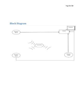
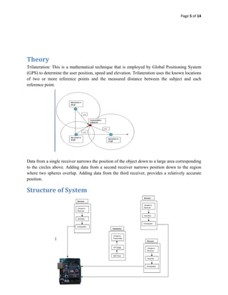
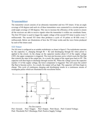
This project developed an ultrasonic positioning system that uses trilateration to determine the position of an ultrasonic transmitter based on the time delays of signals received by three receivers. The system includes a transmitter that pulses ultrasonic signals every 5 milliseconds, receivers that amplify and convert received signals, and an Arduino that calculates the position using time differences between received pulses and displays the x,y coordinates. Some challenges encountered were accurately recording pulse transmission and receipt times and dealing with noise interference.
The document discusses principles of radar imaging and synthetic aperture radar (SAR). SAR uses signal modulation and range-Doppler processing to achieve high-resolution radar imagery independent of distance to targets. Polarimetric SAR can characterize target scattering properties by measuring the scattering matrix. Interferometric SAR uses two antennas to measure elevation, while differential interferometry detects elevation changes over time for applications like change detection. Emerging techniques include polarimetric interferometry and using polarization signatures to estimate surface tilt and topography.
This document discusses NI's AWR Design Environment software platform for radar design. It provides fully integrated design, simulation, and testing capabilities for microwave, RF, and radar systems. Key features include circuit design tools, 3D electromagnetic simulation, and the Visual System Simulator for behavioral modeling of radar signal processing and systems. The software allows for co-simulation of digital and analog sections and supports common programming languages. It has applications in weather radar, phased arrays, and other radar systems. The document provides an overview of the company and software capabilities.
Radar Systems- Unit-III : MTI and Pulse Doppler RadarsVenkataRatnam14
This document provides an overview of moving target indication (MTI) and pulse Doppler radar systems. It describes the basic principles of MTI radar, including using Doppler shift to distinguish moving targets from clutter. It discusses different types of MTI radars and delay line cancellers. It also covers topics like blind speeds, staggered PRFs, range gated Doppler filters, and limitations to MTI performance. The key difference between MTI and pulse Doppler radar mentioned is that MTI radar operates with ambiguous Doppler but unambiguous range, while pulse Doppler radar has ambiguous range but unambiguous Doppler.
This document discusses continuous wave (CW) radar and frequency modulated continuous wave (FMCW) radar. It defines radar as an electromagnetic device that can detect objects hidden from view using radio waves. Radar is classified into primary types including CW and modulated radar. CW radar uses the Doppler effect to detect moving targets based on changes in transmitted frequency. However, CW radar cannot determine range. FMCW radar modulates the transmitted frequency over time and compares the received frequency to determine both range and radial velocity of targets. Key applications of radar include military surveillance, weather monitoring, air traffic control and more.
An AM transmitter with an effective carrier power of 50KW is being analyzed. For a modulation index of 50%:
1) The total effective power is 75KW.
2) The effective power in each sideband is 12.5KW.
For 100% modulation:
3) The total effective power is 75KW.
4) The effective power in each sideband is 25KW.
This document provides an overview of the course content for Unit 1 of a radar systems course. The key topics covered include the modified radar range equation, signal-to-noise ratio, probability of detection and false alarms, integration of radar pulses, radar cross section of targets, creeping waves, transmitter power, pulse repetition frequency and range ambiguities, and system losses. The document also provides qualitative explanations and equations for several radar concepts.
ALTITUDE. Vertical distance of an aircraft or object above a given reference, such as ground or sea level.
AMPLIFIER. An electronic device used to increase signal magnitude or power.
AMPLITUDE MODULATION (AM). A method of impressing a message upon a carrier signal by causing the carrier amplitude to vary proportionally to the message waveform.
ANTENNA SYSTEM. Routes RF energy from the transmitter, radiates the energy into space, receives echoes, and routes the echoes to the receiver.
A presentation prepared by my friend's friend. I have done no editing at all, I'm just uploading the presentation as it is.
The document discusses radar clutter and techniques for eliminating it. Clutter refers to radar returns from stationary objects that are not of interest. Two main techniques for reducing clutter are discussed: moving target indication (MTI) radar, which detects Doppler shifts from moving targets, and delay line cancellers/transversal filters, which cancel out stationary clutter returns. MTI radars preserve phase coherence to differentiate stationary vs moving targets, while cancellers/filters use weighted signal delays and summing to attenuate clutter signals.
The document discusses digital signal processing techniques for moving target indication radar. It describes how digital signal processing allows for greater flexibility in filter design compared to analog filters, including the ability to easily implement multiple pulse repetition frequencies. It provides an example of an airport surveillance radar system that uses a 3 pulse canceller, 8 pulse Doppler filter bank, and dual PRFs to detect targets while eliminating clutter.
This document discusses different types of pulsed radar systems and moving target indication techniques. It describes coherent and non-coherent radar systems, with coherent systems able to use echo phase information to determine target range and velocity. It then focuses on phase processing moving target indication using a delay-line canceller. The canceller subtracts delayed and undelayed video signals, causing signals from stationary targets to cancel out while signals from moving targets remain. This allows the radar display to only show moving targets.
This document discusses the history and development of radar technology. It begins with early experiments with radio waves in the late 1800s by scientists like Hertz, Hulsmeyer and Tesla. It then outlines key developments in radar including the first demonstration of detecting aircraft using radio echoes in 1935 by Watson-Watt and Wilkins. The document also discusses the basic components and operating principles of radar systems including antennas, transmitters, receivers and data processors. It provides examples of converting between decimal, binary, octal and hexadecimal number systems.
RADAR is an electromagnetic detection system that works by transmitting electromagnetic waves and studying the echo or reflected back waves. It has applications in air traffic control, ship safety, military uses, and more. The maximum unambiguous range of a radar is determined by its pulse repetition frequency, beyond which targets will cause ambiguous echoes. MTI radar uses doppler filtering and pulse cancellation to remove stationary clutter and detect moving targets. Limitations include equipment instability, internal clutter fluctuations, and finite time observing targets while scanning. Noncoherent MTI detects moving targets using amplitude fluctuations rather than phase fluctuations as in coherent MTI radar.
This document provides an overview of two basic radar types: pulse transmission radar and continuous wave radar. It describes the key components and operating principles of each. Pulse radar relies on pulse width and repetition frequency to determine range, while continuous wave radar uses the Doppler effect of the frequency shift in returned echoes to deduce information about targets. The document also discusses radar modulation techniques, antenna design and beamforming, and other major components like transmitters, receivers, and waveguides.
This document discusses analog communication and noise. It defines noise as unwanted energy that interferes with signal reception and reproduction. Noise is classified as either external noise generated outside receivers, like atmospheric or man-made noise, or internal noise generated within receivers, like thermal, flicker, and transit-time noise. Thermal noise is generated by random molecule motion, while flicker noise occurs at low audio frequencies in transistors. Transit-time noise arises during electron transit time in transistors at very high frequencies. Signal-to-noise ratio is the power ratio of signal to noise, and noise figure is the ratio of input to output signal-to-noise ratios of a receiver. Simple noise problems can be solved using the provided formulas.
This document provides an overview of radar systems. It discusses the history, principle, basic design, and applications of radar. Radar was developed in the early 1900s and uses radio waves to detect and measure the range of objects. The basic components of a radar system include a transmitter, receiver, antenna, and display. Radar has military, air traffic control, remote sensing, and other applications. It has advantages such as ability to see through various mediums but also disadvantages like inability to distinguish close targets.
This document describes using GPS for fault location in power transmission systems. Relays installed at substations can detect faults and communicate location information. The traveling wave fault theory involves measuring the time difference of fault-induced waves reaching line ends to calculate the distance to the fault. GPS provides precise timing that enables accurate fault location calculations. Benefits include faster restoration, reduced costs, and reliability compared to older methods.
1. Doppler radar uses the Doppler effect to measure the radial velocity of targets. It transmits pulses and measures the phase shift between the transmitted and returned signals, which indicates the target's velocity along the radar beam.
2. The maximum unambiguous Doppler velocity (Nyquist velocity) that can be measured is determined by the radar wavelength and pulse repetition frequency. Higher velocities will appear as lower velocities (folding).
3. Distributed targets result in a spectrum of Doppler velocities being measured. The moments of the spectrum - mean velocity, spectral width, and average power - can be estimated from the autocorrelation of the signal time series without reconstructing the full spectrum.
Doppler radar and moving target indication (MTI) systems use the Doppler effect to distinguish between stationary clutter and moving targets. MTI processors exploit differences in Doppler spectra to filter out clutter based on differing velocities. Common MTI techniques include delay-line cancellers, which subtract successive pulses to suppress constant clutter while preserving Doppler-shifted moving targets, and staggered PRFs, which combine responses from multiple PRFs to avoid blind speeds where clutter is not rejected. Advanced MTI methods such as clutter locking further improve performance by compensating for mean clutter velocities.
This document discusses synthetic aperture radar (SAR) and pulse compression techniques. It explains that pulse compression allows radar systems to achieve fine range resolution using long duration, low power pulses by modulating the pulses with linear frequency modulation (chirp) and then correlating the received signal with a reference chirp. This improves the signal to noise ratio compared to using short pulses directly. The document covers topics such as range resolution, pulse compression, chirp waveforms, stretch processing, correlation processing, window functions, and how pulse compression affects signal to noise ratio and blind range.
RADAR - RAdio Detection And Ranging
This is the Part 1 of 2 of RADAR Introduction.
For comments please contact me at solo.hermelin@gmail.com.
For more presentation on different subjects visit my website at http://www.solohermelin.com.
Part of the Figures were not properly downloaded. I recommend viewing the presentation on my website under RADAR Folder.
This document provides an overview of different types of radar antennae. It begins with background on how the term "antenna" originated from Guglielmo Marconi's early radio experiments. It then describes the basic functions of an antenna in transmitting and receiving electromagnetic waves. The document discusses key antenna characteristics like gain, pattern, polarization, beam width, and aperture. It provides examples of common antenna types including half-wave dipoles, parabolic dishes, arrays, and monopulse antennae. The learning objectives at the end preview that the chapter will cover antenna directivity, parabolic antenna focusing, radiation patterns, horn characteristics, and monopulse concepts.
RADAR stands for Radio Detection and Ranging. It uses radio waves to determine the range, altitude, direction or speed of objects. The document discusses the basic principles and components of radar systems. It describes how pulsed radar works by transmitting pulses and calculating distance based on time of flight. Continuous wave radar is also covered, which can determine velocity using Doppler shift. Applications discussed include navigation, weather monitoring, air traffic control and military uses such as early warning systems and missile guidance.
This document summarizes the accuracy of tracking radar systems. It discusses the monopulse concept of tracking targets using sum and difference patterns. It examines limitations to tracking accuracy from receiver noise, multipath effects, and antenna pattern generation. Simulation results show that narrower beamwidths and knowledge of target behavior can help reduce errors from multipath. Receiver noise error decreases with higher signal-to-noise ratios and more integrated pulses. Multipath causes angle tracking errors that depend on antenna height, target height, and range.
AESA Airborne Radar Theory and Operations Technical Training Course SamplerJim Jenkins
The revolutionary active electronically scanned array (AESA) Radar provides huge gains in performance and all the front line fighters in the world from the Americans (F35, F22, F18, F15, F16) to the Europeans, Russians and Chinese already have one or soon will. This four day seminar, which took 10,000 man hours to produce, is a comprehensive treatment on the latest systems engineering technology required to design the modes for an AESA to capitalize on the systems inherent multi role, wide bandwidth, fast beam switching, and high power capabilities. Steve Jobs once said “You must provide the tools to let people become their best”, and this seminar will include two indispensable tools for the AESA engineer. 1) A newly written 400+ page electronic book with interactive calculations and simulations on the more complicated seminar subjects like STAP and Automatic Target Recognition. 2) A professionally designed spread sheet (with software) for designing, capturing and predicting the detection performance of the AESA modes including the challenging Alert-Confirm waveform.
Radar was invented in the early 1900s and applied during World War II to detect aircraft. The basic principles of radar involve transmitting electromagnetic signals that are reflected off targets and detected. A typical radar system includes a transmitter, antenna, receiver, and display. The radar range equation relates key variables such as transmitted power, wavelength, target radar cross-section, and system losses to the maximum detectable range. Integration of multiple radar returns can improve the signal-to-noise ratio and increase detection range.
The document describes improvements made to the ARTEMIS IV solar radio spectrograph operated by the University of Athens. The spectrograph now covers frequencies from 20-650 MHz using two antennas - a 7m parabolic antenna for 100-650 MHz and an inverted V dipole antenna for 20-100 MHz. Data is acquired using two receivers - a swept frequency analyzer covering the full range and an acousto-optical receiver for 270-450 MHz. The daily operation is fully automated and data is archived. The instrument can study the onset and evolution of solar radio bursts and associated interplanetary phenomena.
This document discusses indoor positioning technologies as an alternative to GPS which does not work well indoors. It outlines various positioning methods like lateration, angulation, and fingerprinting that can be used. It then surveys existing indoor positioning systems that use technologies like WiFi, Bluetooth, UWB, and inertial sensors. Specific solutions for indoor positioning on smartphones using only ambient WiFi signals and mobile sensors are also presented, such as WiFiSlam and Qualcomm's approach, which can achieve 2 to 2.5 meter accuracy.
Spacecraft Formation Flying Navigation via a Novel Wireless FinalShu Ting Goh
The document discusses spacecraft formation flying and orbit estimation techniques. Key points include:
- Wireless localization positioning systems (WLPS) can be used to estimate the absolute positions of spacecraft in a formation by measuring their relative positions and angles.
- Implementing a differential geometric filter (DGF) for orbit estimation improves stability and convergence compared to an extended Kalman filter by avoiding linearization.
- A constrained Kalman filter can be used to estimate when spacecraft reach apogee and perigee in their elliptical orbits by applying constraints at points where the first derivative is zero.
Terje Midtbø - Test of an indoor navigation systemswenney
The document evaluates the performance of a commercial indoor positioning system using WiFi. It discusses indoor mapping and navigation applications. The author measured control points using surveying equipment and the WiFi positioning system under different configurations, including with original and updated access point coordinates, and with/without fingerprinting. The results showed more accurate access point coordinates did not significantly improve position accuracy. Fingerprinting also did not significantly improve accuracy, though it lowered variance. Geometry and obstacles were found to be the dominant sources of error. The system's precision and accuracy were deemed too poor for turn-by-turn navigation but acceptable for locating equipment or providing an overview of people's positions.
The document summarizes how GPS works by using a network of 24 satellites orbiting 20,200 km above Earth that transmit timing signals used by GPS receivers to calculate location. A GPS receiver needs signals from at least 3 satellites to determine its position coordinates with an accuracy of around 10 meters horizontally and 15 meters vertically for standard GPS. More precise GPS systems use carrier phase measurements from dual-frequency receivers along with corrections for atmospheric delays to achieve sub-centimeter accuracy.
GPS uses trilateration to determine location based on distances to at least three satellites. Each satellite transmits its precise location and time of transmission. The GPS receiver uses the speed of light and transmission time to calculate distances, allowing it to determine its position at the intersection of distance spheres from multiple satellites. Accuracy relies on precise timekeeping of satellites and receivers.
We can often see three–dimensional holographic communication technology in science fiction movies, using the principle of three-dimensional computer graphics, and the distant person or thing can be projected in the air in the form of a three dimensional. With the development of science, all the equipment miniaturization and precision, the display device cannot match and humans would increasingly demand a new display technology to solve the problem. The 3d holographic projection precisely fits this role.
Real Time Locating Systems (RTLS, RFID, Bluetooth, Wi-Fi, UWB, GPS, IR, NFER,...AnalyzeFuture
The document discusses the global real time locating system (RTLS) market. It reports that the RTLS market is expected to grow at a CAGR of 20.7% from 2012 to 2020 due to its ability to precisely track assets. While RTLS provides operational efficiencies for organizations, concerns around privacy invasion present challenges to adoption. The report analyzes the RTLS market by technology, application, geography, and profiles major industry players to provide insights into market trends and opportunities.
An indoor positioning system (IPS) uses wireless technologies like Wi-Fi to locate objects or people inside buildings, as GPS does not work well indoors. IPS relies on nearby nodes with known positions rather than satellites. Wi-Fi fingerprinting involves collecting and storing Wi-Fi signal strengths to develop location fingerprints. IPS has many potential uses including indoor navigation, location-based services, security, and analytics. Researchers are working to increase IPS accuracy by supplementing Wi-Fi with other sensor data.
Learning in 3D
Curious about 3D printing, but not sure why/how to get started? This session will share from a beginner's perspective how 3D printing can impact learning in K - 8 classrooms. Learn about real examples of motivating lessons from our classroom, including projects that connect 3D design with creative writing. Resources, apps, and hints from our first year using a 3D printer will be shared.
Due to the increasing number of private cars in today's society, there are a lot of
safety problems in car reversing. This paper proposes a research program of ultrasonic
ranging car reversing radar system with higher accuracy and better warning effect. According
to the principle of ultrasonic ranging, the AT89C51 single-chip microcomputer is selected as
the core circuit, and the anti-interference error processing is adopted in the processing of the
single-chip microcomputer to solve the multiple measurement, the transmission time interval
and the dead zone measurement problem of the ultrasonic ranging. Car reversing radar
system based on ultrasonic ranging adopt transmitting and receiving circuit, will determine
the time difference in the single chip microcomputer. the results are sent to the digital display
circuit and voice broadcast circuit. Finally, it is verified by experiments that after ultrasonic
error measurement adopts error processing, under the complicated environmental conditions,
the accuracy of ranging is higher, the number of false alarms is reduced, and the device has
high reliability and practicability.
Radar uses radio waves to detect distant objects by transmitting pulses and receiving echoes. Marine radars are used onboard ships and have several key components: a power supply, modulator, transmitter, antenna/scanner assembly, receiver, and display screen. The radar transmits pulses that travel at the speed of light and bounce off targets, with the echoes received by the antenna and displayed on the screen. Factors like pulse length, receiver gain, target size/movement, and environmental conditions can affect the radar's ability to resolve targets in range and bearing.
The electronic principle on which radar operates is very similar to the principle of sound-wave reflection. If you shout in the direction of a sound-reflecting object (like a rocky canyon or cave), you will hear an echo. If you know the speed of sound in air, you can then estimate the distance and general direction of the object. The time required for an echo to return can be roughly converted to distance if the speed of sound is known.
Radar uses electromagnetic energy pulses in much the same way, as shown in Figure 1. The radio-frequency (rf) energy is transmitted to and reflected from the reflecting object. A small portion of the reflected energy returns to the radar set. This returned energy is called an ECHO, just as it is in sound terminology. Radar sets use the echo to determine the direction and distance of the reflecting object.
The term RADAR is an acronym made up of the words:
RAdio (Aim) Detecting And Ranging
The term “RADAR” was officially coined as an acronym by U.S. Navy Lieutenant Commander Samuel M. Tucker and F. R. Furth in November 1940. The acronym was by agreement adopted in 1943 by the Allied powers of World War II and thereafter received general international acceptance. [1]
It refers to electronic equipment that detects the presence of objects by using reflected electromagnetic energy. Under some conditions, radar system can measure the direction, height, distance, course, and speed of these objects. The frequency of electromagnetic energy used for radar is unaffected by darkness and also penetrates fog and clouds. This permits radar systems to determine the position of airplanes, ships, or other obstacles that are invisible to the naked eye because of distance, darkness, or weather.
Modern radar can extract widely more information from a target's echo signal than its range. But the calculating of the range by measuring the delay time is one of its most important functions.
Basic design of radar system
The following figure shows the operating principle of a primary radar set. The radar antenna illuminates the target with a microwave signal, which is then reflected and picked up by a receiving device. The electrical signal picked up by the receiving antenna is called echo or return. The radar signal is generated by a powerful transmitter and received by a highly sensitive receiver.
Figure 2: Block diagram of a primary radar
All targets produce a diffuse reflection i.e. it is reflected in a wide number of directions. The reflected signal is also-called scattering. Backscatter is the term given to reflections in the opposite direction to the incident rays.
Radar signals can be displayed on the traditional plan position indicator (PPI) or other more advanced radar display systems. A PPI has a rotating vector with the radar at the origin, which indicates the pointing direction of the antenna and hence the bearing of targets.
This document provides an overview of radar systems used for fire control and describes their main components. It discusses how radar works by transmitting radio waves and detecting their reflection off objects. Fire control radars emit narrow beams to accurately track targets and guide weapons. They are part of larger fire control systems along with gun data computers and directors to assist weapon systems in hitting targets faster and more precisely. The majority of the work involves radar systems that control the direction and firing of guns and missiles.
A comb filter for use in tracking satellitesClifford Stone
This document summarizes the design and evaluation of a 180 element comb filter developed for the detection and tracking of non-radiating satellites as part of the ARPA Satellite Fence program. The comb filter is designed to detect and measure short duration Doppler signals in the presence of noise by using a multiple pen analog recorder to record the outputs of individual filter elements with 10 Hz bandwidth spaced 20 Hz apart, covering a 3800 Hz frequency range. Testing showed the comb filter design was able to detect both simulated and actual satellite signals as required.
This document discusses adaptive cruise control (ACC) systems which help drivers maintain a safe distance from vehicles ahead. [1] ACC uses sensors like radar or lidar to detect the speed and distance of nearby vehicles and controls braking/acceleration accordingly. [2] More advanced systems allow vehicles to communicate with each other via technologies like Bluetooth to coordinate speeds and braking, forming "platoons" of vehicles with minimized spacing between them for improved traffic flow. [3] While ACC helps relieve driver workload, challenges remain around high costs and ensuring drivers remain attentive with such assistive systems.
This project created an ultrasonic motion detector that uses sound pulses to detect motion in two dimensions. It sends out pulses at 20 pulses per second which reflect off objects and are detected by two receivers. The time delays between pulse transmission and reception are used to triangulate the position of detected objects. Testing showed the device could successfully track a person walking as well as detect and locate an object moving in front of the receivers. While not perfectly sensitive, the device functioned as intended to detect and map motion in two dimensions.
This document introduces an ultrasonic range finder circuit project. It provides an overview of the circuit, including descriptions of its main components and their functions: transducers that transmit and receive ultrasound, oscillators that generate pulses, and circuits for signal amplification, time measurement, counting, display, and more. The circuit works by transmitting ultrasound pulses and measuring the time for echoes to return, then using that time to calculate distance. It outputs results on a 3-digit LED display in centimeters.
The researchers built a low rotation sensing interferometric fiber optic gyroscope (I-FOG) using an amplified open loop Sagnac interferometer. The device was able to detect rotations as low as 1 degree per minute. Sensitivity was achieved using a piezoelectric modulator paired with a lock-in amplifier to reduce noise and amplify the signal. While the device could detect rotations of 1 degree per minute, reliable measurements of the Earth's rotation of 0.25 degrees per minute were not possible due to limitations of the calibration equipment. Future work to improve sensitivity includes reducing noise and using more reliable components.
This document is a summer training report submitted by Kavya Gupta to fulfill requirements for a Bachelor of Technology degree in Electronics and Communication Engineering. The report covers analog signal processing topics like operational amplifiers, operational transconductance amplifiers, current conveyors, current feedback operational amplifiers, oscillators, filters, and modulation techniques. It includes circuit diagrams and Pspice simulations to demonstrate various analog signal processing concepts.
This document analyzes the use of a preamplifier in optical intersatellite communication to reduce noise. It discusses how a preamplifier at the receiver can detect and correct errors in signals transmitted between satellites via laser beams. The system uses a preamplifier to amplify weak signals and increase the signal-to-noise ratio after propagation through the optical wireless channel. Simulation results show that the preamplifier is able to filter out noise from the signal and lower the bit error rate compared to a normal amplifier. Therefore, implementing a preamplifier in intersatellite optical communication can improve signal quality and reduce data losses during transmission.
This document discusses the design and applications of multicavity klystron amplifiers. It begins by explaining how multicavity klystrons are able to make use of transit time instead of fighting it. It then provides details on the design of multicavity klystrons, including how they contain multiple cavities to improve bunching and efficiency. Finally, it discusses several applications of multicavity klystron amplifiers, including use in UHF-TV transmitters, satellite communication ground stations, radar transmission, and as power oscillators.
cathode ray oscilloscope &function generatormegha agrawal
The document provides information about operating a cathode-ray oscilloscope (CRO). It describes the key components of a CRO including the cathode ray tube, electron gun, and horizontal and vertical deflection plates. It explains how a CRO works by deflecting an electron beam horizontally and vertically using sawtooth waveforms to display voltage signals on the screen as waveforms. It also lists and describes the main controls of a CRO including those for the vertical, horizontal and trigger sections.
The document discusses UV-VIS spectroscopy. It introduces the technique, including principles such as the Beer-Lambert law. It describes the components of a spectrophotometer and various modes of analysis including quantitative analysis, kinetics measurements, and multi-component analysis. It also covers topics like method development and validation, including calibration procedures to control absorbance, limit stray light, and ensure proper resolution. The document provides an overview of the fundamentals and applications of UV-VIS spectroscopy.
Life Detection System Using Microwave L- band Duronto riyad
1) A new microwave life detection system has been designed to locate humans trapped under earthquake rubble by detecting their breathing and heartbeat signals using microwaves.
2) The system works by transmitting microwave beams through rubble to detect small modulations in the reflected signal caused by a person's movements. Complex signal processing is used to cancel out interference from the rubble itself.
3) The detected signals are then analyzed using a microprocessor or microcontroller to determine if life is present and the condition of any trapped individuals, allowing for rapid search and rescue operations.
The document discusses various techniques for high precision speed measurement. It describes laser Doppler anemometry which uses lasers to measure the Doppler shift induced by moving particles to calculate speed. Optical fibers can also be used, with light signals affected by passing trains allowing their speed detection. GPS methods calculate speed from position data recorded at intervals. Interferometric techniques precisely measure small displacements over time for speed. Accuracy, non-contact operation and suitability for different applications are advantages of optical speed measurement methods.
This document discusses the working of an ultrasonic sensor security system. It contains sections on the history of ultrasound, how ultrasonic sensors work, and the key components of an ultrasonic sensor system including the transmitting unit, receiver unit, and microcontroller. The transmitting unit sends out ultrasonic pulses and the receiver unit detects echoes which are used by the microcontroller to calculate the distance to objects. Potential applications are discussed like intruder alarms, automatic doors, and parking assistance.
Subsystems of radar and signal processing Ronak Vyas
This document discusses subsystems of radar and signal processing, specifically focusing on ST (Stratosphere Troposphere) radar. It begins by introducing the goals of understanding basic radar concepts and studying ST radar. It then provides an overview of key radar subsystems including antennas, duplexers, transmitters, and receivers. The document concludes by describing common signal processing techniques used in radar like correlation, Doppler filtering, and detection processing.
In this paper, an adaptive control system is employed in a novel implementation technique of feedforward linearization system for optical analog communication systems’ laser transmitter. The adaptive control system applies the Newton trust-region dogleg algorithm, which is a numerical optimization algorithm, to automatically tune the adjustment parameters in the feedforward loops to optimize the feedforward system performance and adapt to process variations. At the end of the paper, significant reductions of over 20 dBm in the third-order intermodulation distortion products have been achieved for operating frequencies from 5.0 to 5.8 GHz.
Adaptive Control for Laser Transmitter Feedforward Linearization System
Ultrasonic Positioning System
1. 1
COLUMBIA UNIVERSITY
FINAL PROJECT REPORT
E3390 ELECTRONIC CIRUITS DESIGN LAB
Ultrasonic Positioning
System
Sabir Shrestha
Samuel Kusi
Deep Shrestha
Submitted in partial fulfillment of the requirements for the
Bachelor of Science Degree
5/10/2010
2. Page 2 of 14
Table of Contents
Abstract……………………………………………………………………………………………………………………………………………3
Introduction…………………………………………………………………………………………………………………………………….3
Block Diagram ....................................................................................................................................... 4
Theory ................................................................................................................................................... 5
Structure of System .............................................................................................................................. 5
Transmitter ........................................................................................................................................... 6
555 Timer .............................................................................................................................................. 6
Receiver ................................................................................................................................................ 7
.
Amplifier ................................................................................................................................................ 8
Comparator ........................................................................................................................................... 8
Arduino ................................................................................................................................................. 9
Bill of Materials ..................................................................................................................................... 9
Health Safety and Environmental Issues ............................................................................................ 10
.
Problems Encountered and How it was Resolved .............................................................................. 10
Final Gantt Chart ................................................................................................................................. 11
Conclusion ........................................................................................................................................... 11
Criticisms of This Course ..................................................................................................................... 12
Appendix ( Arduino Code) ................................................................................................................... 13
3. Page 3 of 14
Abstract
This Ultrasonic Positioning System technology is very similar to the GPS, except that this is on a
small scale and the role of transmitters and receivers have been reversed. In GPS system,
multiple satellites transmit real time signal to a single receiver and the position of the receiver
(object) is calculated based on time delays and the speed of light. Whereas in this system we
have a single transmitter sending pulses to three receivers and position of the transmitter (object)
is calculated based on the speed of sound.
Introduction
The project focuses on building a system capable of tracking position of an object through the
use of ultrasonic waves. While GPS is an excellent tool for such application outdoors, it is very
inefficient in an indoor setting. The use of ultrasonic waves is a better alternative in a limited
space environment. For this project we are building a system that will utilize three ultrasonic
receivers and trilateration algorithm implemented through Arduino to track the position of an
object transmitting ultrasonic waves. The receivers will be placed strategically in three locations
of a room. Each receiver will receive ultrasonic waves from the transmitter in different time
period depending on the distance of the transmitter from each receiver. When the receivers
receive a signal, it will be sent to an arduino, where the trilateration algorithm will be
implemented to calculate its position with respect to one of the receivers (origin). The result will
be then displayed on the screen as x and y co-ordinates.
5. Page 5 of 14
Theory
Trilateration: This is a mathematical technique that is employed by Global Positioning System
(GPS) to determine the user position, speed and elevation. Trilateration uses the known locations
of two or more reference points and the measured distance between the subject and each
reference point.
Data from a single receiver narrows the position of the object down to a large area corresponding
to the circles above. Adding data from a second receiver narrows position down to the region
where two spheres overlap. Adding data from the third receiver, provides a relatively accurate
position.
Structure of System
6. Page 6 of 14
Transmitter
The transmitter circuit consists of an ultrasonic transmitter and two 555 timers. It has an angle
coverage of 60 degrees and such six of these transmitters were connected in a circular pattern to
yield angle coverage of 360 degrees. This was to increase the efficiency of the system to ensure
all the receivers are able to receive signals when the transmitter is within our coordinate frame.
The first 555 timer is used to trigger the supply voltage of the second 555 timer to pulse every 5
milliseconds. The second 555 timer then produces a cycle of 10 pulses at 40 kHz every 5
milliseconds. Below are illustrations of how the 555 timer works and the wave forms produced
by each of the timers used.
555 Timer
The 555 timer is configured as an astable multivibrator as shown in Figure 3. The multivibrator operates
by the capacitor, C, charging through R1 + R2 and discharging through R2 when power is
applied to the circuit. As the charge on the capacitor reaches about 2/3 of the supply voltage
(10V) ,the upper comparator is triggered. The reset pin becomes active which resets the flip-flop
that controls the state of the output pin. As a result, the output of the signal goes back to 0V. The
capacitor will then begin to discharge through resistor R2. When the voltage across the capacitor
reaches 1/3 of the supply voltage, the lower comparator is triggered. This will cause the control
flip flop to become active. As a result, the output will go high. The capacitor will then begin to
charge. This cycle of continuous charging and discharging results in a continuous stream of
rectangular pulses which are illustrated in the waveforms below.
Pin Description
Pin1: Ground; Pin2: Trigger; Pin3: Output; Pin4: Reset; Pin5: Control Voltage;
Pin6: Threshold; Pin7: Discharge; Pin8: Positive Supply Voltage
7. Page 7 of 14
Figure 3. Astable Multivibrator
5ms
Wave Form 1: Pulse from first 555 Timer
Wave Form 2: Pulse from second 555 Timer
The frequency and duty cycle of operation of the multivibrator depend on R1, R2 and C. The
following formulae were used in selecting values for R1, R2 and C to obtain a desired frequency
of 40 kHz:
1.44 R2
f= ; D= ; R1 = 140 Ohms; R2 = 140 Ohms ; C = 100nF
( R1 + 2 R2 )C ( R2 + 2 R1 )
Receiver
The receiver circuit comprises a 40 kHz ultrasonic receiver, an amplifier and a comparator. The
ultrasonic receiver has a very good range for our application and such only one stage of
amplification was needed. An amplifier of 1000x was used to amplify the received signals to
counteract the attenuation of the signals as transmitter moves further from receiver within the
coordinate frame. Output of the ultrasonic receiver was a sine wave and therefore needed to be
converted to nice clean pulses. A comparator was used to convert the sine wave into square
waves.
8. Page 8 of 14
Amplifier
An inverting amplifier circuit with a gain of 100 was built. Signal from the receiver was applied
as the input voltage of the amplifier. The amplifier represented by triangle amplifies the input
voltage it receives and inverts its polarity producing an output voltage. The negative feedback
configuration enables the output of the amplifier to keep the inputs near the same voltage so that
saturation does not occur. The resistor R2 and R1 determines the gain of the op amp by the
equation, V = - (R2 /R1) Vg
Comparator
Since the output from the amplifier is a sine wave we need to convert it back to a square wave
before it is fed in to the Arduino. The comparator accepts two analog inputs, compares them and
produces an output either high or low. We used an opamp in constructing a comparator. The
opamp acted like a switch that allows two options at the output. The threshold voltage of our
comparator design was 5V. This means that if the input voltage is below is 5V the output will be
high and if it is grater the output will be low.
10V
R5 = 10K, R4 = 220 Ohm, R3 = 1K, R2 = 100K, R6 = 10K, C1 = 20nF
9. Page 9 of 14
Arduino
The Arduino Mega was used to analyze the signals received by the receivers. Unlike Arduino
Duemilanove which provides only two interrupt pins, Arduino Mega provides six interrupt pins.
This suited our project better as we had to analyze three receiver signals to implement
trilateration algorithm. The interrupt pins in the arduino allow detection of a signal under various
conditions such as when a signal shows a rising edge or a falling edge or when a signal changes.
For our purposes, we used the rising edge detection. Every time the arduino detects a rising edge,
it calls a user defined function/method. In our case, we had the three interrupt pins of the arduino
attached to three different functions. When either of these functions was called, we noted the
time in microseconds. The time is noted is the time elapsed after the execution of the program.
After noting all three times, we calculated the time difference and implemented the trilateration
algorithm to calculate the relative position of the transmitter. This position was displayed on the
screen in terms of x and y co-ordinates.
Bill of Materials
Part Manufacturer Quantity Price ($)
Arduino Mega 1 59.95
Transmitter Kobitone 6 29.34
Receiver Kobitone 3 14.67
Resistor 10 5
Capacitor 4 2
555 timer Philips Semiconductor 2 0.5
Op Amp Philips Semiconductor 1 1
Total 112.46
10. Page 10 of 14
Health Safety and Environmental Issues
Ultrasound technology is widely used in many aspects of our industry today. The biomedical
industry employs this technology the most. Focused high-energy ultrasound pulses can be used
to break calculi such as kidney stones and gallstones into fragments small enough to be passed
from the body without undue difficulty. Even though this technology is heavily used in the health
industry, there are some risks that cannot be ignored. Occupational exposure to ultrasound in
excess of 120 dB may lead to hearing loss. Exposure in excess of 155 dB may produce heating
effects that are harmful to the human body, and it has been calculated that exposures above 180
dB may lead to death. The power emitted by our system in decibel is much less that 120 dB
making our system free from any health any environmental risks.
Problems Encountered and How it was Resolved
• Recording the time between transmission and receipt of the signal
• Pulsing the transmitter at the right frequency to detect the delay.
Solution: With a second 555 timer to trigger the other 555 timer being fed into the
transmitter we were able to get a reasonable delay for arduino to accurately record time.
With the ability of interrupt pins to detect rising edges of pulse and knowing the time between
pulses are transmitted, the arduino code is modified for this operation.
• Noise interference
Solution: With the use of high pass filters we were able to get rid noise at frequencies lower
than 40kz
11. Page 11 of 14
Final Gantt Chart
Conclusion
The Ultrasonic Positioning system has numerous applications in the various industries. It can be
used for machinery positive feedback control, robotics guidance and tracking, high security
object guidance and tracking and also as an Indoor GPS. In addition this technology can be
employed to controlling the movement of camera which is being used to record the activities of a
moving object.
The project shows that the principle of positioning with ultrasonic sound waves is possible. Since
the ultrasonic transmitters and receivers used have such a narrow angle in which they transmit
and receive the system needs some help from the user with aiming. Preferably transmitters with
wider angle should be used. Since the system was proved not to be linear at all distances (of
reasons unknown) the distance measurements were good in some areas but got an error when the
distance got too large. But when several measurements are done on the same place, coordinates
calculated are very stable which shows that the interrupt functions works well and that they're
not interfered with other functions.
12. Page 12 of 14
Criticisms of This Course
The one semester time frame allocated to complete these projects has been a daunting task. From
our experience, there was not enough time for testing. However, the one credit practice
engineering course which was introduced last semester can serve as a good starting point for
these projects. In the near future, this one credit course should have a lab component that will
allow student to actually start building senior design projects that will lead into the next
semester. I believe this head start will improve efficiency and creativity of projects as one has
more time for ideas and testing.
13. Page 13 of 14
Appendix ( Arduino Code)
#define speedofsound 1125
double x,y;
int ultraSoundSignal = 7; // Ultrasound signal pin
unsigned long t1,t2,t3;
unsigned long counti;
double tim1, tim2, tim3;
int i;
void setup() {
Serial.begin(9600);
pinMode(ultraSoundSignal, OUTPUT); // Sets the baud rate to 9600
t1 = t2 = t3 = 0;
i = 0;
}
void loop() {
if(t1 == 0 && t2 ==0 && t3 == 0){
digitalWrite(ultraSoundSignal, LOW); // Send low pulse
delay(100); // Wait for 2 microseconds
counti=micros();
digitalWrite(ultraSoundSignal, HIGH); // Send high pulse
delayMicroseconds(50); // Wait for 50 microseconds
digitalWrite(ultraSoundSignal, LOW);
attachInterrupt(0,time1,RISING);
attachInterrupt(1,time2,RISING);
attachInterrupt(4,time3,RISING);
}
else if (t1 != 0 && t2 != 0 && t3 != 0 && i == 0){
tim1 = ((double)(t1 - counti))/1000000;
tim2 = ((double)(t2 - counti))/1000000;
tim3 = ((double)(t3 - counti))/1000000;
y = (((tim1*tim1)-(tim2*tim2))*(speedofsound*speedofsound)+9)/6;
x = (((tim1*tim1)-(tim3*tim3))*(speedofsound*speedofsound)+9)/6;
Serial.print(x);
Serial.print(" ");
Serial.println(y);
i++;
noInterrupts();
}
}